EP0915231A1 - Organe cylindrique de coupe a spirales et tete de coupe pour foreuse de galerie le comportant - Google Patents
Organe cylindrique de coupe a spirales et tete de coupe pour foreuse de galerie le comportant Download PDFInfo
- Publication number
- EP0915231A1 EP0915231A1 EP97930849A EP97930849A EP0915231A1 EP 0915231 A1 EP0915231 A1 EP 0915231A1 EP 97930849 A EP97930849 A EP 97930849A EP 97930849 A EP97930849 A EP 97930849A EP 0915231 A1 EP0915231 A1 EP 0915231A1
- Authority
- EP
- European Patent Office
- Prior art keywords
- spiral
- cutter
- shaped
- cutter head
- shaped roller
- Prior art date
- Legal status (The legal status is an assumption and is not a legal conclusion. Google has not performed a legal analysis and makes no representation as to the accuracy of the status listed.)
- Withdrawn
Links
- 230000002787 reinforcement Effects 0.000 claims abstract description 95
- 238000005520 cutting process Methods 0.000 claims description 16
- 230000002093 peripheral effect Effects 0.000 claims description 10
- 230000001154 acute effect Effects 0.000 claims description 3
- 238000005096 rolling process Methods 0.000 description 9
- 230000000694 effects Effects 0.000 description 2
- 239000004576 sand Substances 0.000 description 2
- 230000001174 ascending effect Effects 0.000 description 1
- 239000000463 material Substances 0.000 description 1
Images


Classifications
-
- E—FIXED CONSTRUCTIONS
- E21—EARTH OR ROCK DRILLING; MINING
- E21B—EARTH OR ROCK DRILLING; OBTAINING OIL, GAS, WATER, SOLUBLE OR MELTABLE MATERIALS OR A SLURRY OF MINERALS FROM WELLS
- E21B29/00—Cutting or destroying pipes, packers, plugs or wire lines, located in boreholes or wells, e.g. cutting of damaged pipes, of windows; Deforming of pipes in boreholes or wells; Reconditioning of well casings while in the ground
- E21B29/10—Reconditioning of well casings, e.g. straightening
-
- E—FIXED CONSTRUCTIONS
- E21—EARTH OR ROCK DRILLING; MINING
- E21B—EARTH OR ROCK DRILLING; OBTAINING OIL, GAS, WATER, SOLUBLE OR MELTABLE MATERIALS OR A SLURRY OF MINERALS FROM WELLS
- E21B10/00—Drill bits
- E21B10/08—Roller bits
- E21B10/16—Roller bits characterised by tooth form or arrangement
-
- E—FIXED CONSTRUCTIONS
- E21—EARTH OR ROCK DRILLING; MINING
- E21D—SHAFTS; TUNNELS; GALLERIES; LARGE UNDERGROUND CHAMBERS
- E21D9/00—Tunnels or galleries, with or without linings; Methods or apparatus for making thereof; Layout of tunnels or galleries
- E21D9/10—Making by using boring or cutting machines
- E21D9/1006—Making by using boring or cutting machines with rotary cutting tools
- E21D9/104—Cutting tool fixtures
Definitions
- the present invention relates to a spiral-shaped roller cutter for cutting a reinforcement embedded in an existing pipe and a tunnel excavator cutter head provided with the same.
- a conventional cutter head for excavating and crushing an existing pipe is disclosed, for example, in Japanese Unexamined Utility Model Publication No. 4-122798.
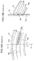
- a plurality of roller bits 74 to 76 supported in such a manner as to freely rotate around support axes O2 to O4 arranged in a periphery of an axis O1 of rotation of a cutter head 71 at a predetermined angle in a radial direction respectively are arranged on a front surface of the cutter head 71 of a shield excavator 61.
- axial portions 74a to 76a of the plurality of roller bits 74 to 76 are rotatably supported to the cutter head 71 through bearings 77 and 77, respectively.
- An existing pipe 72 in Fig. 9 is constituted by a concrete pipe wall 72a, a vertical reinforcement 72b and a horizontal reinforcement 72c.
- roller bit 76 of the horizontal blade type will be described below.
- four paths 76c on the surface of the existing pipe 72 to be crushed by the roller bit 76 of the horizontal blade type is coaxial with respect to the center O1 of rotation of the cutter head 71. Accordingly, there is little possibility that the roller bit 76 of the horizontal blade type cuts the vertical reinforcement 72b bent in a direction the same as a rotating direction S1 of the cutter head 71, and this is provided simply in order to crush the concrete pipe wall 72a.
- a plurality of paths 74c on the surface to be crushed of the existing pipe 72 by the roller bit 74 of the vertical blade type is substantially perpendicular to the vertical reinforcement 72b bent in the same direction as the rotating direction S1 of the cutter head 71. Accordingly, the roller bit 74 of the vertical blade type can cut the vertical reinforcement 72b at the pitch interval of the blade portion 74b thereof.
- roller bit 75 of the spiral blade type Since the roller bit 75 of the spiral blade type is structured such that a blade portion 75b is a spiral having a thread, paths 75c thereof (a two dot chain line) displaces an angle ⁇ 1 from paths (a single dot chain line) along the rotating direction S1 of the cutter head 71, respectively. Accordingly, a vertical reinforcement 72b bent to the same direction as the rotating direction S1 of the cutter head 71 is changed a direction to a position shown by a broken line at a slight angle ⁇ 2, however, is not cut away. In this case, the disc cutter of the spiral blade type is also disclosed in Japanese Unexamined Utility Model Publication No.
- spiral blades 54b and 55b each having a thread are projected from an outer peripheral surface of each of cutter main bodies 54a and 55a.
- These spiral blades 54b and 55b also serve the same function as that of the blade portion 75b of the roller bit 75 of the spiral blade type.
- the present invention is made in order to solve the problems in the above prior arts, and an object of the present invention is to provide a spiral-shaped roller cutter and a tunnel excavator cutter head provided with the same, which can efficiently and surely cut a reinforcement embedded in an existing pipe.
- a spiral-shaped roller cutter having a spiral-shaped blade portion on an outer peripheral surface, wherein the spiral-shaped blade portion is constituted by a plurality of threads.
- the spiral-shaped blade portion is constituted by a plurality of threads
- the spiral-shaped roller cutter having a great pitch angle and a narrow interval between the blades can be formed. Since the pitch of the blade is widened when increasing the pitch angle by the conventional spiral-shaped blade having a single thread, the interval between the blades is increased. Then, when setting to a plurality of threads, the interval between the blades can be set to be narrower than that of the single thread and in an optional manner even when the pitch angle is increased since it is produced by placing the other thread between one thread.
- a spiral-shaped roller cutter as recited in the first invention, wherein the spiral-shaped blade portion is formed in a taper shape in a facewidth direction of a tooth.
- a tooth groove gradually becomes wide toward a large diameter side from a small diameter side. Accordingly, the crushed concrete can be easily discharged without stopping the blade groove.
- a spiral-shaped roller cutter as recited in the first or second invention, wherein a pitch angle of the spiral-shaped blade portion having a plurality of threads is set to be 20 degrees to 80 degrees.
- the pitch angle can be determined to an optimum value in accordance with the object to be cut by changing the number of a plurality of threads.
- a tunnel excavator cutter head comprising a rotatable roller cutter mounted around an axis of rotation extending substantially to a radial direction of the cutter head, wherein the roller cutter is a spiral-shaped roller cutter provided with a spiral-shaped blade portion having a plurality of threads on an outer peripheral surface thereof.
- an angle (a pitch angle) formed between the axial direction of the reinforcement bent in the rotating direction of the cutter head and the spiral-shaped blade portion becomes great in an operation of crushing the concrete embedding the reinforcement by providing the spiral-shaped roller cutter having the spiral-shaped blade portion having a plurality of threads in the tunnel excavator cutter head, the reinforcement can be efficiently cut by a small pressing force due to a rolling operation of the spiral-shaped roller cutter. Further, since the interval between the blades is narrow, the reinforcement and the like can be finely crushed.
- the spiral-shaped roller cutter can easily catch the distal end portion of the reinforcement bent in the rotating direction of the cutter head by changing a number of the threads so as to select a magnitude of the pitch angle to an appropriate value in correspondence to the material to be cut, the reinforcement caught thereby can be easily cut due to a rolling operation of the spiral-shaped roller cutter, and the reinforcement can be shortened so that the length of the cut reinforcement becomes near the pitch length of the spiral-shaped blade portion.
- a tunnel excavator cutter head as recited in the first invention, wherein the spiral-shaped roller cutter is constituted by two kinds of spiral-shaped roller cutters in which pitch angles of the spiral-shaped blade portion having a plurality of threads are mutually directed to inverted directions.
- the paths of the respective blade portions of the two kinds of spiral-shaped roller cutters on the crushed surface of the concrete pipe cross to each other, so that even when the reinforcement exposing from the crushed surface of the concrete pipe is bent to a direction of the blade groove of one of the spiral-shaped roller cutters, it can be cut by the other of the spiral-shaped roller cutters.
- a tunnel excavator cutter head as recited in the first invention, wherein the spiral-shaped roller cutter is provided with the spiral-shaped roller cutter provided with the spiral-shaped blade portion having a plurality of threads, and any one of a disc-shaped roller cutter having a disc-shaped blade portion perpendicular to the axis of rotation and a spiral-shaped roller cutter having a thread of spiral-shaped blade portion.
- the reinforcement bent in the rotating direction of the cutter head by the spiral-shaped roller cutter having a plurality of threads can be efficiently cut by a small pressing force due to the rolling operation of the spiral-shaped roller cutter.
- the reinforcement can be efficiently cut by a small pressing force in the same manner as that of the spiral-shaped roller cutter having a plurality of threads due to the rolling operation of the disc-shaped roller cutter and the spiral-shaped roller cutter having a single thread.
- a tunnel excavator cutter head as recited in the third invention, wherein a cutting surface of the spiral-shaped roller cutter provided with the spiral-shaped blade portion having a plurality of threads and a cutting surface of any one of the disc-shaped roller cutter and the spiral-shaped roller cutter having a thread of spiral-shaped blade portion are disposed so as to be shifted at a predetermined amount in a direction of excavating a tunnel.
- the concrete portion can be crushed by the roller cutter suitable for each of the steps and subsequently the reinforcement is cut by the cutting surface of the other kind of roller cutter provided a predetermined amount at the back thereof.
- the roller cutters respectively suitable for crushing the concrete and cutting the reinforcement can be determined, a durability of each of the roller cutters can be improved.
- a tunnel excavator cutter head as recited in any one of the first, second, third and fourth inventions, wherein the cutter head is structured such as to rotate in a direction that an angle formed between a crush surface of a existing pipe and a hoop reinforcement within a non-crushed portion rotates from an acute angle to an obtuse angle when crushing the existing pipe in which the hoop reinforcement is embedded.
- the hoop reinforcement can be surely cut without being caught in the cutter head, a cutting efficiency of the hoop reinforcement can be improved. Further, since the hoop reinforcement is cut to a short piece, it can be efficiently conveyed in the same manner as normal excavated earth and sand without being caught in the cutter head or the screw conveyor.
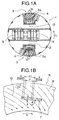
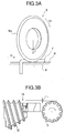
- a tunnel excavator cutter head in accordance with a first embodiment of the present invention will be in detail described below with reference to Figs. 1A to 3B.
- a tunnel excavator cutter head 1 has axes 2 and 2 respectively in a diametrical direction of the cutter head 1 and near an outer peripheral surface as shown in Fig. 1A, and spiral-shaped roller cutters 3 and 3 having a spiral-shaped blade portion 3a having a plurality of threads formed thereon are respectively mounted to the respective axes 2 and 2 of rotation so as to be freely rotated.
- Each of cutter bits 4 and 4 is fixed to an edge portion of a mounting hole of each of the spiral-shaped roller cutters 3 and 3 toward a rotational direction S1 of the cutter head 1.
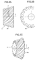
- the spiral-shaped roller cutter 3 is provided with the spiral-shaped blade portion 3a having a plurality of threads, as shown in Figs. 2A to 2C.
- the spiral-shaped blade portion 3a having a plurality of threads is formed in a taper shape and a pitch angle ⁇ thereof is, for example, 45 degrees.
- Each of normal disc cutters 5 and 5 are rotatably mounted in a diametrical direction perpendicular to the axes 2 and 2 of rotation of each of the spiral-shaped roller cutters 3 and 3.
- each of the spiral-shaped roller cutters 3 and 3 is pressed to a crushed surface of the existing pipe 6 and is rotated in a direction of an arrow S2.
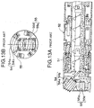
- Fig. 1B shows a part of the crushed surface of the existing pipe 6 as seen toward an excavating direction of the tunnel excavator, in which a lateral direction is inverted to the case of Fig. 1A.
- a front end portion of a reinforcement 7 embedded in the existing pipe 6 projects from the crushed surface of a concrete portion 8 in the existing pipe 6, however, is bent in the S1 direction corresponding to a rotating direction of the cutter head 1 by the cutter head 1.
- a pitch of the path 10 along an axial direction of the reinforcement is set to be p
- an angle (corresponding to a pitch angle) formed between a rotational tangent of the cutter head 1 and the path 10 of the spiral-shaped blade portion 3 is set to be ⁇ and a diameter of the reinforcement is set to be d
- the length ⁇ L of the reinforcement 7 becomes (d/tan ⁇ ) longer than the pitch p of the path 10 of the spiral-shaped blade portion 3a.
- a pitch angle ⁇ of the path 10 (which is equal to the pitch angle of the spiral-shaped blade portion 3a if no slip is present between the spiral-shaped blade portion 3a and the crushed surface of the existing pipe 6) is set to be great, it gets near the roller bit 74 of the vertical blade type in accordance with the prior art and an operation of rolling on the cut surface of the reinforcement 7 is reduced.
- the pitch angle ⁇ of the path 10 is set to be small, it gets near the roller bit 76 of the horizontal blade type in accordance with the prior art, and the path 10 gets near the tangential direction S1 of the rotation of the cutter head 1, so that it is hard to catch the reinforcement 7. Even if the reinforcement 7 can be caught, the cut reinforcement 7 is long since the angle formed between the axis of the reinforcement 7 and the cut surface is small, so that the reinforcement 7 is easily caught in the cutter head 1, the screw conveyor or the like.
- the distal end portion of the reinforcement 7 bent in the same direction as the rotating direction S1 of the cutter head 1 is pressed to the crushed surface of the concrete portion 8 due to a pressing force F by a blade portion 9a of the disc cutter 9 rotating in the S2 direction so as to be cut.
- the reinforcement 7 is significantly easily cut in comparison with the case that the disc cutter 9 is simply pressed to the distal end portion of the reinforcement 7. Accordingly, the distal end portion of the reinforcement 7 can be surely cut without entering into the concrete portion 8 by making the pressing force F small.
- the concrete portion 72a is first crushed by the disc-shaped roller cutter 12 since the disc-shaped roller cutter 12 is placed L1 forward from the spiral-shaped roller cutter 3, so that a plurality of vertical reinforcements 72b are exposed from the crushed surface thereof.
- the vertical reinforcements 72b are cut by the spiral-shaped roller cutter 3 after being bent in the rotational direction thereof by the cutter head 1.
- each of the roller cutters 3 and 12 can be efficiently used.
- the cutter head 1a in accordance with this embodiment is rotatably mounted by replacing one of two spiral-shaped roller cutters 3 and 3 shown in Fig. 1A by a spiral-shaped roller cutter 23 having an inverse pitch angle. Since the structure is the same as that of the first embodiment except this, the detailed description will be omitted.
- the other spiral-shaped roller cutter 3 is also pressed to the crushed surface, it is rotated in the S2 direction. Accordingly, since the path 10 becomes the same as the path 10 of the blade portion shown by the two dot chain line in Fig. 1B, the distal end portion of the reinforcement 7 projecting from the crushed surface of the crushed concrete portion 8 is finely cut by the spiral-shaped roller cutter 3 and the spiral-shaped roller cutter 23 after being bent in the rotational direction S2 of the cutter head 1a.
- the cutter head 1b in accordance with this embodiment is rotatably mounted to the cutter head 1b by replacing one of two spiral-shaped roller cutters 3 and 3 shown in Fig. 1A by a known disc-shaped roller cutter 12. Since the structure is the same as that of the first embodiment except this, the detailed description will be omitted.
- the disc-shaped roller cutter 12 When the cutter head 1b rotates in a direction of an arrow S1, the disc-shaped roller cutter 12 is rotated in a direction of an arrow S4 since it is pressed to a crushed surface. Accordingly, as shown by a two dot chain line in Fig. 5B, the concrete portion 8 is crushed by paths 11 of four blade portions of the disc-shaped roller cutter 12 rotated by a rotation of the cutter head 1b on the crushed surface. The distal end portion of the reinforcement 7 projecting from the crushed surface of the crushed concrete portion 8 is bent in the rotational direction S1 of the cutter head 1b.
- the other spiral-shaped roller cutter 3 is reduced in a load for crushing the concrete portion 8, so that a cutting performance of the reinforcement 7 and a durability of the spiral-shaped roller cutter 3 are widely improved.
- the crushing surface of the disc-shaped roller cutter 12 is placed so as to be a predetermined amount forward from the cutting surface of the spiral-shaped roller cutter, the concrete portion 8 can be surely crushed by the disc-shaped roller cutter 12, so that a load of the spiral-shaped roller cutter 3 is further reduced, whereby the performances mentioned above are further improved.
- the present invention is useful for a spiral-shaped roller cutter and a tunnel excavator cutter head provided with the same, which can efficiently and surely cut a reinforcement embedded in an existing pipe.
Landscapes
- Engineering & Computer Science (AREA)
- Mining & Mineral Resources (AREA)
- Life Sciences & Earth Sciences (AREA)
- Geology (AREA)
- Environmental & Geological Engineering (AREA)
- General Life Sciences & Earth Sciences (AREA)
- Geochemistry & Mineralogy (AREA)
- Physics & Mathematics (AREA)
- Fluid Mechanics (AREA)
- Mechanical Engineering (AREA)
- Excavating Of Shafts Or Tunnels (AREA)
Applications Claiming Priority (3)
| Application Number | Priority Date | Filing Date | Title |
|---|---|---|---|
| JP210580/96 | 1996-07-22 | ||
| JP21058096A JPH1037680A (ja) | 1996-07-22 | 1996-07-22 | 螺旋形刃部を有する螺旋形ローラカッタおよびトンネル掘進機のカッタヘッド |
| PCT/JP1997/002512 WO1998003772A1 (fr) | 1996-07-22 | 1997-07-22 | Organe cylindrique de coupe a spirales et tete de coupe pour foreuse de galerie le comportant |
Publications (2)
| Publication Number | Publication Date |
|---|---|
| EP0915231A1 true EP0915231A1 (fr) | 1999-05-12 |
| EP0915231A4 EP0915231A4 (fr) | 2000-11-15 |
Family
ID=16591674
Family Applications (1)
| Application Number | Title | Priority Date | Filing Date |
|---|---|---|---|
| EP97930849A Withdrawn EP0915231A4 (fr) | 1996-07-22 | 1997-07-22 | Organe cylindrique de coupe a spirales et tete de coupe pour foreuse de galerie le comportant |
Country Status (3)
| Country | Link |
|---|---|
| EP (1) | EP0915231A4 (fr) |
| JP (1) | JPH1037680A (fr) |
| WO (1) | WO1998003772A1 (fr) |
Cited By (1)
| Publication number | Priority date | Publication date | Assignee | Title |
|---|---|---|---|---|
| CN103510961A (zh) * | 2013-10-21 | 2014-01-15 | 华北电力大学 | 全断面隧道掘进机盘形滚刀刃宽和刃角的确定方法 |
Families Citing this family (2)
| Publication number | Priority date | Publication date | Assignee | Title |
|---|---|---|---|---|
| CN110030009B (zh) * | 2019-05-28 | 2024-06-25 | 中国铁建重工集团股份有限公司 | 一种用于长距离掘进的顶掘机及其施工方法 |
| CN113605909A (zh) * | 2021-07-30 | 2021-11-05 | 西南交通大学 | 一种新型tbm滚刀刀圈 |
Family Cites Families (4)
| Publication number | Priority date | Publication date | Assignee | Title |
|---|---|---|---|---|
| JPH0832192B2 (ja) | 1987-11-24 | 1996-03-27 | 株式会社安川電機 | 交流電動機の磁束検出装置 |
| JPH0325694U (fr) * | 1989-07-24 | 1991-03-15 | ||
| JP2911573B2 (ja) | 1990-09-14 | 1999-06-23 | 株式会社資生堂 | 洗浄剤組成物 |
| JP2584994Y2 (ja) * | 1991-04-16 | 1998-11-11 | 株式会社 錢高組 | 鉄筋コンクリート製埋設管の掘削破砕用カッターヘッド |
-
1996
- 1996-07-22 JP JP21058096A patent/JPH1037680A/ja active Pending
-
1997
- 1997-07-22 WO PCT/JP1997/002512 patent/WO1998003772A1/fr not_active Ceased
- 1997-07-22 EP EP97930849A patent/EP0915231A4/fr not_active Withdrawn
Non-Patent Citations (2)
| Title |
|---|
| No further relevant documents disclosed * |
| See also references of WO9803772A1 * |
Cited By (1)
| Publication number | Priority date | Publication date | Assignee | Title |
|---|---|---|---|---|
| CN103510961A (zh) * | 2013-10-21 | 2014-01-15 | 华北电力大学 | 全断面隧道掘进机盘形滚刀刃宽和刃角的确定方法 |
Also Published As
| Publication number | Publication date |
|---|---|
| EP0915231A4 (fr) | 2000-11-15 |
| JPH1037680A (ja) | 1998-02-10 |
| WO1998003772A1 (fr) | 1998-01-29 |
Similar Documents
| Publication | Publication Date | Title |
|---|---|---|
| JP3907757B2 (ja) | 回転衝撃螺旋ドリル | |
| CA2415116C (fr) | Appareil de broyage de souches | |
| JP4237285B2 (ja) | 穿孔工具 | |
| JPS6144730Y2 (fr) | ||
| JP4046851B2 (ja) | 削岩ドリル | |
| JPH04228796A (ja) | 削岩ドリル | |
| JP4676051B2 (ja) | ドリル工具 | |
| EP0915231A1 (fr) | Organe cylindrique de coupe a spirales et tete de coupe pour foreuse de galerie le comportant | |
| JPH07124809A (ja) | 切削屑排出孔を備えたコアドリル | |
| US4697653A (en) | Diamond setting in a cutting tooth in a drill bit with an increased effective diamond width | |
| JP3705295B1 (ja) | シールド機のカッタ及び分岐シールド用カッタ | |
| JP2013047444A (ja) | シールド掘進機とこれを用いた管路構築工法 | |
| JP3907756B2 (ja) | 回転衝撃螺旋ドリル | |
| US20040020693A1 (en) | Drill bit | |
| US4393949A (en) | Rock boring apparatus | |
| JP4706639B2 (ja) | 掘削工具 | |
| CN113445926B (zh) | 破岩钻头装置 | |
| AU2002212221A1 (en) | Drill bit | |
| JP2004044244A (ja) | 地中掘削機のローラカッタ、螺旋形ローラカッタおよびそれを装着したカッタヘッド | |
| JP3332842B2 (ja) | 掘削用のカッタリング及び掘削用のディスクカッタ | |
| JP5396443B2 (ja) | 鉄筋コンクリート管破砕用のローラカッタ及びカッタヘッド | |
| JPS6126470Y2 (fr) | ||
| JP2004019311A (ja) | ディスクビット、カッタヘッド及びカッタドラム | |
| JPH08333978A (ja) | カッタービット | |
| GB2426988A (en) | Tubular drill shoe |
Legal Events
| Date | Code | Title | Description |
|---|---|---|---|
| PUAI | Public reference made under article 153(3) epc to a published international application that has entered the european phase |
Free format text: ORIGINAL CODE: 0009012 |
|
| 17P | Request for examination filed |
Effective date: 19990106 |
|
| AK | Designated contracting states |
Kind code of ref document: A1 Designated state(s): DE FR GB |
|
| A4 | Supplementary search report drawn up and despatched |
Effective date: 20001005 |
|
| AK | Designated contracting states |
Kind code of ref document: A4 Designated state(s): DE FR GB |
|
| RIC1 | Information provided on ipc code assigned before grant |
Free format text: 7E 21D 9/08 A, 7E 21D 9/06 B, 7E 21B 10/10 B, 7E 21B 10/16 B, 7E 21D 9/10 B |
|
| 17Q | First examination report despatched |
Effective date: 20020919 |
|
| STAA | Information on the status of an ep patent application or granted ep patent |
Free format text: STATUS: THE APPLICATION IS DEEMED TO BE WITHDRAWN |
|
| 18D | Application deemed to be withdrawn |
Effective date: 20031223 |