EP0915288A2 - Chaudière de récupération - Google Patents
Chaudière de récupération Download PDFInfo
- Publication number
- EP0915288A2 EP0915288A2 EP98119074A EP98119074A EP0915288A2 EP 0915288 A2 EP0915288 A2 EP 0915288A2 EP 98119074 A EP98119074 A EP 98119074A EP 98119074 A EP98119074 A EP 98119074A EP 0915288 A2 EP0915288 A2 EP 0915288A2
- Authority
- EP
- European Patent Office
- Prior art keywords
- ammonia injection
- exhaust gas
- evaporator
- heat recovery
- boiler
- Prior art date
- Legal status (The legal status is an assumption and is not a legal conclusion. Google has not performed a legal analysis and makes no representation as to the accuracy of the status listed.)
- Granted
Links
- 238000011084 recovery Methods 0.000 title claims abstract description 75
- QGZKDVFQNNGYKY-UHFFFAOYSA-N Ammonia Chemical compound N QGZKDVFQNNGYKY-UHFFFAOYSA-N 0.000 claims abstract description 434
- 229910021529 ammonia Inorganic materials 0.000 claims abstract description 217
- 238000002347 injection Methods 0.000 claims abstract description 184
- 239000007924 injection Substances 0.000 claims abstract description 184
- 239000007789 gas Substances 0.000 claims abstract description 140
- MWUXSHHQAYIFBG-UHFFFAOYSA-N Nitric oxide Chemical compound O=[N] MWUXSHHQAYIFBG-UHFFFAOYSA-N 0.000 claims abstract description 111
- 238000011144 upstream manufacturing Methods 0.000 claims abstract description 36
- 238000009434 installation Methods 0.000 claims abstract description 11
- 238000010248 power generation Methods 0.000 description 11
- 239000003054 catalyst Substances 0.000 description 9
- 238000010276 construction Methods 0.000 description 7
- 230000007613 environmental effect Effects 0.000 description 3
- 238000006722 reduction reaction Methods 0.000 description 2
- 238000002485 combustion reaction Methods 0.000 description 1
- 238000001816 cooling Methods 0.000 description 1
- 230000007547 defect Effects 0.000 description 1
- 230000009977 dual effect Effects 0.000 description 1
- 230000000694 effects Effects 0.000 description 1
- 238000004134 energy conservation Methods 0.000 description 1
- 238000000034 method Methods 0.000 description 1
- 238000012986 modification Methods 0.000 description 1
- 230000004048 modification Effects 0.000 description 1
- 230000000630 rising effect Effects 0.000 description 1
- 239000006200 vaporizer Substances 0.000 description 1
- XLYOFNOQVPJJNP-UHFFFAOYSA-N water Substances O XLYOFNOQVPJJNP-UHFFFAOYSA-N 0.000 description 1
Images






Classifications
-
- F—MECHANICAL ENGINEERING; LIGHTING; HEATING; WEAPONS; BLASTING
- F22—STEAM GENERATION
- F22B—METHODS OF STEAM GENERATION; STEAM BOILERS
- F22B1/00—Methods of steam generation characterised by form of heating method
- F22B1/02—Methods of steam generation characterised by form of heating method by exploitation of the heat content of hot heat carriers
- F22B1/18—Methods of steam generation characterised by form of heating method by exploitation of the heat content of hot heat carriers the heat carrier being a hot gas, e.g. waste gas such as exhaust gas of internal-combustion engines
- F22B1/1807—Methods of steam generation characterised by form of heating method by exploitation of the heat content of hot heat carriers the heat carrier being a hot gas, e.g. waste gas such as exhaust gas of internal-combustion engines using the exhaust gases of combustion engines
- F22B1/1815—Methods of steam generation characterised by form of heating method by exploitation of the heat content of hot heat carriers the heat carrier being a hot gas, e.g. waste gas such as exhaust gas of internal-combustion engines using the exhaust gases of combustion engines using the exhaust gases of gas-turbines
-
- F—MECHANICAL ENGINEERING; LIGHTING; HEATING; WEAPONS; BLASTING
- F22—STEAM GENERATION
- F22B—METHODS OF STEAM GENERATION; STEAM BOILERS
- F22B37/00—Component parts or details of steam boilers
- F22B37/008—Adaptations for flue-gas purification in steam generators
-
- Y—GENERAL TAGGING OF NEW TECHNOLOGICAL DEVELOPMENTS; GENERAL TAGGING OF CROSS-SECTIONAL TECHNOLOGIES SPANNING OVER SEVERAL SECTIONS OF THE IPC; TECHNICAL SUBJECTS COVERED BY FORMER USPC CROSS-REFERENCE ART COLLECTIONS [XRACs] AND DIGESTS
- Y02—TECHNOLOGIES OR APPLICATIONS FOR MITIGATION OR ADAPTATION AGAINST CLIMATE CHANGE
- Y02C—CAPTURE, STORAGE, SEQUESTRATION OR DISPOSAL OF GREENHOUSE GASES [GHG]
- Y02C20/00—Capture or disposal of greenhouse gases
- Y02C20/10—Capture or disposal of greenhouse gases of nitrous oxide (N2O)
Definitions
- the ammonia injection section 1 of the exhaust heat recovery boiler is arranged on an upstream side of the high pressure evaporator 4 with respect to the exhaust gas flow direction. Further, ammonia needs to be uniformly mixed with the exhaust gas, and for this reason, the ammonia injection section 1 is arranged at a position separated from the denitration reactor 5 to some degree in a manner that the high pressure evaporator 4 is interposed between the injection section 1 and the denitration reactor 5. When passing through the high pressure evaporator 4 having many heat transfer pipes regularly arranged, the ammonia and the exhaust gas are uniformly mixed. The ammonia is oxidized at a temperature of 490 °C or more, and then, a nitrogen oxide is generated.
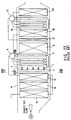
- the ammonia injection section 1 is arranged on a downstream side of the high pressure primary superheater 13 from the exhaust gas flow direction and on the upstream side of the high pressure evaporator 4, and a planned gas temperature is about 470 °C . In this manner, in the exhaust heat recovery boiler, a harmful nitrogen oxide contained in the exhaust gas is removed while heat exchange being made by the heat transfer pipes.
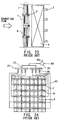
- Fig. 24 is a view showing the ammonia injection section of Fig. 22 in the case of viewing from the exhaust gas flow direction.
- ammonia injection nozzles 8 are vertically alternately provided on the ammonia injection pipe 7 so that the ammonia is uniformly mixed with the exhaust gas. Further, the flow rate of ammonia is controlled by means of ammonia flow control valves 26 so that the ammonia is uniformly mixed with the exhaust gas. As described above, the ammonia injection section is constructed in a manner that ammonia is uniformly injected to the overall section of exhaust gas passage in the boiler duct.
- an exhaust heat recovery boiler in which an exhaust gas discharged from, for example, gas turbine, into a boiler duct to recover a heat of the exhaust gas and ammonia is injected to and mixed with the exhaust gas so as to reduce nitrogen oxide contained in the exhaust gas, the exhaust heat recovery boiler comprising:
- an exhaust heat recovery boiler in which an exhaust gas discharged from, for example, a gas turbine, into a boiler duct to recover a heat of the exhaust gas and ammonia is injected to and mixed with the exhaust gas so as to reduce nitrogen oxide contained in the exhaust gas, the exhaust heat recovery boiler comprising:
- the ammonia injection unit is disposed on the upstream side or downstream side of the downcomer pipe unit.
- the ammonia injection unit includes a plurality of ammonia injection pipes, a plurality of ammonia injection pipe supporting members and a number of ammonia injection nozzles
- the downcomer pipe unit includes a plurality of downcomer pipes, the ammonia injection pipe supporting members being disposed in parallel to the downcomer pipes with respect to the exhaust gas flow.
- the ammonia injection nozzles are formed to two ammonia injection pipes, which are arranged in the same level with respect to the exhaust gas flow, the injection nozzles being formed in a manner that injection nozzles formed to one ammonia injection pipe and injection nozzles formed to another one ammonia injection pipe are arranged alternately with respect to the exhaust gas flow direction.
- the evaporator may be divided, and the ammonia injection unit and the boiler downcomer pipe unit are interposed between the divided evaporators.
- the evaporator may be divided, and the ammonia injection unit and the boiler downcomer pipe unit are interposed between the divided evaporators.
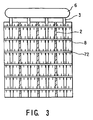
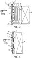
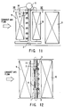
- Figs. 1 to 3 are views showing an ammonia injection section according to a first embodiment of the present invention.
- the ammonia injection section 1 is arranged on an upstream side of a high pressure evaporator 4 with respect to the exhaust gas flow direction in the boiler duct 14 and at the same position as a high pressure drum downcomer pipe 3 of a high pressure drum 6.
- the exhaust gas flows from the ammonia injection section 1 into the denitration reactor 5 via the high pressure evaporator 4, which is composed of a plurality of heat transfer pipes arranged in parallel to each other, so that a nitrogen oxide can be removed in a state that ammonia and exhaust gas are uniformly mixed with each other.
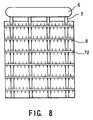
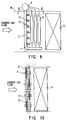
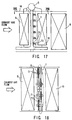
- Figs. 4 and 5 are views showing an ammonia injection section according to a modified embodiment of the first embodiment of the present invention.
- the ammonia injection section 1 and the high pressure drum downcomer pipe 3 are arranged at the same position when viewing the side of the exhaust heat recovery boiler.
- the exhaust gas flows from the ammonia injection section 1 into the denitration reactor 5 via the high pressure evaporator 4, so that a nitrogen oxide can be removed in a state that ammonia and exhaust gas are uniformly mixed with each other.
- the mixed gas smoothly flows into the denitration removal reactor 5 because no high pressure drum downcomer pipe 3 is provided on a pipe group outlet of the high pressure evaporator 4, and therefore, catalyst is effectively activated, so that the NOx removal efficiency can be improved even the same quantity of catalyst as compared with the conventional case.
- the ammonia injection section 1 and the high pressure drum downcomer pipe 3 are arranged at the same position when viewing the side of the exhaust heat recovery boiler.
- the exhaust gas flows from the ammonia injection section 1 into the denitration reactor 5 via the high pressure evaporator 4, so that a nitrogen oxide can be removed in a state that ammonia and exhaust gas are uniformly mixed with each other.
- the mixed gas smoothly flows into the denitration reactor 5 because no high pressure drum downcomer pipe 3 is provided on a pipe group outlet of the high pressure evaporator 4, and therefore, catalyst is effectively activated, so that the NOx removal efficiency can be improved even with the same quantity of catalyst as compared with the conventional case.
- the ammonia injection section 1 and the high pressure drum downcomer pipe 3 are arranged at the same position when view the side of the exhaust heat recovery boiler, like the first and second embodiments. Further, the high pressure drum downcomer pipe 3 and the ammonia injection section support member 2 are arranged in parallel in the horizontal direction, like the first embodiment.
- the exhaust gas passes through the first high pressure evaporator section 9, and then, is mixed with ammonia in the ammonia injection section 1. Further, the exhaust gas passes through the second high pressure evaporator section 10, and thereafter, a nitrogen oxide is removed by means of the denitration reactor 5. Therefore, according to this third embodiment, it is possible to improve the NOx removal efficiency as compared with the conventional case.
- this embodiment differs from the third embodiment in that the ammonia injection pipes 71 and 72 and the ammonia injection nozzles 8 are arranged on a down stream side of the high pressure drum downcomer pipe 3 with respect to the exhaust gas flow direction in the boiler duct 14, and other construction is the same as that of the first embodiment.
- like reference numerals are used to designate the same components as those of the first embodiment, and the overlapping explanation is omitted.
- the exhaust gas passes more heat transfer pipe groups than the conventional one before it reaches the ammonia injection section 1 so that the exhaust gas reaches the ammonia injection section 1 after the heat exchanges are performed many times.
- this fourth embodiment differs from the third embodiment in that the high pressure drum downcomer pipe 3 also functions as the ammonia injection section support member 2 in order to eliminate the ammonia injection section support member, and other construction is the same as that of the first embodiment.
- like reference numerals are used to designate the same components as those of the first embodiment, and the overlapping explanation is omitted.
- Fig. 21 is a view showing an ammonia injection section according to a sixth embodiment of the present invention.
- the ammonia injection section 1 is constructed with the use of upper and lower pipe headers 11 and 12. Therefore, a space in the exhaust gas flow direction is saved, and it is possible to perform ammonia injection at a proper exhaust gas temperature.
Landscapes
- Engineering & Computer Science (AREA)
- Combustion & Propulsion (AREA)
- Thermal Sciences (AREA)
- Mechanical Engineering (AREA)
- General Engineering & Computer Science (AREA)
- Chemical & Material Sciences (AREA)
- Physics & Mathematics (AREA)
- Life Sciences & Earth Sciences (AREA)
- Sustainable Development (AREA)
- Sustainable Energy (AREA)
- Chimneys And Flues (AREA)
- Treating Waste Gases (AREA)
- Exhaust Gas Treatment By Means Of Catalyst (AREA)
Applications Claiming Priority (3)
| Application Number | Priority Date | Filing Date | Title |
|---|---|---|---|
| JP27620397A JP3373771B2 (ja) | 1997-10-08 | 1997-10-08 | 排熱回収ボイラ |
| JP276203/97 | 1997-10-08 | ||
| JP27620397 | 1997-10-08 |
Publications (3)
| Publication Number | Publication Date |
|---|---|
| EP0915288A2 true EP0915288A2 (fr) | 1999-05-12 |
| EP0915288A3 EP0915288A3 (fr) | 2000-02-23 |
| EP0915288B1 EP0915288B1 (fr) | 2004-02-25 |
Family
ID=17566130
Family Applications (1)
| Application Number | Title | Priority Date | Filing Date |
|---|---|---|---|
| EP98119074A Expired - Lifetime EP0915288B1 (fr) | 1997-10-08 | 1998-10-08 | Chaudière de récupération |
Country Status (8)
| Country | Link |
|---|---|
| US (4) | US6050226A (fr) |
| EP (1) | EP0915288B1 (fr) |
| JP (1) | JP3373771B2 (fr) |
| KR (1) | KR100309959B1 (fr) |
| CN (1) | CN1158470C (fr) |
| AT (1) | ATE260440T1 (fr) |
| CA (1) | CA2249805C (fr) |
| TW (1) | TW421701B (fr) |
Cited By (3)
| Publication number | Priority date | Publication date | Assignee | Title |
|---|---|---|---|---|
| EP2587011A1 (fr) * | 2011-10-26 | 2013-05-01 | General Electric Company | Systèmes d'injection d'ammoniac |
| CN105258092A (zh) * | 2015-11-13 | 2016-01-20 | 江苏绿叶锅炉有限公司 | 燃气强制循环余热锅炉 |
| EP2702324B1 (fr) * | 2011-04-25 | 2016-09-14 | Nooter/Eriksen, Inc. | Générateur de vapeur à récupération de chaleur et évaporateur comprenant plusieurs collecteurs |
Families Citing this family (25)
| Publication number | Priority date | Publication date | Assignee | Title |
|---|---|---|---|---|
| JP3373771B2 (ja) * | 1997-10-08 | 2003-02-04 | 株式会社東芝 | 排熱回収ボイラ |
| DE19959342A1 (de) * | 1999-12-09 | 2001-06-13 | Abb Alstom Power Ch Ag | Abhitzedampferzeuger |
| US6851514B2 (en) * | 2002-04-15 | 2005-02-08 | Air Handling Engineering Ltd. | Outlet silencer and heat recovery structures for gas turbine |
| US6895740B2 (en) * | 2003-01-21 | 2005-05-24 | Donald C. Erickson | Steam ammonia power cycle |
| US7331312B2 (en) * | 2005-10-31 | 2008-02-19 | Boiler Clinic, Inc. | Waste heat recovery apparatus and method for boiler system |
| US20080134994A1 (en) * | 2005-10-31 | 2008-06-12 | Sungkyou Choi | Waste Heat Recovery Apparatus and Method for Boiler System |
| US7578265B2 (en) * | 2006-05-09 | 2009-08-25 | Babcock & Wilcox Power Generation Group, Inc. | Multiple pass economizer and method for SCR temperature control |
| US8017084B1 (en) * | 2008-06-11 | 2011-09-13 | Callidus Technologies, L.L.C. | Ammonia injection grid for a selective catalytic reduction system |
| US20100175366A1 (en) * | 2009-01-09 | 2010-07-15 | General Electric Company | Ammonia injection system for peaker cycle |
| US20100319348A1 (en) * | 2009-05-26 | 2010-12-23 | Worleyparsons Group, Inc. | Waste heat recovery system |
| US8516786B2 (en) * | 2009-08-13 | 2013-08-27 | General Electric Company | System and method for injection of cooling air into exhaust gas flow |
| CN102650218B (zh) * | 2011-10-24 | 2014-09-03 | 章礼道 | 配有蒸发式氢气冷却系统的汽轮发电机 |
| US8734745B2 (en) * | 2012-08-10 | 2014-05-27 | Nooter/Eriksen, Inc. | Ammonia injection system for an HRSG |
| TWI504844B (zh) * | 2012-11-30 | 2015-10-21 | Ron Hsin Chang | 一種揮發性有機化學廢氣處理並回收能源的方法及使用該方法的蓄熱再生氧化型廢熱回收鍋爐 |
| US10274553B2 (en) * | 2013-03-15 | 2019-04-30 | Canon U.S.A., Inc. | Needle placement manipulator with attachment for RF-coil |
| CN103277788A (zh) * | 2013-05-30 | 2013-09-04 | 万平 | 锅炉的scr调温系统和调节锅炉scr入口烟温的方法 |
| CN104101112B (zh) * | 2014-07-11 | 2015-11-18 | 上海锅炉厂有限公司 | 一种太阳能集热接收器 |
| JP2017032232A (ja) * | 2015-08-04 | 2017-02-09 | パナソニック株式会社 | 蒸発器及びランキンサイクルシステム |
| US10137421B2 (en) | 2015-11-12 | 2018-11-27 | Doosan Heavy Industries Construction Co., Ltd. | Static mixer |
| CN106871148B (zh) * | 2017-03-31 | 2023-04-25 | 冯力燕 | 锅炉脱硝的三通投切装置 |
| FI128387B (fi) * | 2018-05-11 | 2020-04-15 | Varo Teollisuuspalvelut Oy | Soodakattilavuodon toteaminen |
| JP6665242B2 (ja) * | 2018-08-06 | 2020-03-13 | 三菱日立パワーシステムズ株式会社 | 排熱回収ボイラ |
| CN109289519A (zh) * | 2018-10-29 | 2019-02-01 | 海南中航特玻材料有限公司 | 一种烟气脱硝净化工艺 |
| CN111174189A (zh) * | 2019-08-26 | 2020-05-19 | 浙江卫星能源有限公司 | 一种用于燃气轮机尾气高效余热回收及脱硝联用的工艺 |
| CN112781025A (zh) * | 2020-12-29 | 2021-05-11 | 哈尔滨锅炉厂有限责任公司 | 一种用于余热锅炉的直流汽水系统及其使用方法 |
Family Cites Families (9)
| Publication number | Priority date | Publication date | Assignee | Title |
|---|---|---|---|---|
| US4160805A (en) * | 1977-07-14 | 1979-07-10 | Hitachi Shipbuilding & Engineering Co. Ltd. | Boiler containing denitrator |
| JPS6017967B2 (ja) * | 1978-01-18 | 1985-05-08 | 株式会社日立製作所 | 排熱回収ボイラ装置 |
| JPS6155501A (ja) * | 1984-08-24 | 1986-03-20 | 株式会社日立製作所 | 排熱回収ボイラ |
| JPH0681891B2 (ja) * | 1985-04-13 | 1994-10-19 | バブコツク日立株式会社 | コンバインドサイクルプラントの起動方法 |
| JP2554101B2 (ja) * | 1987-09-28 | 1996-11-13 | 三菱重工業株式会社 | 排ガスボイラ |
| DE59300573D1 (de) * | 1992-03-16 | 1995-10-19 | Siemens Ag | Verfahren zum Betreiben einer Anlage zur Dampferzeugung und Dampferzeugeranlage. |
| JP3727668B2 (ja) * | 1993-09-17 | 2005-12-14 | 三菱重工業株式会社 | 排ガスボイラ |
| JPH1057767A (ja) * | 1996-08-22 | 1998-03-03 | Hitachi Zosen Corp | 排ガス脱硝システムにおけるアンモニア注入装置 |
| JP3373771B2 (ja) * | 1997-10-08 | 2003-02-04 | 株式会社東芝 | 排熱回収ボイラ |
-
1997
- 1997-10-08 JP JP27620397A patent/JP3373771B2/ja not_active Expired - Fee Related
-
1998
- 1998-10-07 US US09/167,714 patent/US6050226A/en not_active Expired - Lifetime
- 1998-10-07 TW TW087116613A patent/TW421701B/zh not_active IP Right Cessation
- 1998-10-08 EP EP98119074A patent/EP0915288B1/fr not_active Expired - Lifetime
- 1998-10-08 CN CNB981245374A patent/CN1158470C/zh not_active Expired - Fee Related
- 1998-10-08 AT AT98119074T patent/ATE260440T1/de not_active IP Right Cessation
- 1998-10-08 CA CA002249805A patent/CA2249805C/fr not_active Expired - Fee Related
- 1998-10-08 KR KR1019980042062A patent/KR100309959B1/ko not_active Expired - Fee Related
-
2000
- 2000-02-07 US US09/499,451 patent/US6289850B1/en not_active Expired - Lifetime
- 2000-12-04 US US09/727,581 patent/US6334410B2/en not_active Expired - Lifetime
-
2001
- 2001-06-28 US US09/892,881 patent/US6435138B2/en not_active Expired - Lifetime
Cited By (4)
| Publication number | Priority date | Publication date | Assignee | Title |
|---|---|---|---|---|
| EP2702324B1 (fr) * | 2011-04-25 | 2016-09-14 | Nooter/Eriksen, Inc. | Générateur de vapeur à récupération de chaleur et évaporateur comprenant plusieurs collecteurs |
| EP2587011A1 (fr) * | 2011-10-26 | 2013-05-01 | General Electric Company | Systèmes d'injection d'ammoniac |
| CN105258092A (zh) * | 2015-11-13 | 2016-01-20 | 江苏绿叶锅炉有限公司 | 燃气强制循环余热锅炉 |
| CN105258092B (zh) * | 2015-11-13 | 2016-11-30 | 江苏绿叶锅炉有限公司 | 燃气强制循环余热锅炉 |
Also Published As
| Publication number | Publication date |
|---|---|
| US6289850B1 (en) | 2001-09-18 |
| KR19990036949A (ko) | 1999-05-25 |
| US20010035136A1 (en) | 2001-11-01 |
| CN1215818A (zh) | 1999-05-05 |
| JP3373771B2 (ja) | 2003-02-04 |
| US6334410B2 (en) | 2002-01-01 |
| CN1158470C (zh) | 2004-07-21 |
| CA2249805C (fr) | 2002-12-10 |
| CA2249805A1 (fr) | 1999-04-08 |
| US6435138B2 (en) | 2002-08-20 |
| EP0915288A3 (fr) | 2000-02-23 |
| ATE260440T1 (de) | 2004-03-15 |
| JPH11108334A (ja) | 1999-04-23 |
| KR100309959B1 (ko) | 2001-12-17 |
| TW421701B (en) | 2001-02-11 |
| EP0915288B1 (fr) | 2004-02-25 |
| US20010000094A1 (en) | 2001-04-05 |
| US6050226A (en) | 2000-04-18 |
Similar Documents
| Publication | Publication Date | Title |
|---|---|---|
| CA2249805C (fr) | Chaudiere de recuperation de la chaleur de gaz d'echappement | |
| AU2009204331B2 (en) | Flexible assembly of recuperator for combustion turbine exhaust | |
| US7021248B2 (en) | Passive system for optimal NOx reduction via selective catalytic reduction with variable boiler load | |
| US6125634A (en) | Power plant | |
| EP3077632B1 (fr) | Système à cycle combiné | |
| US4944252A (en) | Reheat type exhaust gas boiler | |
| CN100404799C (zh) | 蒸汽轮机设备 | |
| JP4348032B2 (ja) | 排熱回収ボイラ | |
| JP2753169B2 (ja) | 複圧式排熱回収ボイラ | |
| JP2001272001A (ja) | ボイラ装置 | |
| JP2024080906A (ja) | 排ガスバイパス装置及び排熱回収ボイラ並びに排ガスバイパス方法 | |
| JP3737186B2 (ja) | 排熱回収装置 | |
| CN223036415U (zh) | 一种卧式垃圾焚烧余热锅炉省煤器双流程布置结构 | |
| MXPA98008279A (en) | Salt heat recovery boiler | |
| JPH03117801A (ja) | 排熱回収ボイラ | |
| JP3227137B2 (ja) | 排熱回収ボイラ | |
| KR200167978Y1 (ko) | 복합형 폐열회수 증기발생기 | |
| JP2892141B2 (ja) | 複圧式排熱回収ボイラ | |
| JPS59153095A (ja) | 熱交換装置 | |
| JPH11350921A (ja) | 排熱回収ボイラ | |
| JPS59150201A (ja) | 熱交換装置 | |
| JPH05118508A (ja) | 伝熱管支持装置 | |
| KR200173321Y1 (ko) | 병렬배치의 열교환기 | |
| JP2004101045A (ja) | 竪型排熱回収ボイラ | |
| JPH11257602A (ja) | ボイラ |
Legal Events
| Date | Code | Title | Description |
|---|---|---|---|
| PUAI | Public reference made under article 153(3) epc to a published international application that has entered the european phase |
Free format text: ORIGINAL CODE: 0009012 |
|
| 17P | Request for examination filed |
Effective date: 19981008 |
|
| AK | Designated contracting states |
Kind code of ref document: A2 Designated state(s): AT NL |
|
| AX | Request for extension of the european patent |
Free format text: AL;LT;LV;MK;RO;SI |
|
| PUAL | Search report despatched |
Free format text: ORIGINAL CODE: 0009013 |
|
| AK | Designated contracting states |
Kind code of ref document: A3 Designated state(s): AT BE CH CY DE DK ES FI FR GB GR IE IT LI LU MC NL PT SE |
|
| AX | Request for extension of the european patent |
Free format text: AL;LT;LV;MK;RO;SI |
|
| AKX | Designation fees paid |
Free format text: AT NL |
|
| 17Q | First examination report despatched |
Effective date: 20020315 |
|
| REG | Reference to a national code |
Ref country code: DE Ref legal event code: 8566 |
|
| GRAP | Despatch of communication of intention to grant a patent |
Free format text: ORIGINAL CODE: EPIDOSNIGR1 |
|
| GRAS | Grant fee paid |
Free format text: ORIGINAL CODE: EPIDOSNIGR3 |
|
| GRAA | (expected) grant |
Free format text: ORIGINAL CODE: 0009210 |
|
| AK | Designated contracting states |
Kind code of ref document: B1 Designated state(s): AT NL |
|
| PLBE | No opposition filed within time limit |
Free format text: ORIGINAL CODE: 0009261 |
|
| STAA | Information on the status of an ep patent application or granted ep patent |
Free format text: STATUS: NO OPPOSITION FILED WITHIN TIME LIMIT |
|
| 26N | No opposition filed |
Effective date: 20041126 |
|
| PGFP | Annual fee paid to national office [announced via postgrant information from national office to epo] |
Ref country code: AT Payment date: 20091013 Year of fee payment: 12 |
|
| PG25 | Lapsed in a contracting state [announced via postgrant information from national office to epo] |
Ref country code: AT Free format text: LAPSE BECAUSE OF NON-PAYMENT OF DUE FEES Effective date: 20101008 |
|
| PGFP | Annual fee paid to national office [announced via postgrant information from national office to epo] |
Ref country code: NL Payment date: 20131010 Year of fee payment: 16 |
|
| REG | Reference to a national code |
Ref country code: NL Ref legal event code: V1 Effective date: 20150501 |
|
| PG25 | Lapsed in a contracting state [announced via postgrant information from national office to epo] |
Ref country code: NL Free format text: LAPSE BECAUSE OF NON-PAYMENT OF DUE FEES Effective date: 20150501 |