EP0915678B1 - Chirurgische implantate und deren anbringungssysteme - Google Patents
Chirurgische implantate und deren anbringungssysteme Download PDFInfo
- Publication number
- EP0915678B1 EP0915678B1 EP97931921A EP97931921A EP0915678B1 EP 0915678 B1 EP0915678 B1 EP 0915678B1 EP 97931921 A EP97931921 A EP 97931921A EP 97931921 A EP97931921 A EP 97931921A EP 0915678 B1 EP0915678 B1 EP 0915678B1
- Authority
- EP
- European Patent Office
- Prior art keywords
- stent
- wire
- occluding
- turns
- connector
- Prior art date
- Legal status (The legal status is an assumption and is not a legal conclusion. Google has not performed a legal analysis and makes no representation as to the accuracy of the status listed.)
- Expired - Lifetime
Links
- 239000007943 implant Substances 0.000 title description 12
- 239000000463 material Substances 0.000 claims abstract description 20
- 230000003446 memory effect Effects 0.000 claims abstract description 8
- 238000000576 coating method Methods 0.000 claims description 13
- 238000000034 method Methods 0.000 claims description 12
- 239000011248 coating agent Substances 0.000 claims description 6
- 238000002513 implantation Methods 0.000 claims description 4
- 238000004804 winding Methods 0.000 claims description 4
- 230000000144 pharmacologic effect Effects 0.000 claims description 3
- 230000023555 blood coagulation Effects 0.000 claims description 2
- 210000000746 body region Anatomy 0.000 claims description 2
- 230000021164 cell adhesion Effects 0.000 claims description 2
- 108090000623 proteins and genes Proteins 0.000 claims description 2
- 102000004169 proteins and genes Human genes 0.000 claims description 2
- 230000000717 retained effect Effects 0.000 claims description 2
- 238000000926 separation method Methods 0.000 claims description 2
- 239000012781 shape memory material Substances 0.000 claims description 2
- 210000003017 ductus arteriosus Anatomy 0.000 abstract description 7
- 229910001285 shape-memory alloy Inorganic materials 0.000 description 9
- 239000008280 blood Substances 0.000 description 7
- 210000004369 blood Anatomy 0.000 description 7
- 238000013461 design Methods 0.000 description 6
- 208000027418 Wounds and injury Diseases 0.000 description 5
- 238000010438 heat treatment Methods 0.000 description 5
- 229910052751 metal Inorganic materials 0.000 description 5
- 239000002184 metal Substances 0.000 description 5
- 210000004204 blood vessel Anatomy 0.000 description 4
- 239000003795 chemical substances by application Substances 0.000 description 4
- 230000000694 effects Effects 0.000 description 4
- 229920003023 plastic Polymers 0.000 description 4
- 239000004033 plastic Substances 0.000 description 4
- 239000000956 alloy Substances 0.000 description 3
- 210000000709 aorta Anatomy 0.000 description 3
- 238000004519 manufacturing process Methods 0.000 description 3
- 229910000734 martensite Inorganic materials 0.000 description 3
- 150000002739 metals Chemical class 0.000 description 3
- 230000005012 migration Effects 0.000 description 3
- 238000013508 migration Methods 0.000 description 3
- 210000001147 pulmonary artery Anatomy 0.000 description 3
- 239000010935 stainless steel Substances 0.000 description 3
- 229910001220 stainless steel Inorganic materials 0.000 description 3
- 238000001356 surgical procedure Methods 0.000 description 3
- 230000002792 vascular Effects 0.000 description 3
- PXHVJJICTQNCMI-UHFFFAOYSA-N Nickel Chemical compound [Ni] PXHVJJICTQNCMI-UHFFFAOYSA-N 0.000 description 2
- 208000007536 Thrombosis Diseases 0.000 description 2
- 238000005299 abrasion Methods 0.000 description 2
- 230000009471 action Effects 0.000 description 2
- 229910045601 alloy Inorganic materials 0.000 description 2
- 230000017531 blood circulation Effects 0.000 description 2
- 230000004663 cell proliferation Effects 0.000 description 2
- 239000000470 constituent Substances 0.000 description 2
- 238000010276 construction Methods 0.000 description 2
- 239000000110 cooling liquid Substances 0.000 description 2
- 230000006870 function Effects 0.000 description 2
- 239000007788 liquid Substances 0.000 description 2
- 239000002831 pharmacologic agent Substances 0.000 description 2
- 229920000747 poly(lactic acid) Polymers 0.000 description 2
- 239000004626 polylactic acid Substances 0.000 description 2
- 230000008569 process Effects 0.000 description 2
- 238000011282 treatment Methods 0.000 description 2
- 206010000060 Abdominal distension Diseases 0.000 description 1
- 201000001320 Atherosclerosis Diseases 0.000 description 1
- BHPQYMZQTOCNFJ-UHFFFAOYSA-N Calcium cation Chemical compound [Ca+2] BHPQYMZQTOCNFJ-UHFFFAOYSA-N 0.000 description 1
- OKTJSMMVPCPJKN-UHFFFAOYSA-N Carbon Chemical compound [C] OKTJSMMVPCPJKN-UHFFFAOYSA-N 0.000 description 1
- 206010053567 Coagulopathies Diseases 0.000 description 1
- 102000008186 Collagen Human genes 0.000 description 1
- 108010035532 Collagen Proteins 0.000 description 1
- 208000032170 Congenital Abnormalities Diseases 0.000 description 1
- 206010010356 Congenital anomaly Diseases 0.000 description 1
- 208000005189 Embolism Diseases 0.000 description 1
- DGAQECJNVWCQMB-PUAWFVPOSA-M Ilexoside XXIX Chemical compound C[C@@H]1CC[C@@]2(CC[C@@]3(C(=CC[C@H]4[C@]3(CC[C@@H]5[C@@]4(CC[C@@H](C5(C)C)OS(=O)(=O)[O-])C)C)[C@@H]2[C@]1(C)O)C)C(=O)O[C@H]6[C@@H]([C@H]([C@@H]([C@H](O6)CO)O)O)O.[Na+] DGAQECJNVWCQMB-PUAWFVPOSA-M 0.000 description 1
- 229910000990 Ni alloy Inorganic materials 0.000 description 1
- 229920000954 Polyglycolide Polymers 0.000 description 1
- ZLMJMSJWJFRBEC-UHFFFAOYSA-N Potassium Chemical compound [K] ZLMJMSJWJFRBEC-UHFFFAOYSA-N 0.000 description 1
- 108090000190 Thrombin Proteins 0.000 description 1
- 229910001069 Ti alloy Inorganic materials 0.000 description 1
- HZEWFHLRYVTOIW-UHFFFAOYSA-N [Ti].[Ni] Chemical compound [Ti].[Ni] HZEWFHLRYVTOIW-UHFFFAOYSA-N 0.000 description 1
- 239000013543 active substance Substances 0.000 description 1
- 230000002776 aggregation Effects 0.000 description 1
- 238000004220 aggregation Methods 0.000 description 1
- 210000003484 anatomy Anatomy 0.000 description 1
- 238000000137 annealing Methods 0.000 description 1
- 230000002965 anti-thrombogenic effect Effects 0.000 description 1
- 238000013459 approach Methods 0.000 description 1
- 230000036523 atherogenesis Effects 0.000 description 1
- 229910001566 austenite Inorganic materials 0.000 description 1
- 229920000704 biodegradable plastic Polymers 0.000 description 1
- 230000015572 biosynthetic process Effects 0.000 description 1
- 230000007698 birth defect Effects 0.000 description 1
- 229910001424 calcium ion Inorganic materials 0.000 description 1
- 229910052799 carbon Inorganic materials 0.000 description 1
- 238000006243 chemical reaction Methods 0.000 description 1
- 150000001805 chlorine compounds Chemical class 0.000 description 1
- 230000004087 circulation Effects 0.000 description 1
- GKTWGGQPFAXNFI-HNNXBMFYSA-N clopidogrel Chemical compound C1([C@H](N2CC=3C=CSC=3CC2)C(=O)OC)=CC=CC=C1Cl GKTWGGQPFAXNFI-HNNXBMFYSA-N 0.000 description 1
- 230000035602 clotting Effects 0.000 description 1
- 229920001436 collagen Polymers 0.000 description 1
- 230000006835 compression Effects 0.000 description 1
- 238000007906 compression Methods 0.000 description 1
- 239000002826 coolant Substances 0.000 description 1
- 238000001816 cooling Methods 0.000 description 1
- 239000012809 cooling fluid Substances 0.000 description 1
- 238000002788 crimping Methods 0.000 description 1
- 238000007456 delayed laparoscopic cholecystectomy Methods 0.000 description 1
- 238000007598 dipping method Methods 0.000 description 1
- 201000010099 disease Diseases 0.000 description 1
- 208000037265 diseases, disorders, signs and symptoms Diseases 0.000 description 1
- 238000012377 drug delivery Methods 0.000 description 1
- 229920001971 elastomer Polymers 0.000 description 1
- 239000000806 elastomer Substances 0.000 description 1
- 210000001105 femoral artery Anatomy 0.000 description 1
- 210000003754 fetus Anatomy 0.000 description 1
- 238000001914 filtration Methods 0.000 description 1
- 239000012530 fluid Substances 0.000 description 1
- 208000025339 heart septal defect Diseases 0.000 description 1
- 206010020718 hyperplasia Diseases 0.000 description 1
- 230000006698 induction Effects 0.000 description 1
- 208000014674 injury Diseases 0.000 description 1
- 230000008069 intimal proliferation Effects 0.000 description 1
- 230000000873 masking effect Effects 0.000 description 1
- 239000011159 matrix material Substances 0.000 description 1
- 230000004048 modification Effects 0.000 description 1
- 238000012986 modification Methods 0.000 description 1
- 229910001000 nickel titanium Inorganic materials 0.000 description 1
- 208000003278 patent ductus arteriosus Diseases 0.000 description 1
- 230000037361 pathway Effects 0.000 description 1
- 230000010412 perfusion Effects 0.000 description 1
- 229920000728 polyester Polymers 0.000 description 1
- 239000004633 polyglycolic acid Substances 0.000 description 1
- 229920000642 polymer Polymers 0.000 description 1
- 229920002635 polyurethane Polymers 0.000 description 1
- 239000004814 polyurethane Substances 0.000 description 1
- 239000004800 polyvinyl chloride Substances 0.000 description 1
- 229920000915 polyvinyl chloride Polymers 0.000 description 1
- 229910052700 potassium Inorganic materials 0.000 description 1
- 239000011591 potassium Substances 0.000 description 1
- 239000002296 pyrolytic carbon Substances 0.000 description 1
- 230000029058 respiratory gaseous exchange Effects 0.000 description 1
- 229910052708 sodium Inorganic materials 0.000 description 1
- 239000011734 sodium Substances 0.000 description 1
- 239000000758 substrate Substances 0.000 description 1
- 238000004381 surface treatment Methods 0.000 description 1
- 238000011477 surgical intervention Methods 0.000 description 1
- 229960004072 thrombin Drugs 0.000 description 1
- 230000002885 thrombogenetic effect Effects 0.000 description 1
- 230000007704 transition Effects 0.000 description 1
- 230000008733 trauma Effects 0.000 description 1
- 230000002485 urinary effect Effects 0.000 description 1
Images


Classifications
-
- A—HUMAN NECESSITIES
- A61—MEDICAL OR VETERINARY SCIENCE; HYGIENE
- A61B—DIAGNOSIS; SURGERY; IDENTIFICATION
- A61B17/00—Surgical instruments, devices or methods
- A61B17/0057—Implements for plugging an opening in the wall of a hollow or tubular organ, e.g. for sealing a vessel puncture or closing a cardiac septal defect
-
- A—HUMAN NECESSITIES
- A61—MEDICAL OR VETERINARY SCIENCE; HYGIENE
- A61B—DIAGNOSIS; SURGERY; IDENTIFICATION
- A61B17/00—Surgical instruments, devices or methods
- A61B17/12—Surgical instruments, devices or methods for ligaturing or otherwise compressing tubular parts of the body, e.g. blood vessels or umbilical cord
- A61B17/12022—Occluding by internal devices, e.g. balloons or releasable wires
-
- A—HUMAN NECESSITIES
- A61—MEDICAL OR VETERINARY SCIENCE; HYGIENE
- A61B—DIAGNOSIS; SURGERY; IDENTIFICATION
- A61B17/00—Surgical instruments, devices or methods
- A61B17/12—Surgical instruments, devices or methods for ligaturing or otherwise compressing tubular parts of the body, e.g. blood vessels or umbilical cord
- A61B17/12022—Occluding by internal devices, e.g. balloons or releasable wires
- A61B17/12099—Occluding by internal devices, e.g. balloons or releasable wires characterised by the location of the occluder
- A61B17/12109—Occluding by internal devices, e.g. balloons or releasable wires characterised by the location of the occluder in a blood vessel
-
- A—HUMAN NECESSITIES
- A61—MEDICAL OR VETERINARY SCIENCE; HYGIENE
- A61B—DIAGNOSIS; SURGERY; IDENTIFICATION
- A61B17/00—Surgical instruments, devices or methods
- A61B17/12—Surgical instruments, devices or methods for ligaturing or otherwise compressing tubular parts of the body, e.g. blood vessels or umbilical cord
- A61B17/12022—Occluding by internal devices, e.g. balloons or releasable wires
- A61B17/12131—Occluding by internal devices, e.g. balloons or releasable wires characterised by the type of occluding device
- A61B17/12168—Occluding by internal devices, e.g. balloons or releasable wires characterised by the type of occluding device having a mesh structure
- A61B17/12172—Occluding by internal devices, e.g. balloons or releasable wires characterised by the type of occluding device having a mesh structure having a pre-set deployed three-dimensional shape
-
- A—HUMAN NECESSITIES
- A61—MEDICAL OR VETERINARY SCIENCE; HYGIENE
- A61F—FILTERS IMPLANTABLE INTO BLOOD VESSELS; PROSTHESES; DEVICES PROVIDING PATENCY TO, OR PREVENTING COLLAPSING OF, TUBULAR STRUCTURES OF THE BODY, e.g. STENTS; ORTHOPAEDIC, NURSING OR CONTRACEPTIVE DEVICES; FOMENTATION; TREATMENT OR PROTECTION OF EYES OR EARS; BANDAGES, DRESSINGS OR ABSORBENT PADS; FIRST-AID KITS
- A61F2/00—Filters implantable into blood vessels; Prostheses, i.e. artificial substitutes or replacements for parts of the body; Appliances for connecting them with the body; Devices providing patency to, or preventing collapsing of, tubular structures of the body, e.g. stents
- A61F2/01—Filters implantable into blood vessels
- A61F2/0103—With centering means
-
- A—HUMAN NECESSITIES
- A61—MEDICAL OR VETERINARY SCIENCE; HYGIENE
- A61F—FILTERS IMPLANTABLE INTO BLOOD VESSELS; PROSTHESES; DEVICES PROVIDING PATENCY TO, OR PREVENTING COLLAPSING OF, TUBULAR STRUCTURES OF THE BODY, e.g. STENTS; ORTHOPAEDIC, NURSING OR CONTRACEPTIVE DEVICES; FOMENTATION; TREATMENT OR PROTECTION OF EYES OR EARS; BANDAGES, DRESSINGS OR ABSORBENT PADS; FIRST-AID KITS
- A61F2/00—Filters implantable into blood vessels; Prostheses, i.e. artificial substitutes or replacements for parts of the body; Appliances for connecting them with the body; Devices providing patency to, or preventing collapsing of, tubular structures of the body, e.g. stents
- A61F2/01—Filters implantable into blood vessels
- A61F2/0105—Open ended, i.e. legs gathered only at one side
-
- A—HUMAN NECESSITIES
- A61—MEDICAL OR VETERINARY SCIENCE; HYGIENE
- A61B—DIAGNOSIS; SURGERY; IDENTIFICATION
- A61B17/00—Surgical instruments, devices or methods
- A61B2017/00526—Methods of manufacturing
-
- A—HUMAN NECESSITIES
- A61—MEDICAL OR VETERINARY SCIENCE; HYGIENE
- A61B—DIAGNOSIS; SURGERY; IDENTIFICATION
- A61B17/00—Surgical instruments, devices or methods
- A61B17/0057—Implements for plugging an opening in the wall of a hollow or tubular organ, e.g. for sealing a vessel puncture or closing a cardiac septal defect
- A61B2017/00575—Implements for plugging an opening in the wall of a hollow or tubular organ, e.g. for sealing a vessel puncture or closing a cardiac septal defect for closure at remote site, e.g. closing atrial septum defects
-
- A—HUMAN NECESSITIES
- A61—MEDICAL OR VETERINARY SCIENCE; HYGIENE
- A61B—DIAGNOSIS; SURGERY; IDENTIFICATION
- A61B17/00—Surgical instruments, devices or methods
- A61B17/0057—Implements for plugging an opening in the wall of a hollow or tubular organ, e.g. for sealing a vessel puncture or closing a cardiac septal defect
- A61B2017/00575—Implements for plugging an opening in the wall of a hollow or tubular organ, e.g. for sealing a vessel puncture or closing a cardiac septal defect for closure at remote site, e.g. closing atrial septum defects
- A61B2017/00592—Elastic or resilient implements
-
- A—HUMAN NECESSITIES
- A61—MEDICAL OR VETERINARY SCIENCE; HYGIENE
- A61B—DIAGNOSIS; SURGERY; IDENTIFICATION
- A61B17/00—Surgical instruments, devices or methods
- A61B17/0057—Implements for plugging an opening in the wall of a hollow or tubular organ, e.g. for sealing a vessel puncture or closing a cardiac septal defect
- A61B2017/00575—Implements for plugging an opening in the wall of a hollow or tubular organ, e.g. for sealing a vessel puncture or closing a cardiac septal defect for closure at remote site, e.g. closing atrial septum defects
- A61B2017/00606—Implements H-shaped in cross-section, i.e. with occluders on both sides of the opening
-
- A—HUMAN NECESSITIES
- A61—MEDICAL OR VETERINARY SCIENCE; HYGIENE
- A61B—DIAGNOSIS; SURGERY; IDENTIFICATION
- A61B17/00—Surgical instruments, devices or methods
- A61B17/0057—Implements for plugging an opening in the wall of a hollow or tubular organ, e.g. for sealing a vessel puncture or closing a cardiac septal defect
- A61B2017/00575—Implements for plugging an opening in the wall of a hollow or tubular organ, e.g. for sealing a vessel puncture or closing a cardiac septal defect for closure at remote site, e.g. closing atrial septum defects
- A61B2017/0061—Implements located only on one side of the opening
-
- A—HUMAN NECESSITIES
- A61—MEDICAL OR VETERINARY SCIENCE; HYGIENE
- A61B—DIAGNOSIS; SURGERY; IDENTIFICATION
- A61B17/00—Surgical instruments, devices or methods
- A61B17/0057—Implements for plugging an opening in the wall of a hollow or tubular organ, e.g. for sealing a vessel puncture or closing a cardiac septal defect
- A61B2017/00575—Implements for plugging an opening in the wall of a hollow or tubular organ, e.g. for sealing a vessel puncture or closing a cardiac septal defect for closure at remote site, e.g. closing atrial septum defects
- A61B2017/00623—Introducing or retrieving devices therefor
-
- A—HUMAN NECESSITIES
- A61—MEDICAL OR VETERINARY SCIENCE; HYGIENE
- A61F—FILTERS IMPLANTABLE INTO BLOOD VESSELS; PROSTHESES; DEVICES PROVIDING PATENCY TO, OR PREVENTING COLLAPSING OF, TUBULAR STRUCTURES OF THE BODY, e.g. STENTS; ORTHOPAEDIC, NURSING OR CONTRACEPTIVE DEVICES; FOMENTATION; TREATMENT OR PROTECTION OF EYES OR EARS; BANDAGES, DRESSINGS OR ABSORBENT PADS; FIRST-AID KITS
- A61F2/00—Filters implantable into blood vessels; Prostheses, i.e. artificial substitutes or replacements for parts of the body; Appliances for connecting them with the body; Devices providing patency to, or preventing collapsing of, tubular structures of the body, e.g. stents
- A61F2/0077—Special surfaces of prostheses, e.g. for improving ingrowth
-
- A—HUMAN NECESSITIES
- A61—MEDICAL OR VETERINARY SCIENCE; HYGIENE
- A61F—FILTERS IMPLANTABLE INTO BLOOD VESSELS; PROSTHESES; DEVICES PROVIDING PATENCY TO, OR PREVENTING COLLAPSING OF, TUBULAR STRUCTURES OF THE BODY, e.g. STENTS; ORTHOPAEDIC, NURSING OR CONTRACEPTIVE DEVICES; FOMENTATION; TREATMENT OR PROTECTION OF EYES OR EARS; BANDAGES, DRESSINGS OR ABSORBENT PADS; FIRST-AID KITS
- A61F2/00—Filters implantable into blood vessels; Prostheses, i.e. artificial substitutes or replacements for parts of the body; Appliances for connecting them with the body; Devices providing patency to, or preventing collapsing of, tubular structures of the body, e.g. stents
- A61F2/01—Filters implantable into blood vessels
-
- A—HUMAN NECESSITIES
- A61—MEDICAL OR VETERINARY SCIENCE; HYGIENE
- A61F—FILTERS IMPLANTABLE INTO BLOOD VESSELS; PROSTHESES; DEVICES PROVIDING PATENCY TO, OR PREVENTING COLLAPSING OF, TUBULAR STRUCTURES OF THE BODY, e.g. STENTS; ORTHOPAEDIC, NURSING OR CONTRACEPTIVE DEVICES; FOMENTATION; TREATMENT OR PROTECTION OF EYES OR EARS; BANDAGES, DRESSINGS OR ABSORBENT PADS; FIRST-AID KITS
- A61F2/00—Filters implantable into blood vessels; Prostheses, i.e. artificial substitutes or replacements for parts of the body; Appliances for connecting them with the body; Devices providing patency to, or preventing collapsing of, tubular structures of the body, e.g. stents
- A61F2/82—Devices providing patency to, or preventing collapsing of, tubular structures of the body, e.g. stents
- A61F2/86—Stents in a form characterised by the wire-like elements; Stents in the form characterised by a net-like or mesh-like structure
- A61F2/88—Stents in a form characterised by the wire-like elements; Stents in the form characterised by a net-like or mesh-like structure the wire-like elements formed as helical or spiral coils
-
- A—HUMAN NECESSITIES
- A61—MEDICAL OR VETERINARY SCIENCE; HYGIENE
- A61F—FILTERS IMPLANTABLE INTO BLOOD VESSELS; PROSTHESES; DEVICES PROVIDING PATENCY TO, OR PREVENTING COLLAPSING OF, TUBULAR STRUCTURES OF THE BODY, e.g. STENTS; ORTHOPAEDIC, NURSING OR CONTRACEPTIVE DEVICES; FOMENTATION; TREATMENT OR PROTECTION OF EYES OR EARS; BANDAGES, DRESSINGS OR ABSORBENT PADS; FIRST-AID KITS
- A61F2/00—Filters implantable into blood vessels; Prostheses, i.e. artificial substitutes or replacements for parts of the body; Appliances for connecting them with the body; Devices providing patency to, or preventing collapsing of, tubular structures of the body, e.g. stents
- A61F2/02—Prostheses implantable into the body
- A61F2/30—Joints
- A61F2002/30001—Additional features of subject-matter classified in A61F2/28, A61F2/30 and subgroups thereof
- A61F2002/30003—Material related properties of the prosthesis or of a coating on the prosthesis
- A61F2002/3006—Properties of materials and coating materials
- A61F2002/30092—Properties of materials and coating materials using shape memory or superelastic materials, e.g. nitinol
-
- A—HUMAN NECESSITIES
- A61—MEDICAL OR VETERINARY SCIENCE; HYGIENE
- A61F—FILTERS IMPLANTABLE INTO BLOOD VESSELS; PROSTHESES; DEVICES PROVIDING PATENCY TO, OR PREVENTING COLLAPSING OF, TUBULAR STRUCTURES OF THE BODY, e.g. STENTS; ORTHOPAEDIC, NURSING OR CONTRACEPTIVE DEVICES; FOMENTATION; TREATMENT OR PROTECTION OF EYES OR EARS; BANDAGES, DRESSINGS OR ABSORBENT PADS; FIRST-AID KITS
- A61F2/00—Filters implantable into blood vessels; Prostheses, i.e. artificial substitutes or replacements for parts of the body; Appliances for connecting them with the body; Devices providing patency to, or preventing collapsing of, tubular structures of the body, e.g. stents
- A61F2/02—Prostheses implantable into the body
- A61F2/30—Joints
- A61F2002/30001—Additional features of subject-matter classified in A61F2/28, A61F2/30 and subgroups thereof
- A61F2002/30316—The prosthesis having different structural features at different locations within the same prosthesis; Connections between prosthetic parts; Special structural features of bone or joint prostheses not otherwise provided for
- A61F2002/30329—Connections or couplings between prosthetic parts, e.g. between modular parts; Connecting elements
-
- A—HUMAN NECESSITIES
- A61—MEDICAL OR VETERINARY SCIENCE; HYGIENE
- A61F—FILTERS IMPLANTABLE INTO BLOOD VESSELS; PROSTHESES; DEVICES PROVIDING PATENCY TO, OR PREVENTING COLLAPSING OF, TUBULAR STRUCTURES OF THE BODY, e.g. STENTS; ORTHOPAEDIC, NURSING OR CONTRACEPTIVE DEVICES; FOMENTATION; TREATMENT OR PROTECTION OF EYES OR EARS; BANDAGES, DRESSINGS OR ABSORBENT PADS; FIRST-AID KITS
- A61F2210/00—Particular material properties of prostheses classified in groups A61F2/00 - A61F2/26 or A61F2/82 or A61F9/00 or A61F11/00 or subgroups thereof
- A61F2210/0014—Particular material properties of prostheses classified in groups A61F2/00 - A61F2/26 or A61F2/82 or A61F9/00 or A61F11/00 or subgroups thereof using shape memory or superelastic materials, e.g. nitinol
-
- A—HUMAN NECESSITIES
- A61—MEDICAL OR VETERINARY SCIENCE; HYGIENE
- A61F—FILTERS IMPLANTABLE INTO BLOOD VESSELS; PROSTHESES; DEVICES PROVIDING PATENCY TO, OR PREVENTING COLLAPSING OF, TUBULAR STRUCTURES OF THE BODY, e.g. STENTS; ORTHOPAEDIC, NURSING OR CONTRACEPTIVE DEVICES; FOMENTATION; TREATMENT OR PROTECTION OF EYES OR EARS; BANDAGES, DRESSINGS OR ABSORBENT PADS; FIRST-AID KITS
- A61F2220/00—Fixations or connections for prostheses classified in groups A61F2/00 - A61F2/26 or A61F2/82 or A61F9/00 or A61F11/00 or subgroups thereof
- A61F2220/0025—Connections or couplings between prosthetic parts, e.g. between modular parts; Connecting elements
-
- A—HUMAN NECESSITIES
- A61—MEDICAL OR VETERINARY SCIENCE; HYGIENE
- A61F—FILTERS IMPLANTABLE INTO BLOOD VESSELS; PROSTHESES; DEVICES PROVIDING PATENCY TO, OR PREVENTING COLLAPSING OF, TUBULAR STRUCTURES OF THE BODY, e.g. STENTS; ORTHOPAEDIC, NURSING OR CONTRACEPTIVE DEVICES; FOMENTATION; TREATMENT OR PROTECTION OF EYES OR EARS; BANDAGES, DRESSINGS OR ABSORBENT PADS; FIRST-AID KITS
- A61F2250/00—Special features of prostheses classified in groups A61F2/00 - A61F2/26 or A61F2/82 or A61F9/00 or A61F11/00 or subgroups thereof
- A61F2250/0058—Additional features; Implant or prostheses properties not otherwise provided for
- A61F2250/0067—Means for introducing or releasing pharmaceutical products into the body
-
- Y—GENERAL TAGGING OF NEW TECHNOLOGICAL DEVELOPMENTS; GENERAL TAGGING OF CROSS-SECTIONAL TECHNOLOGIES SPANNING OVER SEVERAL SECTIONS OF THE IPC; TECHNICAL SUBJECTS COVERED BY FORMER USPC CROSS-REFERENCE ART COLLECTIONS [XRACs] AND DIGESTS
- Y10—TECHNICAL SUBJECTS COVERED BY FORMER USPC
- Y10S—TECHNICAL SUBJECTS COVERED BY FORMER USPC CROSS-REFERENCE ART COLLECTIONS [XRACs] AND DIGESTS
- Y10S623/00—Prosthesis, i.e. artificial body members, parts thereof, or aids and accessories therefor
- Y10S623/901—Method of manufacturing prosthetic device
Definitions
- This invention relates to surgical implants which are commonly known as stents and more particularly to stents for occluding the human ductus arteriosus, cardiac septal defects and other blood vessels needing occlusion. This invention also relates to delivery systems for such stents and to methods of manufacturing such stents.
- the ductus arteriosus is a patent vessel connecting the pulmonary artery to the aorta.
- a variety of physiological changes cause the ductus to constrict and it becomes permanently closed after one or two days.
- the ductus fails to occlude completely (patent ductus), allowing blood to flow from the aorta to the pulmonary artery, compromising respiration and circulation. Serious consequences may result.
- Surgical interventions to alleviate a patent ductus arteriosus consist of either surgically ligating the leak path or implantation of a "single umbrella", such as the C R Bard PDA Umbrella.
- the delivery system for this device is large and it cannot be used in very small children.
- the clinical approaches currently in use are problematic; the surgery is major, requires significant exposure and has an associated morbidity.
- considerable difficulties can be experienced in accurately siting and deploying the umbrella device because of its large delivery system.
- pharmacological agents can be used to constrict the ductus but this technique can only be used in babies and is not always successful. Also such agents have side effects.
- stents are intended to maintain the patency of diseased blood vessels and to minimise the risk of creating further local disease or trauma. For instance, introduction of a stent can cause intimal hyperplasia by damaging plaques on the vessel wall. Blood flow which impinges on the stent may become turbulent and create further neo intimal proliferation. For these reasons, stents are usually designed with the minimum of material to reduce their surface area.
- EP-A-0666065 discloses stents for maintaining the patency of passages in the biliary, urinary or vascular system, wherein the stent is formed of a shape memory alloy (SMA) wire or mesh and can be changed thermally from a first configuration in which it has distal and proximal coiled or mesh cylindrical portions which are spaced apart, into a second configuration in which the proximal portion flares into a funnel shape which increases in diameter away from the distal portion which expands in diameter.
- SMA shape memory alloy
- WO 92/11823 discloses a filtering device for preventing embolism and/or the distention of blood vessels which comprises an active part formed of a wire of shape memory material, wherein the active part can be extended substantially rectilinearly and which can regain a flat spiral spring shape which is designed to lie parallel to the direction of flow of blood when in use.
- US 5192301 and DD 233303 disclose a number of occluding stents for the ductus arteriosus based on SMA materials. However, none of these is capable of adopting a small cross-sectional area for delivery to the required site.
- a stent for surgical implantation into a patient according to claim 1.
- the stent of the present invention despite occupying a small cross-sectional area in its relatively straightened state, presents a significant surface area to blood flow in its expanded occluding state, both to increase the probability of clotting and to provide a significant support for mechanical, biological or pharmacological coatings or surface treatments.
- the stent can be used as a drug delivery vehicle by means of slow release pharmacological coatings.
- the surface of the stent is roughened to provide an attractive substrate for cell adhesion so that the mechanical action of the device alone will fuse the ductus. Combinations of these characteristics are possible and the coatings or treatments can be applied over all or part of the surface of the stent.
- the stent in its expanded occluding state, has three distinct regions which can be manufactured as separate components or as a monobloc construction and which comprise the occluding anchor part, another anchor part which may also have an occluding function, and a linking part between the anchor parts.
- the anchor parts are typically circular in section and their diameters are greater than the minimum diameter of the vessel within which the stent is placed.
- the stent may be placed such that the anchor parts are positioned either side of the narrowest part of the vessel. In this way it will be impossible for either anchor part to pass through the entire length of the vessel, preventing its migration. This construction is particularly suitable for short vessels which are to be occluded.
- the link part may be a simple wire rod, or it may be a tube or mesh. Its principal function is to maintain the separation of the anchor parts to their designed value. It has an outer diameter which is less than the maximum outer diameters of either anchor part.
- Said another anchor part may be designed to lie within the vessel and have a conical form in the occluding state, expanding distally and applying a radially expansive force to secure it in position.
- said another anchor part is of substantially planar spiral form in its occluding state, and is sufficiently flexible that, upon expansion, it distorts so as to adopt the cross-sectional profile of the wall of the passage in which it is located in use.
- one anchor part can have such a large diameter that it can only sit within the larger vessel.
- the form of the anchor part is conveniently planar or saddle shaped so that it conforms to the inner wall of the larger vessel.
- the stent can be manufactured using established techniques such as helically wound wire, (single-stranded or twisted or braided multi-stranded) and welded wires, from metal or plastics including biodegradable plastics such as polylactic acid. Specifically included are shape memory effect materials, superelastic materials and polymers.
- transition temperature may be in the range of 0°C to 50°C, permitting designs of stent which will trigger at blood temperature and therefore need to be actively cooled to keep them from deforming prematurely, or devices which trigger above blood temperature and so need to be actively heated to make them adopt their final shape.
- a number of means for heating can be employed, including perfusion with warm liquid, or electrical or induction heating.
- the stent can be used on a wide range of ages of child from pre-term babies and neonates to infants and juniors.
- a range of appropriate sizes can be used which employ wire diameters from 0.2mm to 0.9mm, with the outer diameter of the anchor part 12 being in the range of 7 to 12mm, the smaller diameter of the anchor part 10 being in the range of from 2 to 4mm and the outer diameter being in the range of from 5 to 10mm.
- the overall length of the stent will normally range from about 6 to 12mm.
- the stent may have its surfaces treated to facilitate both thrombus aggregation and natural cell proliferation.
- the stent surface may be modified mechanically by abrasion or by attaching a protein, (eg thrombin or. collagen) that initiates blood clotting and cell attachment.
- a protein eg thrombin or. collagen
- the ends of the device will project into normal, healthy blood vessels whilst the central section of the stent lies in the section to be occluded.
- Coatings may be applied in zones onto the stent. In this way, the ends of the stent can be coated with thrombo-resistant materials whilst the central section can be coated with thrombus-promoting materials.
- Such coatings can be applied by a sequence of dipping and masking steps.
- insulating coating it is preferred to provide an insulating coating to mitigate possible problems of metal migration when certain dissimilar metals are in the presence of sodium, potassium and, particularly calcium ions.
- insulating coatings include the pyrolytic carbons known as "diamond-like carbon" (DLC) which have found application in the medical devices field as inert, corrosion-and abrasion-resistant materials. DLCs prevent migration of constituent metals from an alloy and prevent their entry into the body.
- the stent types previously described are coated with a DLC film.
- Antithrombogenic or thrombogenic agents can be deposited on the DLC coating either directly or by means of an intermediate coating which enables an intimate attachment to both coating materials.
- agents to reduce thrombogenesis and atherogenesis may be held within a biodegradable matrix such as polylactic acid or polyglycolic acid which in themselves will control cell proliferation. This arrangement will yield a local, slow release of the active substances.
- the stents according to the present invention are capable of being delivered down a very small catheter, allowing their use in smaller patients, and do not require open surgery.
- the stent does not require to be modified before use by the surgeon and has a sufficient surface area within the vessel lumen for pharmacological agents to be added which will augment the action of the stent in closing the ductus or other passageway to be occluded.
- a delivery system according to independent claim 14 for placement of a stent according to said first aspect of the present invention in a patient.
- the catheter may be single or multiple lumen tube whose inner diameter allows the stent to pass through without hindrance.
- the catheter is preferably constructed of a material which resists permanent deformation after following a tortuous pathway through the vascular system.
- Many polymeric materials can be employed, of which polyvinyl chloride compounds and derivatives, polyurethanes and polyesters are typical of materials that can be employed.
- the placement member may comprise a pusher wire used to push the stent through the catheter and deliver it to its final location.
- the wire will be an appropriate gauge to fit within the catheter without kinking. It may be linked to the stent via the connection means to allow the stent to be withdrawn if required.
- the catheter is designed to insulate the stent from the ambient blood heat and, optionally, to circulate cooling fluid around the catheter. If the stent is designed to trigger above blood temperature, the catheter may be used to deliver a bolus of warm fluid to trigger the stent once in place.
- a shape memory effect material may also be used for the connection means.
- a releasable connector according to independent claim 15 which releasably interconnects a stent with a member for delivering the stent to a body region.
- the coil region resulting from step (b) may be of circular or non-circular cross-section and may have a cross-section which tapers longitudinally of the coil region.
- the stent illustrated therein is for occluding the ductus arteriosus and is formed of a wire of shape memory effect material, preferably the near equi-atomic nickel and titanium alloy which is known per se.
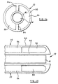
- the stent In an expanded, occluding state, the stent comprises an occluding anchor portion 10 formed by a series of turns of the wire so that a conical helix form is defined.
- the stent further comprises another anchor portion 12 formed by a scroll or spirally wound part of the wire.
- the anchor parts 10 and 12 are interconnected by a straight linking part 14 extending axially of the cone defined by the occluding anchor part 10 and perpendicularly with respect to the plane of the spiral anchor part 12. As can be seen from Fig 1, a single length of wire forms the whole device.
- the stent When the shape memory effect alloy is in a martensitic condition, the stent is malleable and can be deformed into a straight wire W (see Fig 2).
- the wire has a diameter of 0.3mm and is arranged to convert from martensite to austenite at or slightly above 37°C. Such conversion causes the substantially straight length of wire W as illustrated in Fig 2 to convert to the shape illustrated in Fig 1 after release by the delivery system at the desired placement site, as will be described hereinafter.
- the delivery system illustrated therein comprises a catheter 20 having a distal end 22 and a proximal end 24.
- the catheter 20 is closed by a compliant elastomer guide/seal member 26 having a spherically rounded end with a central bore 28 therethrough receiving a distal end of the wire W.
- a proximal end of the wire W is a friction fit within a stainless steel connector bush (see particularly Fig 4) within the catheter 20.
- the connector bush 30 also receives a stainless steel pusher wire 32 extending out of the proximal end 24 of the catheter 20.
- the catheter 20 is provided with cooling liquid inlet and outlet ports 34 and 36, respectively.
- the distal end 22 of the catheter is introduced into the vascular system via a suitable point, such as the femoral artery, and the stent is positioned within the ductus 40 (see Fig. 5) which interconnects the pulmonary artery 42 and the aorta 44 and which is required to be occluded.
- the wire W is maintained in its martensitic form by circulating coolant through the catheter 20 via the ports 34 and 36.
- Ejection of the stent from the catheter 20 is effected by holding the catheter 20 steady whilst pushing on the wire 24 to cause the wire W to be ejected through the member 26 at the distal end 22.
- the stent is ejected, it is warmed by blood at 37 °C, causing the stent to expand so as adopt the structure illustrated in Figs 1 and 5.
- Disengagement of the wire 32 from the stent is effected simply by pulling on the wire 32 so that the bush 30 slides off the wire W which is now firmly anchored in the ductus 40, the strength of the friction fit between the wire W and the bush 30 being sufficient to permit this to take place.
- the strength of the friction fit is such that it can exert a force on the stent which is greater than that required to withdraw a partially deployed stent but less than that required to withdraw a fully deployed stent. In this way, the stent can be controlled and repositioned as well as being finally ejected.
- an alternative arrangement of bush 30 is formed of shape memory alloy material instead of stainless steel.
- the arrangement is such that, upon heating, that portion of the bush 30 which engages the wire W expands into its memorised condition, thereby releasing the wire W.
- the bush 32 is deformed in its low temperature condition by radially compressing or crimping it around the wire W so that it is held firmly.
- the portion of the bush 30 which is engaged with the wire 32 does not have a memory of increased diameter and therefore remains securely attached to the latter.
- the wire 32 can be made from a number of metals that have kink resistance and suitable spring qualities.
- the stent is held in the end of a long plastics tube by an interference fit.
- a wire which is a sliding fit within the plastics tube is used to stiffen the tube and to eject the stent from the end of the plastics tube.
- At least the tip of the catheter at the distal end thereof has a second lumen which allows it to be slipped over and to follow a previously-introduced guide wire.
- the stent illustrated therein consists of a wire formed of two spirally wound anchor parts 10 and 12 interconnected by link part 14 formed of a loop of the length of wire forming the anchor parts 10 and 12.
- link part 14 formed of a loop of the length of wire forming the anchor parts 10 and 12.
- the wire is a thin shape-memory alloy wire where the resilience properties of the spiral coils forming the anchor parts 10 and 12 made from thinner wires means that they will conform to the shape of the vessel in which they are implanted and project as little as possible beyond the vessel.
- the anchor parts 10 and 12 are planar and the link part 14 is a part turn or loop. Alternately, it may be a whole turn or several turns of wire which join the centres of the spiral anchor parts 10 and 12.
- the length of the link part 14 between the anchor parts 10 and 12 will generally be between 0.1 and 5mm.
- the anchor part 10 is cycloidal (Fig 10) or spiral-cycloidal (Fig 11).
- planar anchor portions 10 and 12 When implanted, the planar anchor portions 10 and 12 will be distorted by the walls of the vessels in which the are implanted, yielding an implant which has either two conical anchor portions, two flat anchor portions, or one flat and one conical anchor portion. In all cases, the implant will have been stretched longitudinally and its elastic recoil will ensure that the implant has adopted the minimum length possible within the anatomy and that it therefore projects as little as possible into the vessels on either side of the implant.
- the typical dimensions of the implant are: Maximum diameter of first helix 2mm Minimum diameter of first helix 2mm Number of turns, first helix 10 turns Maximum diameter of second helix 12mm Minimum diameter of second helix 2mm Number of turns, second helix 10 turns Length of connecting part 1mm Wire diameter 0.2mm
- the above typical dimensions may be varied by at least 50% depending upon the extent of biological variation of patients to be fitted with the stent implant.
- the minimum diameter of one or both of the spiral anchor parts 10 and 12 may be less than 2mm, although this figure is limited by the diameter of the wire employed.
- nickel-titanium shape memory alloy wire cannot be completely straightened when it has been formed into a coil of a diameter less than 10 times the diameter of the constituent wire. This limitation may be overcome by constructing the stent implant from thin wire chosen to be approximately one tenth the diameter of the minimum diameter of the spiral anchor part 10 or 12. This results in a simple implant of reduced mechanical strength.
- a multi-stranded wire may be employed made from a number of finer wires twisted or braided together to form the stent implant. This results in a more complex implant of greater mechanical strength.
- the wire shape would be impossible to remove from the mandrel.
- the form can be recovered when the material is warmed above its trigger temperature.
- the shape of the mandrel 50 or 52 defines the number of wire turns in the stent and the diameters of those turns. Once wound onto the mandrel 50 or 52, the wire is fixed at its ends by appropriate clamps or attachment means (not shown). Then, the entire assembly of wire and mandrel is heat-treated so that the wire will adopt the shape imparted by the mandrel when its memory is recovered. This temperature is usually in the region of 350°C to 550°C.
- the wire is removed from the mandrel 50 or 52 and heated gently to make it re-adopt the shape of the mandrel, typically a long spiral whose diameter varies along its length. This is then inserted into a flattening clamp assembly 60 (see Figs 13a and 13b).
- the flattening clamp 60 includes a fixed clamp member 62 from which guide rods 64 extend.
- a movable clamp member 66 and a divider 68 are slidably mounted on the rods 64 and slidable on the rods 64 from an unclamped position as illustrated in Fig 13a to a clamped position as illustrated in Fig 13b.
- the clamp member 62 carries a series of hooks or pegs 69 which are used to trap and retain one or more turns of the spiral in a position which is laterally offset from the axis of the spiral.
- a series of hooks or pegs 69 which are used to trap and retain one or more turns of the spiral in a position which is laterally offset from the axis of the spiral.
- the cycloidal pattern illustrated in Fig 10 can be produced.
- a conically-sided spiral used with the same number of hooks or pegs 69 can produce the less-symmetrical spiral-cycloidal pattern illustrated in Fig 11. If only one hook or peg 69 is used, the entire axis of the trapped spiral can be offset from the untrapped part, resulting in the pattern illustrated in Fig 9.
- Such hooks or pegs 69 may be provided on the clamp member 62 or on the divider 68.
- Pockets 70 are provided in both clamp members 62 and 66. These define the overall length of the sections of the spiral contained within them. Alternatively or additionally, one or more of the pockets 70 may be provided in the appropriate surface or surfaces of the divider 68. In a further embodiment, the divider 68 may be omitted completely, or more than one divider 68 may be provided. When no dividers 68 are used, a flat spiral of zero longitudinal pitch is produced. The divider or dividers can be introduced to define the longitudinal pitch of particular turns of the spiral.
- the catheter illustrated therein comprises outer and inner walls 80 and 82 which are maintained in spaced apart relationship by a pair of internal ribs 84 which divide the area between the walls 80 and 82 longitudinally into feed and return passages 86 and 88 for cooling liquid. These ribs are removed at the distal end 22 of the catheter 20 so as to allow the liquid from the feed passage 86 to return via the passage 88.
Landscapes
- Health & Medical Sciences (AREA)
- Life Sciences & Earth Sciences (AREA)
- Surgery (AREA)
- Biomedical Technology (AREA)
- Public Health (AREA)
- Engineering & Computer Science (AREA)
- Heart & Thoracic Surgery (AREA)
- Veterinary Medicine (AREA)
- Animal Behavior & Ethology (AREA)
- General Health & Medical Sciences (AREA)
- Vascular Medicine (AREA)
- Medical Informatics (AREA)
- Nuclear Medicine, Radiotherapy & Molecular Imaging (AREA)
- Molecular Biology (AREA)
- Reproductive Health (AREA)
- Cardiology (AREA)
- Oral & Maxillofacial Surgery (AREA)
- Transplantation (AREA)
- Media Introduction/Drainage Providing Device (AREA)
- Prostheses (AREA)
Claims (18)
- Stent zur chirurgischen Implantation in einen Patienten, wobei der Stent über einen Draht (W) verfügt, der von einem relativ gestreckten Zustand für das Einführen in den Patienten in einen Okklusionszustand expandierbar ist, in dem er einen okkludierenden Verankerungsteil (10) bildet, innerhalb desselben der Draht (W) eine Reihe von Windungen eingenommen hat, die sich über die Querschnittsfläche des okkludierenden Verankerungsteils (10) erstrecken, dadurch gekennzeichnet, dass die Drahtwindungen im okkludierenden Verankerungsteil (10) von(a) Zykloidform sind, die dadurch erzeugbar ist, dass einzelne Windungen einer zylindrischen Helix lateral in verschiedenen Richtungen verschoben werden und sie dadurch so abgeflacht werden, dass sie im Wesentlichen koplanar sind; oder(b) eine Spirozykloidform einnehmen, die dadurch erzeugbar ist, dass einzelne Windungen einer sich verjüngenden Helix lateral in verschiedenen Richtungen verschoben werden und sie dadurch so abgeflacht werden, dass sie im Wesentlichen koplanar sind.
- Stent nach Anspruch 1, bei dem die Drahtwindungen im okkludierenden Verankerungsteil (10) die genannte Zykloidform einnehmen.
- Stent nach Anspruch 1, bei dem die Drahtwindungen im okkludierenden Verankerungsteil (10) die genannte Spirozykloidform einnehmen.
- Stent nach Anspruch 1, 2 oder 3, bei dem der Draht (W) aus einem Material mit Formspeichereffekt besteht und er über einer vorbestimmten Triggertemperatur von selbst in seinen Okklusionszustand expandiert.
- Stent nach Anspruch 1, 2 oder 3, bei dem der Draht (W) aus einem superelastischen Material besteht, das elastisch in seinen Okklusionszustand vorgespannt ist und das in relativ gestrecktem Zustand gehalten werden kann.
- Stent nach einem der vorstehenden Ansprüche, bei dem der Draht (W) in seinem Okklusionszustand auch einen anderen Verankerungsteil (12) bildet, der vom okkludierenden Verankerungsteil (6) beabstandet ist und mit diesem über einen Verbindungsteil (14) verbunden ist.
- Stent nach Anspruch 6, bei dem der andere Verankerungsteil (12) aus einem Draht (W) mit einer Reihe von Windungen besteht, die sich lateral in Bezug auf den Verbindungsteil (14) erstrecken.
- Stent nach Anspruch 7, bei dem sich die Drahtwindungen über die Querschnittsfläche des anderen Verankerungsteils (12) erstrecken.
- Stent nach Anspruch 7 oder 8, bei dem die Drahtwindungen des anderen Verankerungsteils (14) nicht mit den Drahtwindungen des okkludierenden Verankerungsteils (12) in der Trennungsrichtung der Verankerungsteile (10 und 12) ausgerichtet ist.
- Stent nach einem der Ansprüche 7 bis 9, bei dem die Drahtwindungen im anderen Verankerungsteil (14) im Wesentlichen Kegelform, Schnecken- oder Spiralform, Zykloidform oder Spirozykloidform aufweisen.
- Stent nach einem der vorstehenden Ansprüche, bei dem zumindest ein Teil des Drahts (W) mit einer pharmakologischen Beschichtung beschichtet ist.
- Stent nach Anspruch 11, bei dem die Beschichtung aus einem Protein besteht, das Blutgerinnung und Zellenanhaftung startet.
- Stent nach einem der vorstehenden Ansprüche, bei dem zumindest ein Teil des Drahts (W) über eine aufgeraute Oberfläche verfügt.
- Einführsystem zum Platzieren eines Stents nach einem der Ansprüche 1 bis 13, das über einen Katheter zum Aufnehmen des Stents in gestrecktem Zustand, ein längliches, flexibles Platzierungselement (32) für die Streckung, oder das so ausgebildet ist, dass es sich in der Längsrichtung des Katheters erstreckt und über ein proximales und ein distales Ende verfügt, und eine lösbare Verbindungseinrichtung (30) aufweist, die das distale Ende des Platzierungselements (32) mit dem Stent verbindet oder so ausgebildet ist, dass sie die beiden verbinden kann, dadurch gekennzeichnet, dass die lösbare Verbindungseinrichtung eine Hülse ist, die dazu geeignet ist, reibungsmäßig zum Ende des Drahts (W) zu passen und von diesem Draht durch Zug herunter zu gleiten, wenn der Stent. fest verankert ist.
- Trennbarer Verbinder (30) zum trennbaren Verbinden eines Stents mit einem länglichen, flexiblen Platzierungselement (32) zum Einführen des Stents in einen Körperbereich, wobei der Verbinder einen ersten und einen zweiten Verbinderbereich für Befestigung am Stent bzw. am genannten Element (32) aufweist, dadurch gekennzeichnet, dass der Stent dergestalt ist, wie es in einem der Ansprüche 1 bis 13 beansprucht ist, und der Verbinder eine Hülse gemäß dem Anspruch 14 ist, und dass der erste Verbinderbereich einen Formspeichereffekt aufweist und über einer vorbestimmten Triggertemperatur von einem ersten in einen zweiten Zustand änderbar ist, wobei der erste Zustand ein solcher ist, in dem der erste Verbinderbereich den Stent durch Reibung hält, und der zweite Zustand ein solcher ist, in dem der erste Verbinderbereich so ausgebildet ist, dass er den Stent freigibt, um es zu ermöglichen, den Stent und das Element zu trennen.
- Trennbarer Verbinder nach Anspruch 15, bei dem der erste Verbinderbereich einen ersten Hülsenteil aufweist, der so ausgebildet ist, dass er, in seinem ersten Zustand, den Stent aufnimmt und hält.
- Trennbarer Verbinder nach Anspruch 15 oder 16, bei dem der zweite Verbinderbereich einen zweiten Hülsenteil aufweist, der so ausgebildet ist, dass er das Element (30) aufnimmt und hält, wenn sich der erste Verbinderbereich in seinem ersten oder zweiten Zustand befindet.
- Verfahren zum Herstellen eines Stents nach einem der Ansprüche 1 bis 13, mit den folgenden Schritten: (a) Aufwickeln eines Stücks Draht aus einem Formspeichermaterial auf einen doppelkegelstumpfförmigen oder kegelförmig-zylindrischen Dorn (50 oder 52) zum Erzeugen einer Reihe von Windungen, die einen Windungsbereich mit Längserstreckung bilden; (b) Behandeln des auf den Dorn (50 oder 52) gewickelten Drahts (W), um darin ein Formgedächtnis des Windungsbereichs einzustellen; (c) Abnehmen des aufgewickelten Drahts (W) vom Dorn (50 oder 52); (d) Behandeln des entnommenen Drahts (W), um die Gedächtnisform des Windungsbereichs wiederherzustellen; (e) Verringern der Länge des Windungsbereichs in solcher Weise, dass er im Wesentlichen planar ist; und (f) Behandeln des Drahts (W), um darin ein Gedächtnis für die geänderte Form des Windungsbereichs einzustellen; und (g) Verschieben, zwischen den Schritten (d) und (f), einer oder mehrerer der den Windungsbereich bildenden Windungen lateral zur Richtung der Längserstreckung des Windungsbereichs, um dadurch den okkludierenden Verankerungsteil (12) durch Drahtwindungen der Zykloidform oder der Spirozykloidform zu bilden.
Applications Claiming Priority (3)
| Application Number | Priority Date | Filing Date | Title |
|---|---|---|---|
| GBGB9614950.5A GB9614950D0 (en) | 1996-07-16 | 1996-07-16 | A ductus stent and delivery catheter |
| GB9614950 | 1996-07-16 | ||
| PCT/GB1997/001899 WO1998002100A1 (en) | 1996-07-16 | 1997-07-15 | Surgical implants and delivery systems therefor |
Publications (2)
| Publication Number | Publication Date |
|---|---|
| EP0915678A1 EP0915678A1 (de) | 1999-05-19 |
| EP0915678B1 true EP0915678B1 (de) | 2003-06-25 |
Family
ID=10797015
Family Applications (1)
| Application Number | Title | Priority Date | Filing Date |
|---|---|---|---|
| EP97931921A Expired - Lifetime EP0915678B1 (de) | 1996-07-16 | 1997-07-15 | Chirurgische implantate und deren anbringungssysteme |
Country Status (9)
| Country | Link |
|---|---|
| US (2) | US6432134B1 (de) |
| EP (1) | EP0915678B1 (de) |
| JP (1) | JP2000514336A (de) |
| AU (1) | AU3550897A (de) |
| CA (1) | CA2261044C (de) |
| DE (1) | DE69723080T2 (de) |
| ES (1) | ES2202627T3 (de) |
| GB (1) | GB9614950D0 (de) |
| WO (1) | WO1998002100A1 (de) |
Families Citing this family (241)
| Publication number | Priority date | Publication date | Assignee | Title |
|---|---|---|---|---|
| US6083220A (en) | 1990-03-13 | 2000-07-04 | The Regents Of The University Of California | Endovascular electrolytically detachable wire and tip for the formation of thrombus in arteries, veins, aneurysms, vascular malformations and arteriovenous fistulas |
| USRE42625E1 (en) | 1990-03-13 | 2011-08-16 | The Regents Of The University Of California | Endovascular electrolytically detachable wire and tip for the formation of thrombus in arteries, veins, aneurysms, vascular malformations and arteriovenous fistulas |
| USRE42756E1 (en) | 1990-03-13 | 2011-09-27 | The Regents Of The University Of California | Endovascular electrolytically detachable wire and tip for the formation of thrombus in arteries, veins, aneurysms, vascular malformations and arteriovenous fistulas |
| US5350397A (en) | 1992-11-13 | 1994-09-27 | Target Therapeutics, Inc. | Axially detachable embolic coil assembly |
| US5800453A (en) * | 1993-04-19 | 1998-09-01 | Target Therapeutics, Inc. | Detachable embolic coil assembly using interlocking hooks and slots |
| US5814062A (en) | 1994-12-22 | 1998-09-29 | Target Therapeutics, Inc. | Implant delivery assembly with expandable coupling/decoupling mechanism |
| US6949116B2 (en) * | 1996-05-08 | 2005-09-27 | Carag Ag | Device for plugging an opening such as in a wall of a hollow or tubular organ including biodegradable elements |
| DK177010B1 (da) * | 1996-09-03 | 2010-11-29 | Cook William Europ | Embolisationsindretning til placering i et blodkar |
| US6984240B1 (en) | 1996-10-25 | 2006-01-10 | Target Therapeutics, Inc. | Detachable multidiameter vasoocclusive coil |
| US6951572B1 (en) | 1997-02-20 | 2005-10-04 | Endologix, Inc. | Bifurcated vascular graft and method and apparatus for deploying same |
| WO1998047430A1 (en) * | 1997-04-23 | 1998-10-29 | Vascular Science Inc. | Medical plug |
| US5984929A (en) * | 1997-08-29 | 1999-11-16 | Target Therapeutics, Inc. | Fast detaching electronically isolated implant |
| US6156061A (en) | 1997-08-29 | 2000-12-05 | Target Therapeutics, Inc. | Fast-detaching electrically insulated implant |
| US6136015A (en) * | 1998-08-25 | 2000-10-24 | Micrus Corporation | Vasoocclusive coil |
| US6475227B2 (en) | 1997-12-24 | 2002-11-05 | Scimed Life Systems, Inc. | Vaso-occlusion apparatus having a mechanically expandable detachment joint and a method for using the apparatus |
| US7520890B2 (en) * | 1998-01-26 | 2009-04-21 | Phillips Peter W | Reinforced graft and method of deployment |
| US5944738A (en) | 1998-02-06 | 1999-08-31 | Aga Medical Corporation | Percutaneous catheter directed constricting occlusion device |
| US5935145A (en) | 1998-02-13 | 1999-08-10 | Target Therapeutics, Inc. | Vaso-occlusive device with attached polymeric materials |
| US5941888A (en) | 1998-02-18 | 1999-08-24 | Target Therapeutics, Inc. | Vaso-occlusive member assembly with multiple detaching points |
| US6077260A (en) | 1998-02-19 | 2000-06-20 | Target Therapeutics, Inc. | Assembly containing an electrolytically severable joint for endovascular embolic devices |
| US6063100A (en) * | 1998-03-10 | 2000-05-16 | Cordis Corporation | Embolic coil deployment system with improved embolic coil |
| US6183491B1 (en) | 1998-03-10 | 2001-02-06 | Cordis Corporation | Embolic coil deployment system with improved embolic coil |
| US6379374B1 (en) | 1998-10-22 | 2002-04-30 | Cordis Neurovascular, Inc. | Small diameter embolic coil hydraulic deployment system |
| US6068644A (en) * | 1998-03-10 | 2000-05-30 | Cordis Corporation | Embolic coil hydraulic deployment system having improved catheter |
| US6113622A (en) * | 1998-03-10 | 2000-09-05 | Cordis Corporation | Embolic coil hydraulic deployment system |
| DK1100381T3 (da) | 1998-08-03 | 2005-12-19 | Anson Medical Ltd | Indretning til reparation af arterier |
| US6149664A (en) * | 1998-08-27 | 2000-11-21 | Micrus Corporation | Shape memory pusher introducer for vasoocclusive devices |
| US6254612B1 (en) | 1998-10-22 | 2001-07-03 | Cordis Neurovascular, Inc. | Hydraulic stent deployment system |
| US7044134B2 (en) | 1999-11-08 | 2006-05-16 | Ev3 Sunnyvale, Inc | Method of implanting a device in the left atrial appendage |
| US6660030B2 (en) | 1998-12-11 | 2003-12-09 | Endologix, Inc. | Bifurcation graft deployment catheter |
| US6102932A (en) | 1998-12-15 | 2000-08-15 | Micrus Corporation | Intravascular device push wire delivery system |
| US6261316B1 (en) | 1999-03-11 | 2001-07-17 | Endologix, Inc. | Single puncture bifurcation graft deployment system |
| US8034100B2 (en) | 1999-03-11 | 2011-10-11 | Endologix, Inc. | Graft deployment system |
| JP2000300571A (ja) | 1999-04-19 | 2000-10-31 | Nissho Corp | 経カテーテル手術用閉鎖栓 |
| US6231561B1 (en) | 1999-09-20 | 2001-05-15 | Appriva Medical, Inc. | Method and apparatus for closing a body lumen |
| US6689150B1 (en) | 1999-10-27 | 2004-02-10 | Atritech, Inc. | Filter apparatus for ostium of left atrial appendage |
| US6551303B1 (en) | 1999-10-27 | 2003-04-22 | Atritech, Inc. | Barrier device for ostium of left atrial appendage |
| US6790218B2 (en) * | 1999-12-23 | 2004-09-14 | Swaminathan Jayaraman | Occlusive coil manufacture and delivery |
| DE10000137A1 (de) * | 2000-01-04 | 2001-07-12 | Pfm Prod Fuer Die Med Ag | Implantat zum Verschließen von Defektöffnungen im menschlichen oder tierischen Körper |
| US6602280B2 (en) | 2000-02-02 | 2003-08-05 | Trivascular, Inc. | Delivery system and method for expandable intracorporeal device |
| GB2359024A (en) | 2000-02-09 | 2001-08-15 | Anson Medical Ltd | Fixator for arteries |
| US6544225B1 (en) | 2000-02-29 | 2003-04-08 | Cordis Neurovascular, Inc. | Embolic coil hydraulic deployment system with purge mechanism |
| AU2001241909A1 (en) * | 2000-03-03 | 2001-09-17 | Timothy A.M. Chuter | Large vessel stents and occluders |
| AU2000266318A1 (en) * | 2000-08-10 | 2002-02-25 | Micrus Corporation | Intravascular delivery system |
| IL155015A0 (en) | 2000-09-21 | 2003-10-31 | Atritech Inc | Apparatus for implanting devices in atrial appendages |
| US7029486B2 (en) | 2000-09-26 | 2006-04-18 | Microvention, Inc. | Microcoil vaso-occlusive device with multi-axis secondary configuration |
| US7033374B2 (en) * | 2000-09-26 | 2006-04-25 | Microvention, Inc. | Microcoil vaso-occlusive device with multi-axis secondary configuration |
| US6605101B1 (en) | 2000-09-26 | 2003-08-12 | Microvention, Inc. | Microcoil vaso-occlusive device with multi-axis secondary configuration |
| US6635069B1 (en) * | 2000-10-18 | 2003-10-21 | Scimed Life Systems, Inc. | Non-overlapping spherical three-dimensional coil |
| US6846319B2 (en) | 2000-12-14 | 2005-01-25 | Core Medical, Inc. | Devices for sealing openings through tissue and apparatus and methods for delivering them |
| US8083768B2 (en) | 2000-12-14 | 2011-12-27 | Ensure Medical, Inc. | Vascular plug having composite construction |
| US6896692B2 (en) | 2000-12-14 | 2005-05-24 | Ensure Medical, Inc. | Plug with collet and apparatus and method for delivering such plugs |
| DE10107795B4 (de) * | 2001-02-13 | 2014-05-15 | Berlex Ag | Gefäßstütze mit einem Grundkörper, Verfahren zur Herstellung der Gefäßstütze, Vorrichtung zur Beschichtung der Gefäßstütze |
| EP1365702A2 (de) * | 2001-03-08 | 2003-12-03 | Atritech, Inc. | Herzvorhof filter implantate |
| US6761733B2 (en) | 2001-04-11 | 2004-07-13 | Trivascular, Inc. | Delivery system and method for bifurcated endovascular graft |
| US6733521B2 (en) | 2001-04-11 | 2004-05-11 | Trivascular, Inc. | Delivery system and method for endovascular graft |
| GB0110670D0 (en) * | 2001-05-01 | 2001-06-20 | Anson Medical Ltd | Machine for manufacturing graft-stents |
| CA2449468A1 (en) | 2001-06-04 | 2002-12-12 | Albert Einstein Healthcare Network | Cardiac stimulating apparatus having a blood clot filter and atrial pacer |
| US6953468B2 (en) * | 2001-06-13 | 2005-10-11 | Cordis Neurovascular, Inc. | Occluding vasculature of a patient using embolic coil with improved platelet adhesion |
| US7011671B2 (en) | 2001-07-18 | 2006-03-14 | Atritech, Inc. | Cardiac implant device tether system and method |
| US7669799B2 (en) * | 2001-08-24 | 2010-03-02 | University Of Virginia Patent Foundation | Reversible shape memory multifunctional structural designs and method of using and making the same |
| US20060052821A1 (en) | 2001-09-06 | 2006-03-09 | Ovalis, Inc. | Systems and methods for treating septal defects |
| US6702835B2 (en) | 2001-09-07 | 2004-03-09 | Core Medical, Inc. | Needle apparatus for closing septal defects and methods for using such apparatus |
| US6776784B2 (en) | 2001-09-06 | 2004-08-17 | Core Medical, Inc. | Clip apparatus for closing septal defects and methods of use |
| US6811560B2 (en) | 2001-09-20 | 2004-11-02 | Cordis Neurovascular, Inc. | Stent aneurysm embolization method and device |
| US6802851B2 (en) | 2001-09-20 | 2004-10-12 | Gordia Neurovascular, Inc. | Stent aneurysm embolization method using collapsible member and embolic coils |
| US20100016943A1 (en) | 2001-12-20 | 2010-01-21 | Trivascular2, Inc. | Method of delivering advanced endovascular graft |
| US7147661B2 (en) | 2001-12-20 | 2006-12-12 | Boston Scientific Santa Rosa Corp. | Radially expandable stent |
| AU2002360765C1 (en) | 2001-12-20 | 2009-06-11 | Trivascular, Inc. | Advanced endovascular graft |
| US6981985B2 (en) | 2002-01-22 | 2006-01-03 | Boston Scientific Scimed, Inc. | Stent bumper struts |
| CN1638703A (zh) | 2002-01-25 | 2005-07-13 | 阿特里泰克公司 | 心房附件血液过滤系统 |
| WO2003101722A1 (en) | 2002-05-30 | 2003-12-11 | University Of Virginia Patent Foundation | Active energy absorbing cellular metals and method of manufacturing and using the same |
| WO2004012603A2 (en) * | 2002-07-31 | 2004-02-12 | Abbott Laboratories Vascular Enterprises, Limited | Apparatus for sealing surgical punctures |
| GB0220340D0 (en) | 2002-09-02 | 2002-10-09 | Anson Medical Ltd | Flexible stent-graft |
| AU2003280278A1 (en) * | 2002-11-27 | 2004-06-18 | Carag Ag | An implant for occluding a passage |
| DE10302447B4 (de) * | 2003-01-21 | 2007-12-06 | pfm Produkte für die Medizin AG | Okklusionseinrichtung, Platziersystem, Set aus einem derartigen Platziersystem und einer derartigen Okklusionseinrichtung sowie Verfahren zur Herstellung einer Okklusionseinrichtung |
| US9861346B2 (en) | 2003-07-14 | 2018-01-09 | W. L. Gore & Associates, Inc. | Patent foramen ovale (PFO) closure device with linearly elongating petals |
| US8852229B2 (en) | 2003-10-17 | 2014-10-07 | Cordis Corporation | Locator and closure device and method of use |
| US20050273119A1 (en) * | 2003-12-09 | 2005-12-08 | Nmt Medical, Inc. | Double spiral patent foramen ovale closure clamp |
| US20050161549A1 (en) * | 2003-12-30 | 2005-07-28 | Hainline Truman D. | Coil winding machine |
| ES2289478T3 (es) * | 2004-02-04 | 2008-02-01 | Carag Ag | Implante para cerrar un paso corporal de un cuerpo humano. |
| GB0402796D0 (en) * | 2004-02-09 | 2004-03-10 | Anson Medical Ltd | An endoluminal surgical delivery system |
| US9039724B2 (en) * | 2004-03-19 | 2015-05-26 | Aga Medical Corporation | Device for occluding vascular defects |
| US8777974B2 (en) * | 2004-03-19 | 2014-07-15 | Aga Medical Corporation | Multi-layer braided structures for occluding vascular defects |
| US8398670B2 (en) | 2004-03-19 | 2013-03-19 | Aga Medical Corporation | Multi-layer braided structures for occluding vascular defects and for occluding fluid flow through portions of the vasculature of the body |
| US8747453B2 (en) * | 2008-02-18 | 2014-06-10 | Aga Medical Corporation | Stent/stent graft for reinforcement of vascular abnormalities and associated method |
| US7842053B2 (en) * | 2004-05-06 | 2010-11-30 | Nmt Medical, Inc. | Double coil occluder |
| US8257389B2 (en) * | 2004-05-07 | 2012-09-04 | W.L. Gore & Associates, Inc. | Catching mechanisms for tubular septal occluder |
| AT501408B1 (de) | 2004-12-07 | 2011-03-15 | Physikalisches Buero Steinmueller Gmbh | Biologische oberflächen |
| US20080021497A1 (en) * | 2005-01-03 | 2008-01-24 | Eric Johnson | Endoluminal filter |
| US7998164B2 (en) * | 2005-03-11 | 2011-08-16 | Boston Scientific Scimed, Inc. | Intravascular filter with centering member |
| JP4951503B2 (ja) * | 2005-03-29 | 2012-06-13 | テルモ株式会社 | 欠損閉鎖デバイス |
| US8926654B2 (en) | 2005-05-04 | 2015-01-06 | Cordis Corporation | Locator and closure device and method of use |
| EP2135560B1 (de) | 2005-06-02 | 2011-08-10 | Cordis Corporation | Medizinische Vorrichtung zum Einsatz einer mechanischen Verschlusseinrichtung |
| US8579936B2 (en) | 2005-07-05 | 2013-11-12 | ProMed, Inc. | Centering of delivery devices with respect to a septal defect |
| US7846179B2 (en) | 2005-09-01 | 2010-12-07 | Ovalis, Inc. | Suture-based systems and methods for treating septal defects |
| CA2621197A1 (en) | 2005-09-01 | 2007-03-08 | Cordis Corporation | Patent foramen ovale closure method |
| US7972359B2 (en) | 2005-09-16 | 2011-07-05 | Atritech, Inc. | Intracardiac cage and method of delivering same |
| US8020275B2 (en) * | 2005-11-17 | 2011-09-20 | The Cleveland Clinic Foundation | Method for compressing intraluminal prostheses |
| US20070191931A1 (en) * | 2006-02-16 | 2007-08-16 | Jan Weber | Bioerodible endoprostheses and methods of making the same |
| US9526814B2 (en) * | 2006-02-16 | 2016-12-27 | Boston Scientific Scimed, Inc. | Medical balloons and methods of making the same |
| US20070225759A1 (en) * | 2006-03-22 | 2007-09-27 | Daniel Thommen | Method for delivering a medical device to the heart of a patient |
| DE102006036649A1 (de) * | 2006-04-27 | 2007-10-31 | Biophan Europe Gmbh | Okkluder |
| US8360361B2 (en) | 2006-05-23 | 2013-01-29 | University Of Virginia Patent Foundation | Method and apparatus for jet blast deflection |
| US7963942B2 (en) * | 2006-09-20 | 2011-06-21 | Boston Scientific Scimed, Inc. | Medical balloons with modified surfaces |
| CA2664686C (en) | 2006-09-29 | 2015-06-02 | Cardinal Health 529, Llc | Single disc intraluminal fixation patent foramen ovale closure device |
| US8523931B2 (en) | 2007-01-12 | 2013-09-03 | Endologix, Inc. | Dual concentric guidewire and methods of bifurcated graft deployment |
| US9005242B2 (en) | 2007-04-05 | 2015-04-14 | W.L. Gore & Associates, Inc. | Septal closure device with centering mechanism |
| FR2915087B1 (fr) * | 2007-04-20 | 2021-11-26 | Corevalve Inc | Implant de traitement d'une valve cardiaque, en particulier d'une valve mitrale, materiel inculant cet implant et materiel de mise en place de cet implant. |
| US8003157B2 (en) | 2007-06-15 | 2011-08-23 | Abbott Cardiovascular Systems Inc. | System and method for coating a stent |
| US8677650B2 (en) * | 2007-06-15 | 2014-03-25 | Abbott Cardiovascular Systems Inc. | Methods and devices for drying coated stents |
| DE102007032339B4 (de) * | 2007-07-11 | 2010-03-25 | Acandis Gmbh & Co. Kg | Vorrichtung zum Verschließen von Gefäßaneurysmen |
| US8034061B2 (en) * | 2007-07-12 | 2011-10-11 | Aga Medical Corporation | Percutaneous catheter directed intravascular occlusion devices |
| US8066755B2 (en) | 2007-09-26 | 2011-11-29 | Trivascular, Inc. | System and method of pivoted stent deployment |
| US8226701B2 (en) | 2007-09-26 | 2012-07-24 | Trivascular, Inc. | Stent and delivery system for deployment thereof |
| US8663309B2 (en) | 2007-09-26 | 2014-03-04 | Trivascular, Inc. | Asymmetric stent apparatus and method |
| AU2008308474B2 (en) | 2007-10-04 | 2014-07-24 | Trivascular, Inc. | Modular vascular graft for low profile percutaneous delivery |
| US20090112311A1 (en) * | 2007-10-19 | 2009-04-30 | Coherex Medical, Inc. | Medical device for percutaneous paravalvular leak and related systems and methods |
| US8328861B2 (en) | 2007-11-16 | 2012-12-11 | Trivascular, Inc. | Delivery system and method for bifurcated graft |
| US8083789B2 (en) | 2007-11-16 | 2011-12-27 | Trivascular, Inc. | Securement assembly and method for expandable endovascular device |
| US8221494B2 (en) | 2008-02-22 | 2012-07-17 | Endologix, Inc. | Apparatus and method of placement of a graft or graft system |
| US20130165967A1 (en) | 2008-03-07 | 2013-06-27 | W.L. Gore & Associates, Inc. | Heart occlusion devices |
| US8236040B2 (en) | 2008-04-11 | 2012-08-07 | Endologix, Inc. | Bifurcated graft deployment systems and methods |
| US8323335B2 (en) | 2008-06-20 | 2012-12-04 | Edwards Lifesciences Corporation | Retaining mechanisms for prosthetic valves and methods for using |
| EP2520320B1 (de) | 2008-07-01 | 2016-11-02 | Endologix, Inc. | Kathetersystem |
| US8162958B2 (en) | 2008-07-11 | 2012-04-24 | Olympus Medical Systems Corp. | Tissue fastening tool and applicator for indwelling the same within body, and tissue fastening method through natural orifice |
| US20100010520A1 (en) * | 2008-07-11 | 2010-01-14 | Olympus Medical Systems Corp. | Tissue fastener |
| US8828026B2 (en) | 2008-07-11 | 2014-09-09 | Olympus Medical Systems Corp. | Tissue fastening apparatus |
| DE102008034534A1 (de) * | 2008-07-18 | 2010-01-21 | Aesculap Ag | Punktionsverschluss zum Verschließen eines eine Punktionsöffnung aufweisenden Hohlorgans, insbesondere eines Blutgefäßes |
| US8905961B2 (en) * | 2008-12-19 | 2014-12-09 | St. Jude Medical, Inc. | Systems, apparatuses, and methods for cardiovascular conduits and connectors |
| IL197800A0 (en) * | 2009-03-25 | 2009-12-24 | Shmuel Ben Muvhar | Internal filtering device |
| JP5629871B2 (ja) | 2009-04-28 | 2014-11-26 | エンドロジックス、インク | 移植片あるいは移植片システムを配置する装置および方法 |
| EP2424447A2 (de) | 2009-05-01 | 2012-03-07 | Endologix, Inc. | Perkutanes verfahren und vorrichtung zur behandlung von dissektionen |
| US10772717B2 (en) | 2009-05-01 | 2020-09-15 | Endologix, Inc. | Percutaneous method and device to treat dissections |
| AU2010254151B2 (en) * | 2009-05-28 | 2013-11-28 | Cook Medical Technologies Llc | Tacking device and methods of deployment |
| US9636094B2 (en) | 2009-06-22 | 2017-05-02 | W. L. Gore & Associates, Inc. | Sealing device and delivery system |
| US20120029556A1 (en) | 2009-06-22 | 2012-02-02 | Masters Steven J | Sealing device and delivery system |
| US8491646B2 (en) | 2009-07-15 | 2013-07-23 | Endologix, Inc. | Stent graft |
| ES2549000T3 (es) | 2009-07-27 | 2015-10-22 | Endologix, Inc. | Endoprótesis |
| EP3335670B1 (de) | 2010-03-05 | 2022-05-04 | Edwards Lifesciences Corporation | Haltemechanismen für klappenprothesen |
| US9017351B2 (en) | 2010-06-29 | 2015-04-28 | Artventive Medical Group, Inc. | Reducing flow through a tubular structure |
| US9247942B2 (en) | 2010-06-29 | 2016-02-02 | Artventive Medical Group, Inc. | Reversible tubal contraceptive device |
| US8657872B2 (en) | 2010-07-19 | 2014-02-25 | Jacques Seguin | Cardiac valve repair system and methods of use |
| ES3023659T3 (en) | 2010-07-23 | 2025-06-02 | Edwards Lifesciences Corp | Retaining mechanisms for prosthetic valves |
| US9149277B2 (en) | 2010-10-18 | 2015-10-06 | Artventive Medical Group, Inc. | Expandable device delivery |
| EP2635241B1 (de) | 2010-11-02 | 2019-02-20 | Endologix, Inc. | Vorrichtung zur positionierung einer gefässprothese bzw. eines gefässprothesensystems |
| WO2012068298A1 (en) | 2010-11-17 | 2012-05-24 | Endologix, Inc. | Devices and methods to treat vascular dissections |
| US8489649B2 (en) | 2010-12-13 | 2013-07-16 | Oracle International Corporation | Extensible RDF databases |
| CN103561807B (zh) | 2011-03-01 | 2015-11-25 | 恩朵罗杰克斯股份有限公司 | 导管系统及其使用方法 |
| EP3031428B1 (de) | 2011-03-08 | 2020-11-18 | W.L. Gore & Associates, Inc | Medizinische vorrichtung zur verwendung mit einem stoma |
| US9770232B2 (en) | 2011-08-12 | 2017-09-26 | W. L. Gore & Associates, Inc. | Heart occlusion devices |
| WO2013070686A1 (en) | 2011-11-08 | 2013-05-16 | Boston Scientific Scimed, Inc. | Handle assembly for a left atrial appendage occlusion device |
| US9078747B2 (en) | 2011-12-21 | 2015-07-14 | Edwards Lifesciences Corporation | Anchoring device for replacing or repairing a heart valve |
| US10426501B2 (en) | 2012-01-13 | 2019-10-01 | Crux Biomedical, Inc. | Retrieval snare device and method |
| CA3208176A1 (en) | 2012-01-31 | 2013-08-08 | Mitral Valve Technologies Sarl | Mitral valve docking devices, systems and methods |
| US10213288B2 (en) | 2012-03-06 | 2019-02-26 | Crux Biomedical, Inc. | Distal protection filter |
| US8992595B2 (en) | 2012-04-04 | 2015-03-31 | Trivascular, Inc. | Durable stent graft with tapered struts and stable delivery methods and devices |
| US9498363B2 (en) | 2012-04-06 | 2016-11-22 | Trivascular, Inc. | Delivery catheter for endovascular device |
| US9173753B1 (en) | 2012-05-11 | 2015-11-03 | W. L. Gore & Associates, Inc. | System and method for forming an endoluminal device |
| US9085054B2 (en) | 2012-12-21 | 2015-07-21 | Cook Medical Technologies Llc | Method of texturing an inner surface of a self-expanding implant delivery system outer sheath |
| US9439661B2 (en) | 2013-01-09 | 2016-09-13 | Covidien Lp | Connection of a manipulation member, including a bend without substantial surface cracks, to an endovascular intervention device |
| US10828019B2 (en) | 2013-01-18 | 2020-11-10 | W.L. Gore & Associates, Inc. | Sealing device and delivery system |
| US9095344B2 (en) | 2013-02-05 | 2015-08-04 | Artventive Medical Group, Inc. | Methods and apparatuses for blood vessel occlusion |
| US8984733B2 (en) | 2013-02-05 | 2015-03-24 | Artventive Medical Group, Inc. | Bodily lumen occlusion |
| US9737306B2 (en) | 2013-06-14 | 2017-08-22 | Artventive Medical Group, Inc. | Implantable luminal devices |
| US10149968B2 (en) | 2013-06-14 | 2018-12-11 | Artventive Medical Group, Inc. | Catheter-assisted tumor treatment |
| US9737308B2 (en) | 2013-06-14 | 2017-08-22 | Artventive Medical Group, Inc. | Catheter-assisted tumor treatment |
| US9636116B2 (en) | 2013-06-14 | 2017-05-02 | Artventive Medical Group, Inc. | Implantable luminal devices |
| SG10202103500PA (en) | 2013-08-12 | 2021-05-28 | Mitral Valve Tech Sarl | Apparatus and methods for implanting a replacement heart valve |
| EP4578426A3 (de) | 2013-08-14 | 2025-09-03 | Mitral Valve Technologies Sàrl | Ersatzherzklappenvorrichtung und verfahren |
| US10195028B2 (en) | 2013-09-10 | 2019-02-05 | Edwards Lifesciences Corporation | Magnetic retaining mechanisms for prosthetic valves |
| GB2523291B (en) * | 2013-10-16 | 2016-02-24 | Cook Medical Technologies Llc | Vascular occluder with crossing frame elements |
| US9622863B2 (en) | 2013-11-22 | 2017-04-18 | Edwards Lifesciences Corporation | Aortic insufficiency repair device and method |
| US10350098B2 (en) | 2013-12-20 | 2019-07-16 | Volcano Corporation | Devices and methods for controlled endoluminal filter deployment |
| US9730701B2 (en) | 2014-01-16 | 2017-08-15 | Boston Scientific Scimed, Inc. | Retrieval wire centering device |
| ES3037253T3 (en) | 2014-02-20 | 2025-09-30 | Mitral Valve Tech Sarl | A system for implanting a prosthetic heart valve supported by a coiled anchor |
| EP3107498B1 (de) | 2014-02-21 | 2020-09-30 | Mitral Valve Technologies Sàrl | Künstliche mitralklappe mit verankerungsvorrichtung |
| US10363043B2 (en) | 2014-05-01 | 2019-07-30 | Artventive Medical Group, Inc. | Treatment of incompetent vessels |
| US11439396B2 (en) | 2014-05-02 | 2022-09-13 | W. L. Gore & Associates, Inc. | Occluder and anastomosis devices |
| US10004509B2 (en) | 2014-05-02 | 2018-06-26 | W. L. Gore & Associates, Inc. | Anastomosis devices |
| US11712230B2 (en) | 2014-05-02 | 2023-08-01 | W. L. Gore & Associates, Inc. | Occluder and anastomosis devices |
| US9808230B2 (en) | 2014-06-06 | 2017-11-07 | W. L. Gore & Associates, Inc. | Sealing device and delivery system |
| CN106714698B (zh) | 2014-09-09 | 2020-11-03 | 奥特鲁泰克控股有限公司 | 心脏中的流量调节装置 |
| US10016272B2 (en) | 2014-09-12 | 2018-07-10 | Mitral Valve Technologies Sarl | Mitral repair and replacement devices and methods |
| JP2017533071A (ja) | 2014-10-27 | 2017-11-09 | リシブロック リミテッド | 胆嚢植込物並びにその送出のためのシステム及び方法 |
| US10039637B2 (en) | 2015-02-11 | 2018-08-07 | Edwards Lifesciences Corporation | Heart valve docking devices and implanting methods |
| CN111529126A (zh) | 2015-06-30 | 2020-08-14 | 恩朵罗杰克斯股份有限公司 | 用于将第一细长构件固定至第二细长构件的系统及方法 |
| US10307168B2 (en) | 2015-08-07 | 2019-06-04 | Terumo Corporation | Complex coil and manufacturing techniques |
| US12310568B2 (en) * | 2015-09-18 | 2025-05-27 | Nageswara Rao Koneti | Multi-functional occluder |
| EP3373829B1 (de) | 2015-11-13 | 2025-08-06 | Cardiac Pacemakers, Inc. | Bioresorbierbarer verschluss für linkes vorhofohr mit endothelialisierungsfördernder oberfläche |
| US10363130B2 (en) | 2016-02-05 | 2019-07-30 | Edwards Lifesciences Corporation | Devices and systems for docking a heart valve |
| WO2017147289A1 (en) * | 2016-02-26 | 2017-08-31 | Boston Scientific Scimed, Inc., | Tapered helical coil bronchial valve |
| US10813644B2 (en) | 2016-04-01 | 2020-10-27 | Artventive Medical Group, Inc. | Occlusive implant and delivery system |
| US10828150B2 (en) | 2016-07-08 | 2020-11-10 | Edwards Lifesciences Corporation | Docking station for heart valve prosthesis |
| US20180049859A1 (en) * | 2016-08-16 | 2018-02-22 | Spartan Micro, Inc. | Intravascular flow diversion devices |
| US10722359B2 (en) | 2016-08-26 | 2020-07-28 | Edwards Lifesciences Corporation | Heart valve docking devices and systems |
| US12329641B2 (en) | 2016-08-26 | 2025-06-17 | Edwards Lifesciences Corporation | Heart valve docking devices and systems |
| CR20190069A (es) | 2016-08-26 | 2019-05-14 | Edwards Lifesciences Corp | Valvulas y sistemas de acoplamiento de valvulas corazon |
| US10357361B2 (en) | 2016-09-15 | 2019-07-23 | Edwards Lifesciences Corporation | Heart valve pinch devices and delivery systems |
| FI3554424T3 (fi) | 2016-12-16 | 2023-03-30 | Edwards Lifesciences Corp | Käyttöönottojärjestelmiä ja työkaluja läppäproteesin ankkurointilaitteen sisäänviemiseksi |
| US10813749B2 (en) | 2016-12-20 | 2020-10-27 | Edwards Lifesciences Corporation | Docking device made with 3D woven fabric |
| CR20190308A (es) | 2016-12-20 | 2020-01-24 | Edwards Lifesciences Corp | Sistemas y mecanismos para desplegar un dispositivo de enganche para una válvula de corazón de reemplazo |
| US11185406B2 (en) | 2017-01-23 | 2021-11-30 | Edwards Lifesciences Corporation | Covered prosthetic heart valve |
| US11654023B2 (en) | 2017-01-23 | 2023-05-23 | Edwards Lifesciences Corporation | Covered prosthetic heart valve |
| US11013600B2 (en) | 2017-01-23 | 2021-05-25 | Edwards Lifesciences Corporation | Covered prosthetic heart valve |
| USD867595S1 (en) | 2017-02-01 | 2019-11-19 | Edwards Lifesciences Corporation | Stent |
| US11724075B2 (en) | 2017-04-18 | 2023-08-15 | W. L. Gore & Associates, Inc. | Deployment constraining sheath that enables staged deployment by device section |
| WO2018200891A1 (en) | 2017-04-27 | 2018-11-01 | Boston Scientific Scimed, Inc. | Occlusive medical device with fabric retention barb |
| US10575972B2 (en) | 2017-04-28 | 2020-03-03 | Cook Medical Technologies Llc | Medical device with induction triggered anchors and system for deployment of the same |
| US10842619B2 (en) | 2017-05-12 | 2020-11-24 | Edwards Lifesciences Corporation | Prosthetic heart valve docking assembly |
| BR112019027404A2 (pt) | 2017-06-30 | 2020-07-07 | Edwards Lifesciences Corporation | mecanismos de travamento e liberação para dispositivos implantáveis transcateter |
| JP7277389B2 (ja) | 2017-06-30 | 2023-05-18 | エドワーズ ライフサイエンシーズ コーポレイション | 経カテーテル的な弁のためのドッキングステーション |
| USD890333S1 (en) | 2017-08-21 | 2020-07-14 | Edwards Lifesciences Corporation | Heart valve docking coil |
| EP4338688B1 (de) | 2017-12-18 | 2026-04-15 | Boston Scientific Scimed, Inc. | Okklusionsvorrichtung mit expandierbarem element |
| EP3740139A1 (de) | 2018-01-19 | 2020-11-25 | Boston Scientific Scimed Inc. | Okklusive medizinische vorrichtung mit abgabesystem |
| EP3787484B1 (de) | 2018-05-02 | 2024-11-27 | Boston Scientific Scimed Inc. | Sensorsystem für okklusive versiegelung |
| WO2019222382A1 (en) | 2018-05-15 | 2019-11-21 | Boston Scientific Scimed, Inc. | Occlusive medical device with charged polymer coating |
| US11123079B2 (en) | 2018-06-08 | 2021-09-21 | Boston Scientific Scimed, Inc. | Occlusive device with actuatable fixation members |
| US11672541B2 (en) | 2018-06-08 | 2023-06-13 | Boston Scientific Scimed, Inc. | Medical device with occlusive member |
| WO2020010201A1 (en) | 2018-07-06 | 2020-01-09 | Boston Scientific Scimed, Inc. | Occlusive medical device |
| US10743857B2 (en) * | 2018-07-26 | 2020-08-18 | Endobetes, Inc. | Lumen reinforcement and anchoring system |
| US11491038B2 (en) | 2018-07-26 | 2022-11-08 | Endobetes Inc. | Lumen reinforcement and anchoring system |
| EP3840670B1 (de) | 2018-08-21 | 2023-11-15 | Boston Scientific Scimed, Inc. | Vorspringendes element mit widerhaken für kardiovaskuläre vorrichtungen |
| US20220175561A1 (en) * | 2019-04-08 | 2022-06-09 | Vanderbilt University | Patent ductus arteriosus stent |
| MX2021014283A (es) | 2019-06-07 | 2022-01-06 | Edwards Lifesciences Corp | Sistemas, dispositivos y metodos para tratar valvulas cardiacas. |
| EP4403118B1 (de) | 2019-07-17 | 2026-02-11 | Boston Scientific Scimed, Inc. | Implantat für linkes herzohr mit kontinuierlicher abdeckung |
| US11399840B2 (en) | 2019-08-13 | 2022-08-02 | Covidien Lp | Implantable embolization device |
| CN114340516B (zh) | 2019-08-30 | 2025-03-14 | 波士顿科学医学有限公司 | 带密封盘的左心房附件植入物 |
| WO2021195085A1 (en) | 2020-03-24 | 2021-09-30 | Boston Scientific Scimed, Inc. | Medical system for treating a left atrial appendage |
| US11738188B2 (en) | 2020-06-08 | 2023-08-29 | Covidien Lp | Connection of intravascular interventional elements and elongate manipulation members |
| WO2022010908A1 (en) * | 2020-07-07 | 2022-01-13 | St. Jude Medical, Cardiology Division, Inc. | Devices and methods for occlusion of vascular system abnormalities |
| US12150877B1 (en) * | 2020-09-02 | 2024-11-26 | Starlight Cardiovascular, Inc. | Devices and methods for maintaining a patent ductus arteriosus |
| JP7627761B2 (ja) | 2020-11-30 | 2025-02-06 | ボストン サイエンティフィック サイムド,インコーポレイテッド | 植込型受動式平均圧センサ |
| EP4721694A2 (de) | 2020-12-18 | 2026-04-08 | Boston Scientific Scimed, Inc. | Okklusive medizinische vorrichtung mit messkapazitäten |
| WO2022155344A1 (en) | 2021-01-14 | 2022-07-21 | Boston Scientific Scimed, Inc. | Medical system for treating a left atrial appendage |
| US12383201B2 (en) | 2021-02-03 | 2025-08-12 | Boston Scientific Scimed, Inc. | Medical system for treating a left atrial appendage |
| CN115137428B (zh) * | 2021-03-29 | 2025-02-07 | 上海微创心脉医疗科技(集团)股份有限公司 | 一种封堵器及封堵系统 |
| JP7686094B2 (ja) | 2021-06-22 | 2025-05-30 | ボストン サイエンティフィック サイムド,インコーポレイテッド | 左心耳インプラント |
| JP7690067B2 (ja) | 2021-07-08 | 2025-06-09 | ボストン サイエンティフィック サイムド,インコーポレイテッド | 左心耳閉鎖デバイス |
| WO2023038929A1 (en) | 2021-09-08 | 2023-03-16 | Boston Scientific Scimed, Inc. | Occlusive implant with multi-sharpness split tip soft tissue anchors |
| WO2024039643A1 (en) | 2022-08-16 | 2024-02-22 | Boston Scientific Scimed, Inc. | Medical device for occluding a left atrial appendage |
Family Cites Families (22)
| Publication number | Priority date | Publication date | Assignee | Title |
|---|---|---|---|---|
| DE233303C (de) | 1911-04-05 | |||
| US3868956A (en) | 1972-06-05 | 1975-03-04 | Ralph J Alfidi | Vessel implantable appliance and method of implanting it |
| US4352542A (en) * | 1980-08-26 | 1982-10-05 | The United States Of America As Represented By The Secretary Of The Navy | Cable connector |
| US4512338A (en) | 1983-01-25 | 1985-04-23 | Balko Alexander B | Process for restoring patency to body vessels |
| DD233303A1 (de) | 1984-12-28 | 1986-02-26 | Univ Berlin Humboldt | Verschlusskoerper fuer blutgefaesse und verfahren zu seiner einfuehrung |
| US4800882A (en) | 1987-03-13 | 1989-01-31 | Cook Incorporated | Endovascular stent and delivery system |
| FR2632864B2 (fr) | 1987-12-31 | 1990-10-19 | Biomat Sarl | Systeme filtrant elastique anti-embolique pour veine cave et ensemble de moyens pour sa mise en place |
| US4994069A (en) * | 1988-11-02 | 1991-02-19 | Target Therapeutics | Vaso-occlusion coil and method |
| FR2641692A1 (fr) | 1989-01-17 | 1990-07-20 | Nippon Zeon Co | Bouchon de fermeture d'une breche pour application medicale et dispositif pour bouchon de fermeture l'utilisant |
| JP2754067B2 (ja) | 1989-01-17 | 1998-05-20 | 日本ゼオン株式会社 | 医療用体壁穴栓塞治具 |
| FR2671006A1 (fr) | 1990-12-28 | 1992-07-03 | Nycomed Ingenor Sa Lab | Dispositif filtrant destine a la prevention des embolies et/ou la distension des parois des vaisseaux sanguins. |
| GB9103041D0 (en) | 1991-02-13 | 1991-03-27 | Ciba Geigy Ag | Epoxide resins |
| US5527338A (en) * | 1992-09-02 | 1996-06-18 | Board Of Regents, The University Of Texas System | Intravascular device |
| US5443478A (en) * | 1992-09-02 | 1995-08-22 | Board Of Regents, The University Of Texas System | Multi-element intravascular occlusion device |
| DE4339265A1 (de) | 1993-11-18 | 1995-05-24 | Angiomed Ag | Vena-Cava-Filter |
| RU2089131C1 (ru) * | 1993-12-28 | 1997-09-10 | Сергей Апполонович Пульнев | Стент |
| EP0666065A1 (de) | 1994-02-02 | 1995-08-09 | Katsushi Mori | Stent für Gallengang, Harnleiter- oder Blutgefässröhre |
| US5609627A (en) | 1994-02-09 | 1997-03-11 | Boston Scientific Technology, Inc. | Method for delivering a bifurcated endoluminal prosthesis |
| EP0750480B1 (de) * | 1994-03-18 | 2004-09-15 | Cook Incorporated | Schraubenförmige embolisationsspirale |
| US5554181A (en) | 1994-05-04 | 1996-09-10 | Regents Of The University Of Minnesota | Stent |
| EP1221307B1 (de) * | 1994-07-08 | 2010-02-17 | ev3 Inc. | System zum Durchführen eines intravaskulären Verfahrens |
| JP3585970B2 (ja) | 1994-11-24 | 2004-11-10 | テルモ株式会社 | 生体内留置用ステント |
-
1996
- 1996-07-16 GB GBGB9614950.5A patent/GB9614950D0/en active Pending
-
1997
- 1997-07-15 CA CA002261044A patent/CA2261044C/en not_active Expired - Lifetime
- 1997-07-15 US US09/214,683 patent/US6432134B1/en not_active Expired - Lifetime
- 1997-07-15 JP JP10505744A patent/JP2000514336A/ja active Pending
- 1997-07-15 WO PCT/GB1997/001899 patent/WO1998002100A1/en not_active Ceased
- 1997-07-15 AU AU35508/97A patent/AU3550897A/en not_active Abandoned
- 1997-07-15 EP EP97931921A patent/EP0915678B1/de not_active Expired - Lifetime
- 1997-07-15 DE DE69723080T patent/DE69723080T2/de not_active Expired - Lifetime
- 1997-07-15 ES ES97931921T patent/ES2202627T3/es not_active Expired - Lifetime
-
2002
- 2002-01-28 US US10/058,645 patent/US7223280B2/en not_active Expired - Fee Related
Also Published As
| Publication number | Publication date |
|---|---|
| AU3550897A (en) | 1998-02-09 |
| US20020099437A1 (en) | 2002-07-25 |
| WO1998002100A1 (en) | 1998-01-22 |
| DE69723080D1 (de) | 2003-07-31 |
| DE69723080T2 (de) | 2004-04-29 |
| ES2202627T3 (es) | 2004-04-01 |
| US6432134B1 (en) | 2002-08-13 |
| GB9614950D0 (en) | 1996-09-04 |
| EP0915678A1 (de) | 1999-05-19 |
| CA2261044A1 (en) | 1998-01-22 |
| CA2261044C (en) | 2007-12-18 |
| JP2000514336A (ja) | 2000-10-31 |
| US7223280B2 (en) | 2007-05-29 |
Similar Documents
| Publication | Publication Date | Title |
|---|---|---|
| EP0915678B1 (de) | Chirurgische implantate und deren anbringungssysteme | |
| US11806020B2 (en) | Systems and methods for embolization of body structures | |
| EP1994911B2 (de) | Neupositionierbarer und rückholbarer vaskulärer Stent/Graft | |
| US6506204B2 (en) | Method and apparatus for occluding aneurysms | |
| EP0902704B1 (de) | Gerät zum verschliessen von aneurysmen und herstellungsverfahren | |
| EP2352465B1 (de) | Stent mit mehreren zonen | |
| US6656201B2 (en) | Variable stiffness coil for vasoocclusive devices | |
| AU748626B2 (en) | Wire frame partial flow obstruction device for aneurysm treatment | |
| JP4540912B2 (ja) | 血管内グラフトシステム | |
| US20040260384A1 (en) | Superelastic coiled stent | |
| US20050107823A1 (en) | Anchored stent and occlusive device for treatment of aneurysms | |
| JP2023509865A (ja) | ステント送達システム及びステントを取り付けるための方法 | |
| AU2001247364A1 (en) | Repositionable and recapturable vascular stent/graft | |
| WO2008127328A1 (en) | Inferior vena cava filter | |
| US12599756B2 (en) | Devices with dimensions that can be reduced and increased In Vivo | |
| US20260007411A1 (en) | Expanding medical device with support |
Legal Events
| Date | Code | Title | Description |
|---|---|---|---|
| PUAI | Public reference made under article 153(3) epc to a published international application that has entered the european phase |
Free format text: ORIGINAL CODE: 0009012 |
|
| 17P | Request for examination filed |
Effective date: 19990111 |
|
| AK | Designated contracting states |
Kind code of ref document: A1 Designated state(s): DE ES FR GB IE IT SE |
|
| 17Q | First examination report despatched |
Effective date: 20010611 |
|
| GRAH | Despatch of communication of intention to grant a patent |
Free format text: ORIGINAL CODE: EPIDOS IGRA |
|
| GRAH | Despatch of communication of intention to grant a patent |
Free format text: ORIGINAL CODE: EPIDOS IGRA |
|
| GRAA | (expected) grant |
Free format text: ORIGINAL CODE: 0009210 |
|
| AK | Designated contracting states |
Designated state(s): DE ES FR GB IE IT SE |
|
| REG | Reference to a national code |
Ref country code: GB Ref legal event code: FG4D |
|
| REG | Reference to a national code |
Ref country code: IE Ref legal event code: FG4D |
|
| REF | Corresponds to: |
Ref document number: 69723080 Country of ref document: DE Date of ref document: 20030731 Kind code of ref document: P |
|
| PG25 | Lapsed in a contracting state [announced via postgrant information from national office to epo] |
Ref country code: SE Free format text: LAPSE BECAUSE OF FAILURE TO SUBMIT A TRANSLATION OF THE DESCRIPTION OR TO PAY THE FEE WITHIN THE PRESCRIBED TIME-LIMIT Effective date: 20030925 |
|
| ET | Fr: translation filed | ||
| REG | Reference to a national code |
Ref country code: ES Ref legal event code: FG2A Ref document number: 2202627 Country of ref document: ES Kind code of ref document: T3 |
|
| PLBE | No opposition filed within time limit |
Free format text: ORIGINAL CODE: 0009261 |
|
| STAA | Information on the status of an ep patent application or granted ep patent |
Free format text: STATUS: NO OPPOSITION FILED WITHIN TIME LIMIT |
|
| 26N | No opposition filed |
Effective date: 20040326 |
|
| PG25 | Lapsed in a contracting state [announced via postgrant information from national office to epo] |
Ref country code: IT Free format text: LAPSE BECAUSE OF NON-PAYMENT OF DUE FEES Effective date: 20100715 |
|
| PGRI | Patent reinstated in contracting state [announced from national office to epo] |
Ref country code: IT Effective date: 20110616 |
|
| REG | Reference to a national code |
Ref country code: FR Ref legal event code: PLFP Year of fee payment: 20 |
|
| PGFP | Annual fee paid to national office [announced via postgrant information from national office to epo] |
Ref country code: IE Payment date: 20160706 Year of fee payment: 20 Ref country code: DE Payment date: 20160722 Year of fee payment: 20 Ref country code: IT Payment date: 20160707 Year of fee payment: 20 Ref country code: GB Payment date: 20160706 Year of fee payment: 20 |
|
| PGFP | Annual fee paid to national office [announced via postgrant information from national office to epo] |
Ref country code: FR Payment date: 20160801 Year of fee payment: 20 |
|
| PGFP | Annual fee paid to national office [announced via postgrant information from national office to epo] |
Ref country code: ES Payment date: 20160707 Year of fee payment: 20 |
|
| REG | Reference to a national code |
Ref country code: DE Ref legal event code: R071 Ref document number: 69723080 Country of ref document: DE |
|
| REG | Reference to a national code |
Ref country code: GB Ref legal event code: PE20 Expiry date: 20170714 |
|
| REG | Reference to a national code |
Ref country code: IE Ref legal event code: MK9A |
|
| PG25 | Lapsed in a contracting state [announced via postgrant information from national office to epo] |
Ref country code: IE Free format text: LAPSE BECAUSE OF EXPIRATION OF PROTECTION Effective date: 20170715 Ref country code: GB Free format text: LAPSE BECAUSE OF EXPIRATION OF PROTECTION Effective date: 20170714 |
|
| REG | Reference to a national code |
Ref country code: ES Ref legal event code: FD2A Effective date: 20180508 |
|
| PG25 | Lapsed in a contracting state [announced via postgrant information from national office to epo] |
Ref country code: ES Free format text: LAPSE BECAUSE OF EXPIRATION OF PROTECTION Effective date: 20170716 |