EP0919152B1 - Butée d'extrémité inférieure séparable pour fermeture à glissière du type masqué - Google Patents
Butée d'extrémité inférieure séparable pour fermeture à glissière du type masqué Download PDFInfo
- Publication number
- EP0919152B1 EP0919152B1 EP98121042A EP98121042A EP0919152B1 EP 0919152 B1 EP0919152 B1 EP 0919152B1 EP 98121042 A EP98121042 A EP 98121042A EP 98121042 A EP98121042 A EP 98121042A EP 0919152 B1 EP0919152 B1 EP 0919152B1
- Authority
- EP
- European Patent Office
- Prior art keywords
- box
- pin
- separable
- portions
- stop assembly
- Prior art date
- Legal status (The legal status is an assumption and is not a legal conclusion. Google has not performed a legal analysis and makes no representation as to the accuracy of the status listed.)
- Expired - Lifetime
Links
Images




Classifications
-
- A—HUMAN NECESSITIES
- A44—HABERDASHERY; JEWELLERY
- A44B—BUTTONS, PINS, BUCKLES, SLIDE FASTENERS, OR THE LIKE
- A44B19/00—Slide fasteners
- A44B19/24—Details
- A44B19/38—Means at the end of stringer by which the slider can be freed from one stringer, e.g. stringers can be completely separated from each other
- A44B19/384—Separable slide fasteners with quick opening devices
- A44B19/388—Bottom end stop means for quick opening slide fasteners
-
- A—HUMAN NECESSITIES
- A44—HABERDASHERY; JEWELLERY
- A44B—BUTTONS, PINS, BUCKLES, SLIDE FASTENERS, OR THE LIKE
- A44B19/00—Slide fasteners
- A44B19/24—Details
- A44B19/38—Means at the end of stringer by which the slider can be freed from one stringer, e.g. stringers can be completely separated from each other
-
- Y—GENERAL TAGGING OF NEW TECHNOLOGICAL DEVELOPMENTS; GENERAL TAGGING OF CROSS-SECTIONAL TECHNOLOGIES SPANNING OVER SEVERAL SECTIONS OF THE IPC; TECHNICAL SUBJECTS COVERED BY FORMER USPC CROSS-REFERENCE ART COLLECTIONS [XRACs] AND DIGESTS
- Y10—TECHNICAL SUBJECTS COVERED BY FORMER USPC
- Y10T—TECHNICAL SUBJECTS COVERED BY FORMER US CLASSIFICATION
- Y10T24/00—Buckles, buttons, clasps, etc.
- Y10T24/25—Zipper or required component thereof
- Y10T24/2511—Zipper or required component thereof with distinct, stationary means for anchoring slider
- Y10T24/2513—Zipper or required component thereof with distinct, stationary means for anchoring slider and for aligning surfaces or obstructing slider movement
-
- Y—GENERAL TAGGING OF NEW TECHNOLOGICAL DEVELOPMENTS; GENERAL TAGGING OF CROSS-SECTIONAL TECHNOLOGIES SPANNING OVER SEVERAL SECTIONS OF THE IPC; TECHNICAL SUBJECTS COVERED BY FORMER USPC CROSS-REFERENCE ART COLLECTIONS [XRACs] AND DIGESTS
- Y10—TECHNICAL SUBJECTS COVERED BY FORMER USPC
- Y10T—TECHNICAL SUBJECTS COVERED BY FORMER US CLASSIFICATION
- Y10T24/00—Buckles, buttons, clasps, etc.
- Y10T24/25—Zipper or required component thereof
- Y10T24/2591—Zipper or required component thereof with means for concealing surfaces
-
- Y—GENERAL TAGGING OF NEW TECHNOLOGICAL DEVELOPMENTS; GENERAL TAGGING OF CROSS-SECTIONAL TECHNOLOGIES SPANNING OVER SEVERAL SECTIONS OF THE IPC; TECHNICAL SUBJECTS COVERED BY FORMER USPC CROSS-REFERENCE ART COLLECTIONS [XRACs] AND DIGESTS
- Y10—TECHNICAL SUBJECTS COVERED BY FORMER USPC
- Y10T—TECHNICAL SUBJECTS COVERED BY FORMER US CLASSIFICATION
- Y10T24/00—Buckles, buttons, clasps, etc.
- Y10T24/25—Zipper or required component thereof
- Y10T24/2593—Zipper or required component thereof including complementary, aligning means attached to ends of interlocking surfaces
Definitions
- the present invention relates to a separable bottom stop assembly composed of a box, a box pin, and a separable pin, which is attached to one end portion of a fastener chain of a concealed slide fastener, for opening a closed fastener chain by separating it into left and right fastener stringers, and closing the opened fastener chain.
- the box are attached to the box pin after the fastener stringers are attached to an object onto which the fastener chain is to be attached.
- the box pin and the separable pin made of thermoplastic resin are attached and molded directly to inner longitudinal side edges of the fastener stringer tapes respectively by injection molding means.
- the box pin and the separable pin made of thermoplastic resin may be attached and molded directly onto the inner longitudinal edges by injecting molding means after reinforcing opposited end portions of the stringer tapes by sticking or fusing reinforcing films made of thermoplastic resin onto the end portions of the stringer tapes, or after hardening the end portions of the stringer tapes by making thermoplastic resin liquid such as polyester and polyurethane penetrate the end portions of the stringer tapes, and then heat molding the end portions.
- the stringer tapes in the vicinity of the mounted box pin and separable pin are too soft or easily deformed.
- attaching i.e. molding of the box and the box pin by the molding means is troublesome.
- Furhter attaching of the box to the box pin is unstable and troublesome.
- an attaching portion of the separable pin tends to be easily deformed when the slide fastener is used for a long time after mounting of the box. It is difficult of extremely troublesome especially in the concealed slide fastener to appropriately fit and detach the separable pin to and from the box.
- FR-A-2 722 956 disdoses a separable bottom stop assembly of a concealed slide fastener composed of a box, a box pin and a separable pin made of thermoplastic resin. Both the box pin and the separable pin are each provided with a folded portion of a stringer tape. These folded stringer portions are each attached to the respective pin by insertion along one side of the pin. The stringer tape comes around the respective pin in a new U-shaped fashion, covering the front face of the pin and extending away from the pin. When inserting the pins into the box flanges on both sides of the vertical opening of the box slip in between the respective pin and the corresponding stringer tape on its top.
- Document EP-A-0 704 177 relates to a conventional slide fastener, in which the box is openly visible to the user.
- the corresponding separable bottom-end-stop assembly shows that the pins, the pin supports and the reinforced portions are simultaneously molded in a synthetic resin material.
- the present invention has been accomplished with the above problems in view. So, it is a main object of the invention to provide a separable bottom stop assembly of a concealed slide fastener composed of a box, a box pin, and a separable pin, wherein opposed end portions of fastener stringer tapes are reinforced by thermoplastic resin, the box pin and the separable pin which are easy to handle are integrally molded, the box can be easily and reliably attached to the stringer tapes, and an attaching portion of the separable pin is not deformed, so that fitting and detaching operations of the separable pin can be reliably performed for a long time.
- the horizontal U.-shaped guide portions and the flat support portions continuously connected to the box pin and the separable pin are formed to be thin at portions thereof where the box is disposed and to be thick at portions thereof outside the thin portions, and the thick portions of the support portions extend to and are fixed to faces, i.e., front surfaces of the fastener stringer tapes.
- the box has a length larger than lengths of the horizontal U-shaped guide portions and lengths of the thin portions of the support portions and shorter than lengths of the box pin and the separable pin.
- the separable pin has at one end thereof a sloping inner side surface, and the horizontal U-shaped guide portion continuous to the end of the inner side edge of the separable pin has a notch portion formed by notching an end portion of a side wall of the horizontal U-shaped guide portion connected continuously to the separable pin, the flange of the opening portion provided to a front surface of the box being inserted into the notch portion.
- the box pin has, at a base portion of the resilient portion thereof, a projecting portion projecting inwardly to be in abutment with the partitioning portion of the box, and at the inner side surface, a flat-face projecting portion at a distance corresponding to a length of the engaging portion of the partitioning portion from the resilient portion, so that the flat-face projection portion can be in abutment with the separable pin.
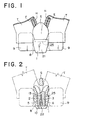
- the separable bottom stop assembly of the concealed slide fastener comprises three members, i.e., a box 1, a box pin 2, and a separable pin 3.
- the box 1, the box pin 2, and the separable pin 3 are respectively molded integrally by injection molding means or extrusion molding means using thermoplastic resin such as polyamide, polyacetals, polypropylene, and polybutylene terephthalate.
- the box pin 2 and the separable pin 3 are substantially in a shape of a prism and attached integrally to inner longitudinal edges of stringer tapes T, and connected continuously to fastener elements E attached to the side edges of the fastener stringer tapes T.
- the box 1 has an opening portion 4 at its front surface, and on its left and right sides, a box-pin-insertion hole 5 and a separable-pin-insertion hole 6.
- the box 1 is produced independently and is slidably fitted onto the box pin 2 attached to one of the stringer tapes T, thereby completing the separable bottom stop assembly.
- coiled fastener elements E made of thermoplastic synthetic fiber monofilament are sewn to a surface of the inner longitudinal edge of the fastener stringer tapes T folded in a U-shape, in such a manner that a meshing head portion H of each the fastener element E is disposed on an edge portion of the folded stringer tape T.
- the box pin 2 is attached by integral molding continuously to the fastener elements E.
- the separable pin 3 is also attached to an inner longitudinal edge of a folded stringer tape T similarly to the box pin 2.
- the fastener elements E may be ones of a zigzag type or separate type, and may be made of metal.
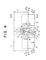
- the box pin 2 is connected continuously to an edge portion side, i.e., an inner edge of the folded stringer tape T so as to be in a shape of a key, in such a manner a U-shaped guide portion 8 is formed between the stringer tape T and the box pin 2 and is integrally molded with thermoplastic resin.
- another guide portion 8 is formed between the other stringer tape T and the separable pin 3 which is connected continuously to an edge portion side, i.e., an inner edge of the other folded stringer tape T, and is integrally molded with thermoplastic resin.
- the guide portions 8 formed on both the stringer tapes T guide flange portions 7 of the opening portion 4 formed in the front surface of the box 1.
- Support portions 9 are integrally molded on outsides of both of the horizontal U-shaped guide portions 8 with thermoplastic resin. As shown in FIG. 3, the guide portions 8 and the support portions 9 are formed at bottom end portions of the stringer tapes T. Also, the guide portions 8 and the support portions 9 are molded to be thin at their portions to which the box 1 is fitted, and the support portions 9 are molded to be thick at their portions outside the thin portions thereof. Sides of the support portions 9 facing the stringer tapes T extend to reach the front surfaces of the stringer tapes T while maintaining its thickness and are fixed to the stringer tapes T by fusing.
- the thick portions of the support portions 9 extend further than the box pin 2 and the separable pin 3 on the stringer tapes T, thereby reinforcing the end portions of the stringer tapes T so that the separable pin 3 can be smoothly fitted to and detached to and from the box 1.
- the box pin 2 has, at its inside lower end, a resilient portion 10 having resiliency and projecting in a shape of a hook.
- a recessed plunge portion 11 is provided at an inside of the resilient portion 10 to allow the resilient portion 10 to be resiliently deformed easily.
- the resilient portion 10 has at its lower end base portion a small projecting portion 12 to be pressed into the box-pin-insertion hole 5 provided to the box 1.
- a flat-face projecting portion 13 projecting inwardly is provided to the inner side surface of the box pin 2 above the resilient portion 10 at a distance from the resilient portion 10 corresponding to a size of an engaging portion 24 of a partitioning portion 22 provided to the box 1.
- the flat-face projecting portion 13 can be brought into abutment with the opposed separable pin 3.
- a recess portion 14 is formed above the flat-face projecting portion 13 with a difference in levels of the flat-face projecting portion 13 and the recess portion 14.
- An upper end of the box pin 2 is connected to the coiled fastener element E in such a manner hat a lower end portion of the fastener element E is recessed therein.
- a side wall 15 of the guide portion 8 connected to the inner side end of the box pin 2 is provided with an opening portion 16.
- the separable pin 3 is also formed in a shape of the prism and is continuously connected to the coil-shaped fastener elements E attached to an inner longitudinal edge of the other one of the folded stringer tapes.
- the separable pin 3 has at its inner side surface a slope portion 17 that is thinner toward its lower end, thereby allowing smooth insertion of the separable pin 3 into the box 1.
- the guide portion 8 connected continuously to the end of the inner side edge of the separable pin 3 has a notch portion 8 formed by notching an end of its side wall 15 parallel to the sloping portion 17 of the separable pin 3. Therefore, the guide portion 8 facilitates smooth movement of the box 1 along either of the flanges 7 formed on the box 1.
- the separable pin 3 is longer than the box pin 2 and has, at an upper portion of the inner side surface of the separable pin 3, a small hook portion 19 to be in abutment with and facing the recess portion 14 of the box pin 2 and meshed with the lowest one of the coiled fastener elements E.
- the separable pin 3 has, at an outer side surface thereof, a curved recessed face 20 so that the separable pin 3 can be smoothly inserted and set in a slider S and the box 1.
- the box 1 has, at a center of the front face thereof, the longitudinal opening portion 4, and at its left and right sides, the flanges 7.
- the box 1 further has, at a center of a back wall 21 of the box 1, the tongue-like partitioning portion 22, and on left and right sides of the partitioning portion 22, the box-pin-insertion hole 5 and the separable-pin-insertion hole 6.
- the separable-pin-insertion hole 6 has a bottom, while the box-pin-insertion hole 5 has a through hole 23 at its bottom for facilitating the molding of the partitioning portion 22, especially the engaging portion 24 projecting in a shape of a hook from an end of the partitioning portion 22 toward the box-pin-insertion hole 5.
- the engaging portion 24 is fitted between the resilient portion 10 and the flat-face projecting portion 13 of the box pin 2 to firmly fix the box pin 2 and the box 1.
- the partitioning portion 22 has a base portion sloping so as to be gradually thicker toward the bottom of the base portion. The partitioning portion 22 can be in abutment with the sloping portion 17 of the separable pin 3.
- the box 1 has at its upper surface a hollow portion 25 into which the slider S is fitted and which holds the slider S. Therefore, the slider S can be held in a stable state and moved smoothly in operation.
- the separable bottom stop assembly composed of the box 1, the box pin 2, and the separable pin 3 are assembled as described below.
- the slider S is inserted through the box pin 2.
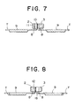
- the box 1 is mounted to the box pin 2 by inserting its flanges 7 into the guide portions 8 via the opening portion 4 and resiliently fitting the engaging portion 24 of the partitioning portion 22 between the resilient portion 10 and the flat-face projecting portion 12, thereby completing the assembling of the separable bottom stop assembly.
- the slider S After inserting the separable pin 3, which is attached to the stringer tape T sewn on an edge portion of the other side of the article, into the slider S and the separable-pin-insertion hole 6 of the box 1, the slider S is pushed up to mesh the opposite coiled fastener elements E attached to the left and right stringer tapes T with each other, thereby closing the fastener chain. The slider S is pushed down to detach the separable pin 3 from the box 1 and the slider S, thereby separating and opening the fastener chain.
- FIG. 11 shows an example of locking states of the box 1 and the box pin 2.
- FIG. 11 is identical with the first embodiment except that the box pin 2 in the shape of the prism has on its back surface a plurality of recess portions 36, and after the box pin 2 is inserted into the box-pin-insertion hole 5 in the box 1, a back wall 21 of the box 1 and the recess portion 36 of the box pin 2 are fused and fixed to each other by heating and pressing the back wall 21 of the box 1 from outside.
- the box pin 2 and the box 1 may be locked to each other in known , manners other than the above-mentioned embodiments.
- the separable bottom stop assembly of the concealed slide fastener according to the present invention having the above-described structure has the following effects.
- the guide portions 8 for guiding the flanges 7 of the box 1 having the opening portion 4 at the front face of the box 1 are respectively connected to the ends of the inner side edges of the prism-shaped box pin 2 and separable pin 3.
- the support portions 9 are connected continuously to the outsides of the guide portions 8, and the guide portions 8 and the support portions 9 are integrally molded to the ends of the stringer tapes T in such a manner that the box pin 2 can be inserted into and fixed to the box 1. Therefore, it is possible to easily reinforce the stringer tapes T and integrally mold the reinforced portion and the box pin 2 or the separable pin 3, thereby increasing a productivity of the separable bottom stop assembly.
- the separable bottom stop assembly is strong and not deformed, it is possible to easily achieve the separable bottom stop assembly which has desirable operability, is resistant to a use for a long time, and easy to handle.
- the box 1 can be attached afterward.
- the guide portions 8 and the support portions 9 connected continuously to the box pin 2 and the separable pin 3 are formed to be thin at their potions to which the box 1 is attached and to be thick at their portions outside the thin portions, and the thick portions of the support portions 9 extend to the front surfaces of the stringer tapes T. Therefore, it is possible to easily attach the box 1 to the box pin 2, and smoothly fit and detach the separable pin 3 to and from the box 1. Furthermore, since the support portions 9 are hardly peeled off or detached from the stringer tapes T, the separable bottom stop assembly is resistant to a use for a long time.
- the box 1 has a length larger than lengths of the guide portions 8 connected continuously to the box pin 2 and the separable pin 3 and the thin support portions 9 onto which the box 1 is disposed and has a length smaller than lengths of the box pin 2 and the separable pin 3. Therefore, the box 1 can be easily and reliably attached to the stringer tapes T, and the separable pin 3 is easy to handle.
- box pin 1 is inserted into the box-pin-insertion hole 5 formed in one side of the box 1 so that the box pin 1 can be fixed by locking or fusing.
- the box pin 1 is suitable for the separable bottom stop assembly with the box 1 attached afterward, and the box pin 2 and the box 1 can be easily fixed to each other by simple fixing means.
- the separable pin 3 has a sloping portion 17 at it inner side surface, and the guide portion 8 continuous to the ends of the inner side edge of the separable pin 3 has a notch portion 18 formed by notching the side wall end portion of the guide portion 8 so that the flange 7 of the box 1 can be inserted into the notch portion 18. Therefore, when the separable bottom stop assembly is used in a closed state, the separable pin 3 can be held in the box 1 in a remarkably stable state.
- the box 1 has at its center a tongue-like partitioning portion 22, and the tongue-like partitioning portion has a hook-shaped engaging portion 24 projecting from the end of the partitioning portion 22 toward the box-pin-insertion hole 5, and the box pin 2 has at its inner side surface a resilient portion 10 having resiliency so as to to be engaged with the engaging portion 24. Therefore, the box 1 can be remarkably smoothly and easily attached and fixed to the box pin 2.
- the box pin 2 has, at the base portion of the resilient portion 10 projecting from the box pin 2, a projecting portion 12 projecting inwardly to be in abutment with the partitioning portion 22.
- the box pin 2 also has, at the inner side surface of the box pin 1 above an end of the resilient portion 10, a flat-face projecting portion 13 at a distance corresponding to the size of the engaging portion 24 of the partitioning portion 22 from the resilient portion 10, so that that the flat-face projecting portion 13 can be in abutment with the separable pin 3. Therefore, the box 1 can be firmly fixed to the box pin 2 without tottering, and the strong separable bottom stop assembly can be obtained.
Landscapes
- Slide Fasteners (AREA)
- Connection Of Plates (AREA)
- Closures For Containers (AREA)
- Packages (AREA)
Claims (5)
- Ensemble de butée inférieure séparable pour fermeture à glissière du type masqué, composé d'un boítier (1), d'une cosse (2) de boítier et d'une cosse séparable (3) réalisés en résine thermoplastique, dans lequel des parties de guidage (8) horizontales en forme de U, non déformables, qui guident les rebords (7) du boítier (1), lesquels rebords comportent sur leur face avant une partie (4) formant une ouverture, sont respectivement reliées de façon continue aux extrémités des bords latéraux intérieurs de la cosse (2) de boítier et de la cosse séparable (3), toutes deux en forme de prisme, et des parties de support plates (9) sont reliées de façon continue aux côtés extérieurs des parties de guidage (8), les parties de guidage (8) et les parties de support (9), réalisées en résine thermoplastique étant moulées d'un seul tenant avec les extrémités inférieures des rubans (T) de bandes d'accrochage de fermeture de telle manière que la cosse (2) de boítier peut être insérée dans un trou (5) d'insertion de cosse de boítier du boítier (1), et être fixée à celui-ci, caractérisé en ce que
la cosse (2) de boítier peut être insérée dans le trou (5) d'insertion de cosse de boítier ménagé sur l'un des côtés du boítier (1), de telle manière que la cosse (2) de boítier puisse soit être verrouillée, soit être fondue superficiellement et fixée, et
le boítier (1) comporte en son centre une partie de séparation (22) analogue à une languette dotée d'une partie (24) d'accrochage en forme de crochet qui fait saillie depuis une extrémité de celle-ci en direction du trou (5) d'insertion de cosse de boítier, et la cosse (2) de boítier comporte sur sa surface du côté intérieur une partie résiliente (10) faisant saillie, dotée de résilience en vue d'être mise en prise avec la partie d'accrochage (24). - Ensemble de butée inférieure séparable pour fermeture à glissière du type masqué selon la revendication 1, caractérisé en ce que les parties de guidage (8) et les parties de support (9) sont réalisées de manière à être minces dans leurs parties où est disposé le boítier (1), et à être épaisses dans leurs parties situées à l'extérieur des parties minces, et en ce que les parties épaisses des parties de support (9) s'étendent jusqu'aux surfaces situées d'un seul côté des rubans (T) de bandes d'accrochage de fermeture et sont fixées à ces surfaces.
- Ensemble de butée inférieure séparable pour fermeture à glissière du type masqué selon la revendication 1, caractérisé en ce que le boítier (1) a une longueur supérieure aux longueurs des parties de guidage (8) et aux longueurs des parties minces des parties de support (9) là où est disposé le boítier (1) et inférieure aux longueurs de la cosse (2) de boítier et de la cosse séparable (3).
- Ensemble de butée inférieure séparable pour fermeture à glissière du type masqué selon la revendication 1, caractérisé en ce que la cosse séparable (3) comporte une surface latérale intérieure formant une pente, et en ce que la partie de guidage (8) horizontale en forme de U qui est en continuité avec les extrémités du bord latéral intérieur de la cosse séparable (3) comporte une partie (18) formant une encoche réalisée en faisant une encoche sur la partie d'extrémité d'une paroi latérale (15) de la partie de guidage (8) de façon telle que le rebord (7) du boítier (1) peut être inséré dans la partie formant une encoche (18).
- Ensemble de butée inférieure séparable pour fermeture à glissière du type masqué selon la revendication 1, caractérisé en ce que la cosse (2) de boítier comporte, sur la portion de base de la partie résiliente (10), une partie en saillie (12) qui fait saillie vers l'intérieur de manière à être en butée contre la partie de séparation (22) et, sur sa surface latérale intérieure, au-dessus de la partie résiliente (10), une partie en saillie (13) dotée d'une face plate, à une distance correspondant à la longueur de la partie d'accrochage (24) de la partie de séparation (22) depuis la partie résiliente (10), de telle manière que la partie en saillie (13) peut être en butée avec la cosse séparable (13).
Applications Claiming Priority (3)
| Application Number | Priority Date | Filing Date | Title |
|---|---|---|---|
| JP32800597A JP3589440B2 (ja) | 1997-11-28 | 1997-11-28 | 隠しスライドファスナーの開離嵌挿具 |
| JP32800597 | 1997-11-28 | ||
| JP328005/97 | 1997-11-28 |
Publications (3)
| Publication Number | Publication Date |
|---|---|
| EP0919152A2 EP0919152A2 (fr) | 1999-06-02 |
| EP0919152A3 EP0919152A3 (fr) | 1999-09-29 |
| EP0919152B1 true EP0919152B1 (fr) | 2004-06-16 |
Family
ID=18205453
Family Applications (1)
| Application Number | Title | Priority Date | Filing Date |
|---|---|---|---|
| EP98121042A Expired - Lifetime EP0919152B1 (fr) | 1997-11-28 | 1998-11-05 | Butée d'extrémité inférieure séparable pour fermeture à glissière du type masqué |
Country Status (10)
| Country | Link |
|---|---|
| US (1) | US6112376A (fr) |
| EP (1) | EP0919152B1 (fr) |
| JP (1) | JP3589440B2 (fr) |
| KR (1) | KR100298803B1 (fr) |
| CN (1) | CN1177550C (fr) |
| BR (1) | BR9805511A (fr) |
| DE (1) | DE69824526T2 (fr) |
| ES (1) | ES2219828T3 (fr) |
| ID (1) | ID21379A (fr) |
| TW (1) | TW407468U (fr) |
Families Citing this family (25)
| Publication number | Priority date | Publication date | Assignee | Title |
|---|---|---|---|---|
| JP3621006B2 (ja) * | 1999-09-30 | 2005-02-16 | Ykk株式会社 | 開離嵌挿具付スライドファスナーの開離嵌挿具およびスライダー |
| JP3621040B2 (ja) * | 2000-10-31 | 2005-02-16 | Ykk株式会社 | スライドファスナーの逆開き開離嵌挿具 |
| US6618911B1 (en) * | 2000-11-28 | 2003-09-16 | Roger C. Y. Chung | Bottom open-end type invisible zipper with a movable bottom-end piece |
| US6502285B2 (en) | 2001-03-16 | 2003-01-07 | Alice Mary Kiely | Immobilized and aligned closure systems |
| JP3733327B2 (ja) * | 2001-12-20 | 2006-01-11 | Ykk株式会社 | 隠しスライドファスナーの開離嵌挿具 |
| JP3736755B2 (ja) * | 2002-03-26 | 2006-01-18 | Ykk株式会社 | スライドファスナー用開離嵌挿具 |
| JP3909491B2 (ja) * | 2002-09-20 | 2007-04-25 | Ykk株式会社 | 隠しスライドファスナー用スライダー |
| US6775885B1 (en) * | 2003-05-14 | 2004-08-17 | Lien-Chou Wang | Two way open-end zipper |
| US7643632B2 (en) * | 2004-02-25 | 2010-01-05 | Ternarylogic Llc | Ternary and multi-value digital signal scramblers, descramblers and sequence generators |
| USD510891S1 (en) * | 2004-11-16 | 2005-10-25 | Unitech Zipper And Machinery Co., Ltd. | Stop device for a two-way invisible zipper |
| JP4238229B2 (ja) * | 2005-04-20 | 2009-03-18 | Ykk株式会社 | スライドファスナー用上止 |
| JP4651634B2 (ja) * | 2007-03-15 | 2011-03-16 | Ykk株式会社 | 隠しスライドファスナー |
| ES2537966T3 (es) * | 2008-10-06 | 2015-06-16 | Ykk Corporation | Cierre de cremallera |
| US20100299886A1 (en) * | 2009-05-27 | 2010-12-02 | Eric Fodge | Zipper with removable slider |
| US20120167354A1 (en) * | 2009-09-11 | 2012-07-05 | Ykk Corporation | Reverse Opening Slide Fastener |
| KR101325441B1 (ko) * | 2009-11-30 | 2013-11-04 | 와이케이케이 가부시끼가이샤 | 액밀 슬라이드 파스너 및 그 제조 방법 |
| US8782859B2 (en) * | 2010-04-28 | 2014-07-22 | Ykk Corporation | Concealed slide fastener |
| KR100995740B1 (ko) * | 2010-04-30 | 2010-11-19 | 정태영 | 지퍼용 핀박스 기능을 포함하는 분리형 슬라이더 조립구조 |
| JP5414895B2 (ja) * | 2010-06-23 | 2014-02-12 | Ykk株式会社 | スライドファスナー |
| CN105307533B (zh) * | 2013-05-29 | 2018-06-26 | Ykk株式会社 | 带有可分离式嵌插件的拉链及射出成形用模具 |
| TWI475968B (zh) * | 2013-07-29 | 2015-03-11 | Fabrication and setting method of nylon double - layer tooth zipper | |
| TWI631916B (zh) * | 2017-05-24 | 2018-08-11 | 中傳企業股份有限公司 | 拉鍊頭組合結構及其梢狀組件 |
| US10869526B2 (en) | 2019-01-04 | 2020-12-22 | Target Brands, Inc. | Slide closure with stabilizing fins and associated garment |
| US11805864B1 (en) * | 2022-05-09 | 2023-11-07 | Kcc Zipper Co., Ltd. | Lower stop device of an anti-pinch zipper and its assembly structure |
| CN116807138B (zh) * | 2023-08-03 | 2026-01-02 | 浙江伟星实业发展股份有限公司 | 一种组合下止、拉链和拉链制品 |
Family Cites Families (11)
| Publication number | Priority date | Publication date | Assignee | Title |
|---|---|---|---|---|
| CH295031A (de) * | 1951-08-23 | 1953-12-15 | Hug Jacques | Vollständig trennbarer verdeckter Reissverschluss. |
| NL243487A (fr) * | 1958-10-23 | |||
| US3046627A (en) * | 1960-05-09 | 1962-07-31 | Louis H Morin | Separator for invisible separable fastener stringers |
| US3224061A (en) * | 1964-09-17 | 1965-12-21 | Scovill Manufacturing Co | Terminal member for plastic filament zippers |
| FR2082871A5 (fr) * | 1970-03-31 | 1971-12-10 | Fflb | |
| JPS5758969Y2 (fr) * | 1978-04-19 | 1982-12-16 | ||
| JPS5950313U (ja) * | 1982-09-27 | 1984-04-03 | ワイケイケイ株式会社 | 開離嵌插具付きスライドフアスナ− |
| JPH02128702A (ja) * | 1988-11-08 | 1990-05-17 | Yoshida Kogyo Kk <Ykk> | 開離嵌挿具付きスライドファスナー |
| JP2774218B2 (ja) * | 1992-07-31 | 1998-07-09 | ワイケイケイ株式会社 | 隠しスライドファスナーの開離嵌挿具および開離嵌挿方法 |
| JPH0838219A (ja) * | 1994-07-29 | 1996-02-13 | Ykk Kk | スライドファスナーの開離嵌挿具 |
| JP3285453B2 (ja) * | 1994-09-30 | 2002-05-27 | ワイケイケイ株式会社 | スライドファスナー用合成樹脂製開離嵌挿具 |
-
1997
- 1997-11-28 JP JP32800597A patent/JP3589440B2/ja not_active Expired - Fee Related
-
1998
- 1998-11-05 DE DE69824526T patent/DE69824526T2/de not_active Expired - Fee Related
- 1998-11-05 ES ES98121042T patent/ES2219828T3/es not_active Expired - Lifetime
- 1998-11-05 EP EP98121042A patent/EP0919152B1/fr not_active Expired - Lifetime
- 1998-11-19 TW TW088220106U patent/TW407468U/zh not_active IP Right Cessation
- 1998-11-25 US US09/199,299 patent/US6112376A/en not_active Expired - Fee Related
- 1998-11-27 KR KR1019980051229A patent/KR100298803B1/ko not_active Expired - Lifetime
- 1998-11-27 ID IDP981549A patent/ID21379A/id unknown
- 1998-11-27 BR BR9805511-9A patent/BR9805511A/pt not_active IP Right Cessation
- 1998-11-30 CN CNB981229646A patent/CN1177550C/zh not_active Expired - Lifetime
Also Published As
| Publication number | Publication date |
|---|---|
| JP3589440B2 (ja) | 2004-11-17 |
| DE69824526D1 (de) | 2004-07-22 |
| EP0919152A3 (fr) | 1999-09-29 |
| KR100298803B1 (ko) | 2001-10-29 |
| US6112376A (en) | 2000-09-05 |
| KR19990045638A (ko) | 1999-06-25 |
| ES2219828T3 (es) | 2004-12-01 |
| JPH11155616A (ja) | 1999-06-15 |
| CN1228948A (zh) | 1999-09-22 |
| CN1177550C (zh) | 2004-12-01 |
| BR9805511A (pt) | 1999-11-16 |
| HK1021877A1 (en) | 2000-07-14 |
| TW407468U (en) | 2000-10-01 |
| EP0919152A2 (fr) | 1999-06-02 |
| ID21379A (id) | 1999-06-03 |
| DE69824526T2 (de) | 2005-08-18 |
Similar Documents
| Publication | Publication Date | Title |
|---|---|---|
| US6112376A (en) | Separable bottom stop assembly of concealed slide fastener | |
| EP0804886B1 (fr) | Curseur à verrouillage automatique et appareillage de moulage du couvercle du curseur | |
| EP0992201B1 (fr) | Butée d'arrêt inférieure séparable pour fermeture à glissière | |
| EP1938706B1 (fr) | Fermeture à glissière avec butée d'arrêt supérieure | |
| KR100361266B1 (ko) | 분리식 저부 정지 조립체를 가진 슬라이드 파스너 | |
| EP0917837B1 (fr) | Butée d'arrêt inférieure séparable pour fermeture à glissière | |
| EP1321062B1 (fr) | Butée d'extrémité inférieure séparable pour fermetures à glissière de type masqué | |
| US7340806B2 (en) | Opener for slide fastener | |
| CA1282941C (fr) | Fermeture a glissiere etanche aux fluides | |
| EP0704177B1 (fr) | Butée d'arrêt inférieure séparable en résine synthétique pour fermeture à glissière | |
| JPH01313001A (ja) | 開離嵌挿具付防水スライドファスナー | |
| US7669296B2 (en) | Slide fastener | |
| KR20050028795A (ko) | 슬라이드 파스너의 상부 정지구 | |
| US5913481A (en) | Separable slide fastener | |
| EP1348351B1 (fr) | Butée d'arret inférieure séparable pour fermeture à glissière | |
| EP0383603A1 (fr) | Fermeture à glissière | |
| JP3580395B2 (ja) | 開離型隠しスライドファスナー | |
| HK1003162B (en) | Auto-lock slide fastener slider and apparatus for molding slider cover | |
| HK1021877B (en) | Separable bottom stop assembly of concealed slide fastenre | |
| HK1096266B (zh) | 拉链 |
Legal Events
| Date | Code | Title | Description |
|---|---|---|---|
| PUAI | Public reference made under article 153(3) epc to a published international application that has entered the european phase |
Free format text: ORIGINAL CODE: 0009012 |
|
| AK | Designated contracting states |
Kind code of ref document: A2 Designated state(s): DE ES FR GB IT |
|
| AX | Request for extension of the european patent |
Free format text: AL;LT;LV;MK;RO;SI |
|
| PUAL | Search report despatched |
Free format text: ORIGINAL CODE: 0009013 |
|
| AK | Designated contracting states |
Kind code of ref document: A3 Designated state(s): AT BE CH CY DE DK ES FI FR GB GR IE IT LI LU MC NL PT SE |
|
| AX | Request for extension of the european patent |
Free format text: AL;LT;LV;MK;RO;SI |
|
| 17P | Request for examination filed |
Effective date: 20000323 |
|
| AKX | Designation fees paid |
Free format text: DE ES FR GB IT |
|
| 17Q | First examination report despatched |
Effective date: 20011120 |
|
| GRAP | Despatch of communication of intention to grant a patent |
Free format text: ORIGINAL CODE: EPIDOSNIGR1 |
|
| GRAS | Grant fee paid |
Free format text: ORIGINAL CODE: EPIDOSNIGR3 |
|
| GRAA | (expected) grant |
Free format text: ORIGINAL CODE: 0009210 |
|
| AK | Designated contracting states |
Kind code of ref document: B1 Designated state(s): DE ES FR GB IT |
|
| REG | Reference to a national code |
Ref country code: GB Ref legal event code: FG4D |
|
| REF | Corresponds to: |
Ref document number: 69824526 Country of ref document: DE Date of ref document: 20040722 Kind code of ref document: P |
|
| REG | Reference to a national code |
Ref country code: ES Ref legal event code: FG2A Ref document number: 2219828 Country of ref document: ES Kind code of ref document: T3 |
|
| ET | Fr: translation filed | ||
| PLBE | No opposition filed within time limit |
Free format text: ORIGINAL CODE: 0009261 |
|
| STAA | Information on the status of an ep patent application or granted ep patent |
Free format text: STATUS: NO OPPOSITION FILED WITHIN TIME LIMIT |
|
| 26N | No opposition filed |
Effective date: 20050317 |
|
| PGFP | Annual fee paid to national office [announced via postgrant information from national office to epo] |
Ref country code: GB Payment date: 20051102 Year of fee payment: 8 |
|
| PGFP | Annual fee paid to national office [announced via postgrant information from national office to epo] |
Ref country code: DE Payment date: 20051103 Year of fee payment: 8 |
|
| PGFP | Annual fee paid to national office [announced via postgrant information from national office to epo] |
Ref country code: FR Payment date: 20051108 Year of fee payment: 8 |
|
| PGFP | Annual fee paid to national office [announced via postgrant information from national office to epo] |
Ref country code: ES Payment date: 20051219 Year of fee payment: 8 |
|
| PGFP | Annual fee paid to national office [announced via postgrant information from national office to epo] |
Ref country code: IT Payment date: 20061130 Year of fee payment: 9 |
|
| PG25 | Lapsed in a contracting state [announced via postgrant information from national office to epo] |
Ref country code: DE Free format text: LAPSE BECAUSE OF NON-PAYMENT OF DUE FEES Effective date: 20070601 |
|
| GBPC | Gb: european patent ceased through non-payment of renewal fee |
Effective date: 20061105 |
|
| REG | Reference to a national code |
Ref country code: FR Ref legal event code: ST Effective date: 20070731 |
|
| PG25 | Lapsed in a contracting state [announced via postgrant information from national office to epo] |
Ref country code: GB Free format text: LAPSE BECAUSE OF NON-PAYMENT OF DUE FEES Effective date: 20061105 |
|
| REG | Reference to a national code |
Ref country code: ES Ref legal event code: FD2A Effective date: 20061106 |
|
| PG25 | Lapsed in a contracting state [announced via postgrant information from national office to epo] |
Ref country code: FR Free format text: LAPSE BECAUSE OF NON-PAYMENT OF DUE FEES Effective date: 20061130 Ref country code: ES Free format text: LAPSE BECAUSE OF NON-PAYMENT OF DUE FEES Effective date: 20061106 |
|
| PG25 | Lapsed in a contracting state [announced via postgrant information from national office to epo] |
Ref country code: IT Free format text: LAPSE BECAUSE OF NON-PAYMENT OF DUE FEES Effective date: 20071105 |