EP0919361A2 - Verfahren zur Herstellung von einem Gegenstand mit eingebettetem Rand - Google Patents
Verfahren zur Herstellung von einem Gegenstand mit eingebettetem Rand Download PDFInfo
- Publication number
- EP0919361A2 EP0919361A2 EP98122495A EP98122495A EP0919361A2 EP 0919361 A2 EP0919361 A2 EP 0919361A2 EP 98122495 A EP98122495 A EP 98122495A EP 98122495 A EP98122495 A EP 98122495A EP 0919361 A2 EP0919361 A2 EP 0919361A2
- Authority
- EP
- European Patent Office
- Prior art keywords
- peripheral
- encapsulation
- performance
- bisecting plane
- peripheral encapsulation
- Prior art date
- Legal status (The legal status is an assumption and is not a legal conclusion. Google has not performed a legal analysis and makes no representation as to the accuracy of the status listed.)
- Granted
Links
- 238000004519 manufacturing process Methods 0.000 title claims description 6
- 230000002093 peripheral effect Effects 0.000 claims abstract description 88
- 238000005538 encapsulation Methods 0.000 claims abstract description 64
- 239000000463 material Substances 0.000 claims abstract description 10
- 238000000465 moulding Methods 0.000 claims abstract description 6
- 238000000034 method Methods 0.000 claims description 29
- 238000001816 cooling Methods 0.000 claims description 5
- 239000011521 glass Substances 0.000 description 13
- 238000002347 injection Methods 0.000 description 12
- 239000007924 injection Substances 0.000 description 12
- 229910000831 Steel Inorganic materials 0.000 description 4
- 229920001577 copolymer Polymers 0.000 description 4
- 239000010959 steel Substances 0.000 description 4
- 230000002411 adverse Effects 0.000 description 3
- 238000001746 injection moulding Methods 0.000 description 3
- 239000000919 ceramic Substances 0.000 description 1
- 238000010276 construction Methods 0.000 description 1
- 230000006866 deterioration Effects 0.000 description 1
- 230000000694 effects Effects 0.000 description 1
- 230000000750 progressive effect Effects 0.000 description 1
- 230000003252 repetitive effect Effects 0.000 description 1
Images

Classifications
-
- B—PERFORMING OPERATIONS; TRANSPORTING
- B29—WORKING OF PLASTICS; WORKING OF SUBSTANCES IN A PLASTIC STATE IN GENERAL
- B29C—SHAPING OR JOINING OF PLASTICS; SHAPING OF MATERIAL IN A PLASTIC STATE, NOT OTHERWISE PROVIDED FOR; AFTER-TREATMENT OF THE SHAPED PRODUCTS, e.g. REPAIRING
- B29C65/00—Joining or sealing of preformed parts, e.g. welding of plastics materials; Apparatus therefor
- B29C65/66—Joining or sealing of preformed parts, e.g. welding of plastics materials; Apparatus therefor by liberation of internal stresses, e.g. shrinking of one of the parts to be joined
- B29C65/665—Joining or sealing of preformed parts, e.g. welding of plastics materials; Apparatus therefor by liberation of internal stresses, e.g. shrinking of one of the parts to be joined using shrinking during cooling
-
- B—PERFORMING OPERATIONS; TRANSPORTING
- B29—WORKING OF PLASTICS; WORKING OF SUBSTANCES IN A PLASTIC STATE IN GENERAL
- B29C—SHAPING OR JOINING OF PLASTICS; SHAPING OF MATERIAL IN A PLASTIC STATE, NOT OTHERWISE PROVIDED FOR; AFTER-TREATMENT OF THE SHAPED PRODUCTS, e.g. REPAIRING
- B29C63/00—Lining or sheathing, i.e. applying preformed layers or sheathings of plastics; Apparatus therefor
- B29C63/0026—Lining or sheathing, i.e. applying preformed layers or sheathings of plastics; Apparatus therefor an edge face with strip material, e.g. a panel edge
-
- B—PERFORMING OPERATIONS; TRANSPORTING
- B29—WORKING OF PLASTICS; WORKING OF SUBSTANCES IN A PLASTIC STATE IN GENERAL
- B29C—SHAPING OR JOINING OF PLASTICS; SHAPING OF MATERIAL IN A PLASTIC STATE, NOT OTHERWISE PROVIDED FOR; AFTER-TREATMENT OF THE SHAPED PRODUCTS, e.g. REPAIRING
- B29C66/00—General aspects of processes or apparatus for joining preformed parts
- B29C66/01—General aspects dealing with the joint area or with the area to be joined
- B29C66/03—After-treatments in the joint area
- B29C66/034—Thermal after-treatments
- B29C66/0342—Cooling, e.g. transporting through welding and cooling zone
-
- B—PERFORMING OPERATIONS; TRANSPORTING
- B29—WORKING OF PLASTICS; WORKING OF SUBSTANCES IN A PLASTIC STATE IN GENERAL
- B29K—INDEXING SCHEME ASSOCIATED WITH SUBCLASSES B29B, B29C OR B29D, RELATING TO MOULDING MATERIALS OR TO MATERIALS FOR MOULDS, REINFORCEMENTS, FILLERS OR PREFORMED PARTS, e.g. INSERTS
- B29K2709/00—Use of inorganic materials not provided for in groups B29K2703/00 - B29K2707/00, for preformed parts, e.g. for inserts
- B29K2709/08—Glass
-
- Y—GENERAL TAGGING OF NEW TECHNOLOGICAL DEVELOPMENTS; GENERAL TAGGING OF CROSS-SECTIONAL TECHNOLOGIES SPANNING OVER SEVERAL SECTIONS OF THE IPC; TECHNICAL SUBJECTS COVERED BY FORMER USPC CROSS-REFERENCE ART COLLECTIONS [XRACs] AND DIGESTS
- Y10—TECHNICAL SUBJECTS COVERED BY FORMER USPC
- Y10S—TECHNICAL SUBJECTS COVERED BY FORMER USPC CROSS-REFERENCE ART COLLECTIONS [XRACs] AND DIGESTS
- Y10S264/00—Plastic and nonmetallic article shaping or treating: processes
- Y10S264/71—Processes of shaping by shrinking
Definitions
- Such a support frame includes an integrally formed body of uniform cross section defining a generally inwardly opening channel as disclosed in, for example, U.S. Patent No. 4,914,888 in the name of Laurence B. Hanson which granted on April 10, 1990. Screws are inserted through an opening in one side wall of the channel and are threaded into an opening in a second side wall of the channel to draw the two side walls into gripping contact with the glass panel, thus providing a relatively unitized and rigid supporting frame.
- Typical also of a frame of this type is such as that disclosed in U.S. Patent No. 3,363,390 in the name of Jameson Crane granted on January 16, 1968.
- the frame member in this case is extruded and is folded around a peripheral edge of an associated panel with a screw uniting a single corner of the frame.
- Such shelves are manufactured in an injection mold of the type disclosed in pending application Serial No. 08/303,200 filed on September 8, 1994 in the names of Max Meier et al.
- a glass plate or panel has its peripheral edge located in a peripheral cavity into which highly pressurized plastic material is injected and, upon subsequent cooling, the edge of the panel is bounded by a polymeric frame or encapsulation which, since intended for use as a refrigerator shelf, has also integrally unitized thereto opposite metallic shelf brackets.
- a cook top is manufactured similarly in pending application Serial No. 08/890,651 filed on July 9, 1997.
- a primary object of the present invention is to provide a novel and unobvious method of manufacturing a peripherally encapsulated unit, such as a refrigerator shelf, a range oven door, a microwave oven door, a cook top, a hob top, a "touch" control panel or the like.
- a peripherally encapsulated unit such as a refrigerator shelf, a range oven door, a microwave oven door, a cook top, a hob top, a "touch" control panel or the like.
- an injection mold is provided which defines a peripheral cavity in which can be injection molded a frame or encapsulation having an inwardly opening preferably continuous channel.
- the cavity is at least partially opened, and a panel, such as a Ceran® or glass panel, is moved into the mold into alignment with a channel of the still hot injected frame or encapsulation.
- a peripheral edge of the panel is maintained in alignment with the channel of the encapsulation as the latter cools.
- the cooling of the encapsulation or injection molded frame results in the shrinkage thereof which brings the channel into progressive intimate embracing relationship to a peripheral edge of the glass or Ceran® panel eventually resulting in a unitized peripherally encapsulated unit which can, for example, constitute a cook top, a door for a range oven, a "touch" control panel for an oven, range or the like wherein the Ceran®/glass panel includes so-called "touch” circuitry, or similar structures.
- One major advantage of the aforesaid method is that during the molding thereof, the panel need not be inserted into the mold and subject to heat and pressure which is highly undesirable, particularly in such applications as "touch" control panel circuitry, the electronics of which can be adversely effected under relatively high molding temperatures.
- the material from which the "insert” member might be made it is subject to less pressure and temperature than heretofore noted and only the peripheral edge thereof is briefly subject to elevated temperature as the encapsulation/frame cools and shrinks into conformity with the periphery of the insert.
- relatively close tolerances can be maintained at high production output and at minimum deterioration, as might not otherwise occur under elevated injection molding temperatures and pressures.
- a mold 10 is illustrated in the fully closed position thereof in Figure 1 of the drawings, and includes an upper mold body or cavity steel 11, a lower mold body or cavity steel 12, and an inner central mold or core steel 13 beneath which and spaced therefrom is a vacuum cup mounting member or plate 14 which carries a plurality of vacuum cups 15 connected conventionally through valved lines (not shown) to a source of negative air pressure (also not shown).
- the upper mold body 11 is of a generally open polygonal frame-like configuration defined by an upper surface 21, a lower surface 22, an inner peripheral surface 23, a medial annular surface 24 and three cavity-defining surfaces 25, 26 and 27 with the surfaces 25, 26 and 26, 27 merging at rounded radius surfaces (unnumbered).
- the cavity-defining surfaces 25, 27 are substantially in parallel relationship to each other, and each is substantially normal to the cavity-defining surface 26.
- the lower mold body 12 is also of a generally frame-like configuration and includes an upper cavity-defining surface 32, a lower surface 33 and an inboardmost peripheral surface 34.
- the lower mold body 12 is of a multi-part movable construction and can be moved in a conventional manner front the closed position shown in Figure 1 in which the surfaces 25 through 27 and 32 define a closed frame-like mold cavity 35 and an open position ( Figure 2) in which the various lower mold body portions or segments 12 are retracted to an open position at which the inboardmost peripheral surface 34 of the lower mold body 12 is outboard of the cavity-defining surface 25 of the mold cavity 35 of the upper mold body 11.
- the inner mold body or core steel 13 includes an uppermost surface 41, a lowermost surface 42 and three outer peripheral surfaces 43, 44 and 45, the latter of which is joined to the two former surfaces by respective annular surfaces 46 and 47.
- the surfaces 44, 45, 46 and a portion of the surface 47 essentially define the cross-section configuration of the closed mold cavity 35 and specifically define the innermost peripheral configuration thereof in the manner clearly illustrated in Figure 1.
- the inner mold body 13 is also a segmented mold body and segments or portions thereof can be shifted inward to an open position ( Figure 2) for purposes to be hereinafter described.
- Conventional injectors I such as the four conventional injectors 60 shown in Figure 5 of application Serial No. 08/303,200, are provided to inject hot polymeric/copolymeric synthetic plastic material under pressure into the mold cavity 35 in the closed position thereof ( Figure 1), preferably at each of the four corners (not shown) of the mold cavity 35 to form an opened frame, frame member or encapsulation F under heat and pressure during the conventional molding cycle of an associated injection molding machine.
- a generally polygonal/rectangular piece of glass, Ceran® panel or like material G is located in accurate centered relationship to the overall mold 10 and particularly relative to the mold cavity 35.
- the panel, insert or inner member G includes a peripheral edge P1 which is accurately sized to correspond in shape, size, configuration and overall dimensions to the shape, size, configuration and overall dimensions of the outermost peripheral surface 44 of the inner mold body 13 when closed ( Figure 1), but is ever so slightly smaller in each of its shape, size and configuration and overall dimensions.
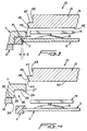
- An imaginary alignment line L shown in Figure 2 reflects the close tolerances between the peripheral edge P1 of the inner member G and the lower peripheral surface LPS of the frame or encapsulate F which, upon upward movement of the inner mold body 13 and the vacuum cup mounting member 14 in the manner shown in Figure 3, brings the member or panel G to the position shown in Figure 3 at which its peripheral surface P1 is in alignment with an opposing surface (unnumbered) of the encapsulate F formed by the surface 45 of the inner mold body 13 and in part defining therewith a peripherally inwardly opening continuous channel, groove or slot C.
- a peripheral space S ( Figure 3) exists between the innermost bottom peripheral surface (unnumbered) of the continuous channel C and the peripheral edge P1 of the inner member G at and shortly after the time that the mold 10 has been opened and while the encapsulation F remains hot.
- the material thereof shrinks and eventually the space or gap S is closed ( Figure 4) which allows the encapsulation F to shrink over, clamp to and bond with the entire peripheral/polygonal edge portion (unnumbered) of the inner member G forming a peripherally encapsulated unit U ( Figure 4) which might be, for example, a door for an oven, a door for a microwave oven, an electronic "touch" control panel or a cook top, such as the ceramic cook top and/or hob top disclosed in U.S.
- the Ceran®, glass or like panel G need not be separately post attached to the frame F after cooling and/or mold ejection, nor is the panel G adversely effected by being held in a mold body while the periphery thereof is encapsulated by hot injection molded polymeric/copolymeric material which could adversely effect circuitry of "touch" control panels, as occurs with conventional practices earlier herein mentioned.
- the peripherally encapsulated unit U is, therefore, capable of rapid and repetitive low cost manufacture absent disadvantages of prior art post assembly or in-mold injection assembly, as is presently conventionally practiced.
Landscapes
- Engineering & Computer Science (AREA)
- Mechanical Engineering (AREA)
- Manufacturing & Machinery (AREA)
- Physics & Mathematics (AREA)
- Thermal Sciences (AREA)
- Moulds For Moulding Plastics Or The Like (AREA)
- Injection Moulding Of Plastics Or The Like (AREA)
- Casting Or Compression Moulding Of Plastics Or The Like (AREA)
Applications Claiming Priority (2)
| Application Number | Priority Date | Filing Date | Title |
|---|---|---|---|
| US980775 | 1997-12-01 | ||
| US08/980,775 US6210618B1 (en) | 1997-12-01 | 1997-12-01 | Method of manufacturing a peripherally encapsulating unit |
Publications (3)
| Publication Number | Publication Date |
|---|---|
| EP0919361A2 true EP0919361A2 (de) | 1999-06-02 |
| EP0919361A3 EP0919361A3 (de) | 1999-07-14 |
| EP0919361B1 EP0919361B1 (de) | 2003-02-05 |
Family
ID=25527840
Family Applications (1)
| Application Number | Title | Priority Date | Filing Date |
|---|---|---|---|
| EP98122495A Expired - Lifetime EP0919361B1 (de) | 1997-12-01 | 1998-11-27 | Verfahren zur Herstellung von einem Gegenstand mit eingebettetem Rand |
Country Status (5)
| Country | Link |
|---|---|
| US (1) | US6210618B1 (de) |
| EP (1) | EP0919361B1 (de) |
| CA (1) | CA2254660C (de) |
| DE (1) | DE69811184T2 (de) |
| ES (1) | ES2192734T3 (de) |
Cited By (4)
| Publication number | Priority date | Publication date | Assignee | Title |
|---|---|---|---|---|
| US7429344B2 (en) | 2001-07-31 | 2008-09-30 | Fujifilm Corporation | Method of mounting a resin-molded member |
| EP2011399A1 (de) | 2007-07-02 | 2009-01-07 | Electrolux Home Products Corporation N.V. | Ofentür mit Türrahmen und Türblatt |
| EP1585404A4 (de) * | 2003-01-24 | 2009-12-09 | Ssw Holding Co Inc | Heissverprägtes regal |
| FR2949377A1 (fr) * | 2009-09-01 | 2011-03-04 | Saint Gobain | Procede et installation de fabrication d'une etagere, en particulier pour des installations refrigerees |
Families Citing this family (9)
| Publication number | Priority date | Publication date | Assignee | Title |
|---|---|---|---|---|
| US6045101A (en) * | 1998-01-30 | 2000-04-04 | Waltec Plastics Inc. | Article support |
| US6174482B1 (en) | 1998-10-26 | 2001-01-16 | Gemtron Corporation | Method of manufacturing an interlocked, “flush-to-front,” injection molded border and glass sheet |
| FR2822664B1 (fr) * | 2001-03-27 | 2004-07-02 | Saint Gobain | Etagere pour le support d'articles, en particulier dans des installations refrigerees |
| US20050280341A1 (en) * | 2001-03-27 | 2005-12-22 | Saint-Gobain Glass France | Shelf and frame for supporting a container, particularly in refrigerated installations |
| US6773652B2 (en) * | 2002-10-02 | 2004-08-10 | Elster Electricity, Llc | Process for the manufacture of a cover system for an electrical-energy meter |
| US8231191B2 (en) * | 2007-02-16 | 2012-07-31 | Saint-Gobain Glass France | Shelf for supporting articles, particularly in refrigerated installations |
| FR2929811B3 (fr) * | 2008-04-09 | 2010-08-27 | Saint Gobain | Etagere, en particulier pour des installations refrigerees |
| CN103453562B (zh) * | 2013-09-02 | 2016-06-29 | 诺孚电器股份有限公司 | 一种灶台面板及安装灶台面板的夹具 |
| US9945601B1 (en) | 2016-10-14 | 2018-04-17 | Whirlpool Corporation | Refrigerator shelf and method for producing the shelf |
Family Cites Families (31)
| Publication number | Priority date | Publication date | Assignee | Title |
|---|---|---|---|---|
| US1981334A (en) | 1930-07-17 | 1934-11-20 | Colt S Mfg Co | Article of manufacture |
| FR875506A (fr) | 1940-10-02 | 1942-09-25 | Westfalische Metall Ind Aktien | Procédés de fixation des corps de forme et de composition quelconques dans des enchâssements en matière moulée |
| US3207830A (en) * | 1959-08-24 | 1965-09-21 | American Can Co | Method of making a reinforced container closure |
| US3232615A (en) * | 1961-04-18 | 1966-02-01 | Albany Billiard Ball Company | Bowling pin with wear-resistant insert and interlocking retainer |
| US3399018A (en) * | 1963-10-02 | 1968-08-27 | Foster Grant Co Inc | Rolled eyeglass lens rim construction |
| US3363390A (en) | 1966-04-25 | 1968-01-16 | Crane Plastics Inc | Extruded plastic panel-framing strip having integral rigid body section and resiliently flexible panel-gripping flanges |
| US3470604A (en) * | 1966-07-01 | 1969-10-07 | American Hospital Supply Corp | Method of making a hypodermic needle |
| GB1570816A (en) | 1977-03-25 | 1980-07-09 | Devillers Jean Pierre | Method of assembling castings and the resulting products |
| GB2169544B (en) | 1984-06-25 | 1988-08-24 | Caterpiller Inc | Method of forming a windowed unitary panel |
| FR2572987B1 (fr) | 1984-09-21 | 1987-01-02 | Pont A Mousson | Procede et dispositif de surmoulage d'un entourage de dimensions precises sur le pourtour d'une piece plane ou galbee a tolerances dimensionnelles |
| US4830804A (en) * | 1987-01-02 | 1989-05-16 | Libbey-Owens-Ford Co. | Method of molding a window assembly |
| US4870736A (en) | 1988-01-19 | 1989-10-03 | Chris Kaye Plastics Corp. | Method of assembling a molded hub and tire |
| US4914888A (en) | 1988-08-29 | 1990-04-10 | Capitol Glass & Aluminum Corporation | Support frame for glass panel |
| US5156792A (en) * | 1989-12-18 | 1992-10-20 | Critikon, Inc. | Method of producing catheter assemblies for prevention of blood leakage |
| US5193262A (en) | 1990-04-16 | 1993-03-16 | Ford Motor Company | Method for forming a fuel tank assembly |
| US5454638A (en) | 1991-03-07 | 1995-10-03 | Donnelly Technology, Inc. | Adjustable refrigerator shelving |
| US5403084A (en) | 1991-03-07 | 1995-04-04 | Donnelly Corporation | Molded refrigerator shelf with snap-in slide |
| US5362145A (en) | 1991-03-07 | 1994-11-08 | Donnelly Corporation | Molded refrigerator shelf |
| US5441338A (en) | 1991-03-07 | 1995-08-15 | Donnelly Corporation | Snap-on shelf |
| US5273354A (en) | 1991-03-07 | 1993-12-28 | Donnelly Corporation | Molded refrigerator shelf and support bracket |
| NL9101079A (nl) | 1991-06-24 | 1993-01-18 | Lawn Comfort Sa | Werkwijze voor het vervaardigen van een samenstel. |
| US5329686A (en) * | 1991-12-19 | 1994-07-19 | Eastman Kodak Company | Slide frame and manufacturing process |
| US5363628A (en) * | 1992-02-05 | 1994-11-15 | Alumax Extrusions, Inc. | Thermal barrier apparatus and process for fabricating same |
| IT1261204B (it) | 1993-03-02 | 1996-05-09 | Pellegrino Giuseppe | Procedimento per produrre un coperchio per elettrodomestici in genere che sfrutta la proprieta' di ritiro del materiale plastico riscaldato che costituisce la cornice del coperchio. |
| DE9306293U1 (de) | 1993-04-28 | 1994-09-08 | Neo-Plastic Dr. Doetsch Diespeck GmbH, 91456 Diespeck | Toiletteartikel |
| JP2636724B2 (ja) * | 1994-01-21 | 1997-07-30 | ヤマハ株式会社 | ラケットフレームの製法 |
| US5508076A (en) * | 1994-02-10 | 1996-04-16 | Electra Form, Inc. | Layered preform |
| US5527500A (en) * | 1994-06-02 | 1996-06-18 | The Tensar Corporation | Method of forming a framed panel utilizing tensioning by heat shrinking |
| US5476423A (en) | 1994-11-14 | 1995-12-19 | Occidental Chemical Corporation | Plastic wheel assembly |
| US5670108A (en) * | 1995-11-03 | 1997-09-23 | General Motors Corporation | Method of molding a plastic vessel having a flash trap |
| US5772822A (en) | 1996-03-14 | 1998-06-30 | Gencorp Inc. | Method of manufacturing glass panel and gasket assemblies |
-
1997
- 1997-12-01 US US08/980,775 patent/US6210618B1/en not_active Expired - Lifetime
-
1998
- 1998-11-27 ES ES98122495T patent/ES2192734T3/es not_active Expired - Lifetime
- 1998-11-27 EP EP98122495A patent/EP0919361B1/de not_active Expired - Lifetime
- 1998-11-27 DE DE69811184T patent/DE69811184T2/de not_active Expired - Lifetime
- 1998-11-30 CA CA002254660A patent/CA2254660C/en not_active Expired - Lifetime
Cited By (7)
| Publication number | Priority date | Publication date | Assignee | Title |
|---|---|---|---|---|
| US7429344B2 (en) | 2001-07-31 | 2008-09-30 | Fujifilm Corporation | Method of mounting a resin-molded member |
| EP1585404A4 (de) * | 2003-01-24 | 2009-12-09 | Ssw Holding Co Inc | Heissverprägtes regal |
| EP2011399A1 (de) | 2007-07-02 | 2009-01-07 | Electrolux Home Products Corporation N.V. | Ofentür mit Türrahmen und Türblatt |
| WO2009003591A1 (en) * | 2007-07-02 | 2009-01-08 | Electrolux Home Product Corporation N.V. | An oven door with a door frame and door panel |
| EP2263466A3 (de) * | 2007-07-02 | 2015-08-26 | Electrolux Home Products Corporation N.V. | Ofentür mit Türrahmen und Türblatt |
| FR2949377A1 (fr) * | 2009-09-01 | 2011-03-04 | Saint Gobain | Procede et installation de fabrication d'une etagere, en particulier pour des installations refrigerees |
| WO2011026871A3 (en) * | 2009-09-01 | 2011-04-28 | Saint-Gobain Glass France | Method and installation for manufacturing a shelf, particularly for refrigerated installations |
Also Published As
| Publication number | Publication date |
|---|---|
| DE69811184D1 (de) | 2003-03-13 |
| CA2254660A1 (en) | 1999-06-01 |
| US6210618B1 (en) | 2001-04-03 |
| CA2254660C (en) | 2004-07-13 |
| EP0919361A3 (de) | 1999-07-14 |
| EP0919361B1 (de) | 2003-02-05 |
| ES2192734T3 (es) | 2003-10-16 |
| DE69811184T2 (de) | 2003-11-27 |
Similar Documents
| Publication | Publication Date | Title |
|---|---|---|
| CA2254660C (en) | A method of manufacturing a peripherally encapsulating unit | |
| US6495082B1 (en) | Molding method for encapsulating a part | |
| CA2302659C (en) | A method of molding a peripherally encapsulated product under heat and pressure utilizing sheet molding compound (smc) or bulk molding compound (bmc), and the peripherally encapsulated product | |
| US5716581A (en) | Method of thermoforming a plastic refrigerator door | |
| JPH02263621A (ja) | 深絞りによるプラスチック成形法 | |
| US5759591A (en) | Apparatus for thermoforming a plastic appliance door | |
| EP1070575A1 (de) | Verfahren zur Herstellung von zweilinsige harzvergossene Instrumentabdeckungen | |
| US5753151A (en) | Method and apparatus for molding composite articles | |
| JPH04320815A (ja) | ランプ組立体及びその製造方法 | |
| US6739856B2 (en) | Equipment for hot moulding of articles made of thermoplastic material | |
| JP2711629B2 (ja) | インサート成形品とその製造方法 | |
| US7674415B2 (en) | Process for the production of plates made of transparent plastic material with non-transparent overinjected parts | |
| MXPA98010128A (en) | A method of manufacturing a periper encapsulation unit | |
| JP3224863B2 (ja) | 射出成形方法及び装置 | |
| JPH04294116A (ja) | 射出成形用金型 | |
| EP4334103B1 (de) | Formen komplexer geometrien mittels umspritzen von einlegeteilen | |
| KR100226065B1 (ko) | 쇼케이스의 도어 및 그 도어의 제작방법 | |
| US12122077B2 (en) | Forming complex geometries using insert molding | |
| JP7209414B1 (ja) | 射出成形金型及び射出成形方法 | |
| JP2002137255A (ja) | 型内塗装用金型および型内塗装方法 | |
| JPH1119986A (ja) | 射出成形品の製造方法 | |
| JPS5761397A (en) | Method for forming of diaphragm speaker | |
| JPH06190882A (ja) | 断熱箱体の内箱製造方法 | |
| MXPA00003100A (en) | A method of molding a peripherally encapsulated product under heat and pressure utilizing sheet molding compound (smc) or bulk molding compound (bmc), and the peripherally encapsulated product | |
| JPH05237885A (ja) | プラスチック製品の成形用金型 |
Legal Events
| Date | Code | Title | Description |
|---|---|---|---|
| PUAI | Public reference made under article 153(3) epc to a published international application that has entered the european phase |
Free format text: ORIGINAL CODE: 0009012 |
|
| PUAL | Search report despatched |
Free format text: ORIGINAL CODE: 0009013 |
|
| AK | Designated contracting states |
Kind code of ref document: A2 Designated state(s): AT BE CH CY DE DK ES FI FR GB GR IE IT LI LU MC NL PT SE |
|
| AX | Request for extension of the european patent |
Free format text: AL;LT;LV;MK;RO;SI |
|
| AK | Designated contracting states |
Kind code of ref document: A3 Designated state(s): AT BE CH CY DE DK ES FI FR GB GR IE IT LI LU MC NL PT SE |
|
| AX | Request for extension of the european patent |
Free format text: AL;LT;LV;MK;RO;SI |
|
| RIN1 | Information on inventor provided before grant (corrected) |
Inventor name: WOLTERS, GREG Inventor name: DALEY, HOWARD Inventor name: REAMES, GARY Inventor name: BIENICK, CRAIG Inventor name: HERRMANN, BOB Inventor name: KAPER, LLOYD Inventor name: BIRD, KEVIN |
|
| 17P | Request for examination filed |
Effective date: 19990827 |
|
| AKX | Designation fees paid |
Free format text: DE ES FR GB IT SE |
|
| 17Q | First examination report despatched |
Effective date: 20000718 |
|
| GRAG | Despatch of communication of intention to grant |
Free format text: ORIGINAL CODE: EPIDOS AGRA |
|
| RAP1 | Party data changed (applicant data changed or rights of an application transferred) |
Owner name: GEMTRON CORPORATION |
|
| GRAG | Despatch of communication of intention to grant |
Free format text: ORIGINAL CODE: EPIDOS AGRA |
|
| GRAH | Despatch of communication of intention to grant a patent |
Free format text: ORIGINAL CODE: EPIDOS IGRA |
|
| GRAH | Despatch of communication of intention to grant a patent |
Free format text: ORIGINAL CODE: EPIDOS IGRA |
|
| GRAA | (expected) grant |
Free format text: ORIGINAL CODE: 0009210 |
|
| AK | Designated contracting states |
Designated state(s): DE ES FR GB IT SE |
|
| REG | Reference to a national code |
Ref country code: GB Ref legal event code: FG4D |
|
| REF | Corresponds to: |
Ref document number: 69811184 Country of ref document: DE Date of ref document: 20030313 Kind code of ref document: P |
|
| REG | Reference to a national code |
Ref country code: SE Ref legal event code: TRGR |
|
| ET | Fr: translation filed | ||
| REG | Reference to a national code |
Ref country code: ES Ref legal event code: FG2A Ref document number: 2192734 Country of ref document: ES Kind code of ref document: T3 |
|
| PLBE | No opposition filed within time limit |
Free format text: ORIGINAL CODE: 0009261 |
|
| STAA | Information on the status of an ep patent application or granted ep patent |
Free format text: STATUS: NO OPPOSITION FILED WITHIN TIME LIMIT |
|
| 26N | No opposition filed |
Effective date: 20031106 |
|
| PGFP | Annual fee paid to national office [announced via postgrant information from national office to epo] |
Ref country code: FR Payment date: 20101202 Year of fee payment: 13 |
|
| PGFP | Annual fee paid to national office [announced via postgrant information from national office to epo] |
Ref country code: DE Payment date: 20101126 Year of fee payment: 13 |
|
| PGFP | Annual fee paid to national office [announced via postgrant information from national office to epo] |
Ref country code: SE Payment date: 20101126 Year of fee payment: 13 Ref country code: GB Payment date: 20101124 Year of fee payment: 13 Ref country code: IT Payment date: 20101124 Year of fee payment: 13 |
|
| PGFP | Annual fee paid to national office [announced via postgrant information from national office to epo] |
Ref country code: ES Payment date: 20101125 Year of fee payment: 13 |
|
| REG | Reference to a national code |
Ref country code: SE Ref legal event code: EUG |
|
| GBPC | Gb: european patent ceased through non-payment of renewal fee |
Effective date: 20111127 |
|
| REG | Reference to a national code |
Ref country code: FR Ref legal event code: ST Effective date: 20120731 |
|
| PG25 | Lapsed in a contracting state [announced via postgrant information from national office to epo] |
Ref country code: IT Free format text: LAPSE BECAUSE OF NON-PAYMENT OF DUE FEES Effective date: 20111127 |
|
| REG | Reference to a national code |
Ref country code: DE Ref legal event code: R119 Ref document number: 69811184 Country of ref document: DE Effective date: 20120601 |
|
| PG25 | Lapsed in a contracting state [announced via postgrant information from national office to epo] |
Ref country code: GB Free format text: LAPSE BECAUSE OF NON-PAYMENT OF DUE FEES Effective date: 20111127 Ref country code: SE Free format text: LAPSE BECAUSE OF NON-PAYMENT OF DUE FEES Effective date: 20111128 |
|
| PG25 | Lapsed in a contracting state [announced via postgrant information from national office to epo] |
Ref country code: FR Free format text: LAPSE BECAUSE OF NON-PAYMENT OF DUE FEES Effective date: 20111130 |
|
| REG | Reference to a national code |
Ref country code: ES Ref legal event code: FD2A Effective date: 20130606 |
|
| PG25 | Lapsed in a contracting state [announced via postgrant information from national office to epo] |
Ref country code: DE Free format text: LAPSE BECAUSE OF NON-PAYMENT OF DUE FEES Effective date: 20120601 |
|
| PG25 | Lapsed in a contracting state [announced via postgrant information from national office to epo] |
Ref country code: ES Free format text: LAPSE BECAUSE OF NON-PAYMENT OF DUE FEES Effective date: 20111128 |