EP0922840B1 - Procédé de production d'un catalyseur de purification des NOx et dispositif pour la purification de gaz d'échappement d'un moteur à combustion interne - Google Patents
Procédé de production d'un catalyseur de purification des NOx et dispositif pour la purification de gaz d'échappement d'un moteur à combustion interne Download PDFInfo
- Publication number
- EP0922840B1 EP0922840B1 EP98123042A EP98123042A EP0922840B1 EP 0922840 B1 EP0922840 B1 EP 0922840B1 EP 98123042 A EP98123042 A EP 98123042A EP 98123042 A EP98123042 A EP 98123042A EP 0922840 B1 EP0922840 B1 EP 0922840B1
- Authority
- EP
- European Patent Office
- Prior art keywords
- exhaust gas
- purifying
- rich
- catalyst
- purifying catalyst
- Prior art date
- Legal status (The legal status is an assumption and is not a legal conclusion. Google has not performed a legal analysis and makes no representation as to the accuracy of the status listed.)
- Expired - Lifetime
Links
Images


Classifications
-
- F—MECHANICAL ENGINEERING; LIGHTING; HEATING; WEAPONS; BLASTING
- F01—MACHINES OR ENGINES IN GENERAL; ENGINE PLANTS IN GENERAL; STEAM ENGINES
- F01N—GAS-FLOW SILENCERS OR EXHAUST APPARATUS FOR MACHINES OR ENGINES IN GENERAL; GAS-FLOW SILENCERS OR EXHAUST APPARATUS FOR INTERNAL-COMBUSTION ENGINES
- F01N3/00—Exhaust or silencing apparatus having means for purifying, rendering innocuous, or otherwise treating exhaust
- F01N3/08—Exhaust or silencing apparatus having means for purifying, rendering innocuous, or otherwise treating exhaust for rendering innocuous
- F01N3/0807—Exhaust or silencing apparatus having means for purifying, rendering innocuous, or otherwise treating exhaust for rendering innocuous by using absorbents or adsorbents
- F01N3/0828—Exhaust or silencing apparatus having means for purifying, rendering innocuous, or otherwise treating exhaust for rendering innocuous by using absorbents or adsorbents characterised by the absorbed or adsorbed substances
- F01N3/0842—Nitrogen oxides
-
- B—PERFORMING OPERATIONS; TRANSPORTING
- B01—PHYSICAL OR CHEMICAL PROCESSES OR APPARATUS IN GENERAL
- B01D—SEPARATION
- B01D53/00—Separation of gases or vapours; Recovering vapours of volatile solvents from gases; Chemical or biological purification of waste gases, e.g. engine exhaust gases, smoke, fumes, flue gases, aerosols
- B01D53/34—Chemical or biological purification of waste gases
- B01D53/92—Chemical or biological purification of waste gases of engine exhaust gases
- B01D53/94—Chemical or biological purification of waste gases of engine exhaust gases by catalytic processes
- B01D53/9404—Removing only nitrogen compounds
- B01D53/9409—Nitrogen oxides
- B01D53/9413—Processes characterised by a specific catalyst
- B01D53/9422—Processes characterised by a specific catalyst for removing nitrogen oxides by NOx storage or reduction by cyclic switching between lean and rich exhaust gases (LNT, NSC, NSR)
-
- B—PERFORMING OPERATIONS; TRANSPORTING
- B01—PHYSICAL OR CHEMICAL PROCESSES OR APPARATUS IN GENERAL
- B01D—SEPARATION
- B01D53/00—Separation of gases or vapours; Recovering vapours of volatile solvents from gases; Chemical or biological purification of waste gases, e.g. engine exhaust gases, smoke, fumes, flue gases, aerosols
- B01D53/34—Chemical or biological purification of waste gases
- B01D53/92—Chemical or biological purification of waste gases of engine exhaust gases
- B01D53/94—Chemical or biological purification of waste gases of engine exhaust gases by catalytic processes
- B01D53/9495—Controlling the catalytic process
-
- F—MECHANICAL ENGINEERING; LIGHTING; HEATING; WEAPONS; BLASTING
- F01—MACHINES OR ENGINES IN GENERAL; ENGINE PLANTS IN GENERAL; STEAM ENGINES
- F01N—GAS-FLOW SILENCERS OR EXHAUST APPARATUS FOR MACHINES OR ENGINES IN GENERAL; GAS-FLOW SILENCERS OR EXHAUST APPARATUS FOR INTERNAL-COMBUSTION ENGINES
- F01N13/00—Exhaust or silencing apparatus characterised by constructional features
- F01N13/009—Exhaust or silencing apparatus characterised by constructional features having two or more separate purifying devices arranged in series
-
- F—MECHANICAL ENGINEERING; LIGHTING; HEATING; WEAPONS; BLASTING
- F01—MACHINES OR ENGINES IN GENERAL; ENGINE PLANTS IN GENERAL; STEAM ENGINES
- F01N—GAS-FLOW SILENCERS OR EXHAUST APPARATUS FOR MACHINES OR ENGINES IN GENERAL; GAS-FLOW SILENCERS OR EXHAUST APPARATUS FOR INTERNAL-COMBUSTION ENGINES
- F01N3/00—Exhaust or silencing apparatus having means for purifying, rendering innocuous, or otherwise treating exhaust
- F01N3/08—Exhaust or silencing apparatus having means for purifying, rendering innocuous, or otherwise treating exhaust for rendering innocuous
- F01N3/0807—Exhaust or silencing apparatus having means for purifying, rendering innocuous, or otherwise treating exhaust for rendering innocuous by using absorbents or adsorbents
- F01N3/0814—Exhaust or silencing apparatus having means for purifying, rendering innocuous, or otherwise treating exhaust for rendering innocuous by using absorbents or adsorbents combined with catalytic converters, e.g. NOx absorption/storage reduction catalysts
-
- F—MECHANICAL ENGINEERING; LIGHTING; HEATING; WEAPONS; BLASTING
- F02—COMBUSTION ENGINES; HOT-GAS OR COMBUSTION-PRODUCT ENGINE PLANTS
- F02D—CONTROLLING COMBUSTION ENGINES
- F02D41/00—Electrical control of supply of combustible mixture or its constituents
- F02D41/02—Circuit arrangements for generating control signals
- F02D41/021—Introducing corrections for particular conditions exterior to the engine
- F02D41/0235—Introducing corrections for particular conditions exterior to the engine in relation with the state of the exhaust gas treating apparatus
- F02D41/027—Introducing corrections for particular conditions exterior to the engine in relation with the state of the exhaust gas treating apparatus to purge or regenerate the exhaust gas treating apparatus
- F02D41/0275—Introducing corrections for particular conditions exterior to the engine in relation with the state of the exhaust gas treating apparatus to purge or regenerate the exhaust gas treating apparatus the exhaust gas treating apparatus being a NOx trap or adsorbent
-
- B—PERFORMING OPERATIONS; TRANSPORTING
- B01—PHYSICAL OR CHEMICAL PROCESSES OR APPARATUS IN GENERAL
- B01D—SEPARATION
- B01D2251/00—Reactants
- B01D2251/20—Reductants
- B01D2251/208—Hydrocarbons
-
- B—PERFORMING OPERATIONS; TRANSPORTING
- B01—PHYSICAL OR CHEMICAL PROCESSES OR APPARATUS IN GENERAL
- B01D—SEPARATION
- B01D2255/00—Catalysts
- B01D2255/10—Noble metals or compounds thereof
- B01D2255/102—Platinum group metals
- B01D2255/1021—Platinum
-
- B—PERFORMING OPERATIONS; TRANSPORTING
- B01—PHYSICAL OR CHEMICAL PROCESSES OR APPARATUS IN GENERAL
- B01D—SEPARATION
- B01D2255/00—Catalysts
- B01D2255/10—Noble metals or compounds thereof
- B01D2255/102—Platinum group metals
- B01D2255/1023—Palladium
-
- B—PERFORMING OPERATIONS; TRANSPORTING
- B01—PHYSICAL OR CHEMICAL PROCESSES OR APPARATUS IN GENERAL
- B01D—SEPARATION
- B01D2255/00—Catalysts
- B01D2255/10—Noble metals or compounds thereof
- B01D2255/102—Platinum group metals
- B01D2255/1025—Rhodium
-
- B—PERFORMING OPERATIONS; TRANSPORTING
- B01—PHYSICAL OR CHEMICAL PROCESSES OR APPARATUS IN GENERAL
- B01D—SEPARATION
- B01D2255/00—Catalysts
- B01D2255/20—Metals or compounds thereof
- B01D2255/202—Alkali metals
- B01D2255/2022—Potassium
-
- B—PERFORMING OPERATIONS; TRANSPORTING
- B01—PHYSICAL OR CHEMICAL PROCESSES OR APPARATUS IN GENERAL
- B01D—SEPARATION
- B01D2255/00—Catalysts
- B01D2255/20—Metals or compounds thereof
- B01D2255/202—Alkali metals
- B01D2255/2027—Sodium
-
- B—PERFORMING OPERATIONS; TRANSPORTING
- B01—PHYSICAL OR CHEMICAL PROCESSES OR APPARATUS IN GENERAL
- B01D—SEPARATION
- B01D2255/00—Catalysts
- B01D2255/20—Metals or compounds thereof
- B01D2255/204—Alkaline earth metals
- B01D2255/2045—Calcium
-
- B—PERFORMING OPERATIONS; TRANSPORTING
- B01—PHYSICAL OR CHEMICAL PROCESSES OR APPARATUS IN GENERAL
- B01D—SEPARATION
- B01D2255/00—Catalysts
- B01D2255/20—Metals or compounds thereof
- B01D2255/204—Alkaline earth metals
- B01D2255/2047—Magnesium
-
- B—PERFORMING OPERATIONS; TRANSPORTING
- B01—PHYSICAL OR CHEMICAL PROCESSES OR APPARATUS IN GENERAL
- B01D—SEPARATION
- B01D2255/00—Catalysts
- B01D2255/20—Metals or compounds thereof
- B01D2255/206—Rare earth metals
- B01D2255/2063—Lanthanum
-
- B—PERFORMING OPERATIONS; TRANSPORTING
- B01—PHYSICAL OR CHEMICAL PROCESSES OR APPARATUS IN GENERAL
- B01D—SEPARATION
- B01D2255/00—Catalysts
- B01D2255/20—Metals or compounds thereof
- B01D2255/206—Rare earth metals
- B01D2255/2065—Cerium
-
- B—PERFORMING OPERATIONS; TRANSPORTING
- B01—PHYSICAL OR CHEMICAL PROCESSES OR APPARATUS IN GENERAL
- B01D—SEPARATION
- B01D2255/00—Catalysts
- B01D2255/20—Metals or compounds thereof
- B01D2255/207—Transition metals
- B01D2255/20707—Titanium
Definitions
- the present invention relates to a method for producing an NO x purifying catalyst and an apparatus for purifying an exhaust gas discharged from an internal combustion engine such as a vehicle engine having said NO x purifying catalyst wherein said apparatus for purifying an exhaust gas discharged from an internal combustion engine is capable of operating at a lean air-to-fuel ratio (lean burn).
- An apparatus for purifying an exhaust gas of an internal combustion engine comprising an NO x purifying catalyst is known from EP-A-0692302 and EP-A-0488250 .
- a similar method, and NO x purifying catalyst is known from EP-A-0838255 .
- an exhaust gas purifying technology capable of coping with the lean burn combustion is required. Therefore, development of the exhaust gas purifying technologies capable of coping with the lean burn combustion, that is, the technologies of purifying HC, CO, NO X in an exhaust gas containing a large amount of oxygen (O 2 ), particularly development of the technologies of purifying NO X are extensively being progressed.
- NO X in an exhaust gas (after NO is converted into NO 2 which is easily absorbed) is removed to be absorbed by being brought in contact with a catalyst having an NO X absorptive capability.
- NO X absorptive capability When the absorbing efficiency is decreased, the exhaust gas is stopped to pass through the catalyst and the accumulated NO X is removed by being reduced using a reducing agent such as H 2 , HC produced from methane, gasoline or the like to recover the NO X absorptive capability of the catalyst.
- Said apparatus shall be simple and an amount of the consumed reducing agent is small, and NO x is reduced to N 2 to be rendered harmless by separating NOxfrom the lean exhaust gas using an NO x adsorbent and then bring the NO x separated by the adsorbent into contact with a stoichiometric or rich exhaust gas, wherein said apparatus for purifying said exhaust gas is capable of realizing an lean burn combustion internal combustion engine excellent in both of the exhaust gas purifying performance and the fuel consumption rate.
- An NO x purifying catalyst is arranged in an exhaust gas passage, and the NO x purifying catalyst is made according to claim 1.
- the NO x purifying catalyst adsorbs NO x in the exhaust gas onto the surface when the exhaust gas is lean, the NO x purifying catalyst reducing the adsorbed NO x to N 2 when the exhaust gas is stoichiometric or rich, wherein the exhaust gas is purified by adsorbing NO x in the exhaust gas in the NO x purifying catalyst when the internal combustion engine is being operated under a lean condition, and then the exhaust gas is set to a stoichiometric state or a rich state for 0.5 second to 4.5 seconds thereby to reduce the NO x adsorbed in the NO x purifying catalyst to N 2 through catalytic reaction with the reducing agent.
- the method of purifying an exhaust gas of an internal combustion engine can render the exhaust gas harmless and effectively purify NO x and so on in the exhaust gas under lean burn combustion without affecting the fuel consumption rate so.much by adsorbing and capturing NO x in the exhaust gas when the exhaust gas is lean (a stoichiometric amount of oxidizing agent in the exhaust gas is larger than that of reducing agent present in the exhaust gas for reducing NOx), and by reducing the adsorbed and captured NO x to N 2 when the exhaust gas is stoichiometric (an amount of oxidizer is equal to an amount of reducing agent) or rich (an amount of reducing agent is equal to or larger than an amount of oxidizer), that is, by adsorbing NO X in the exhaust gas onto the NO X purifying catalyst when the internal combustion engine is being operated under a lean condition, and by bringing, after the adsorption, the exhaust gas to a stoichiometric state or a rich state for 0.5 second to 4.5
- the oxidizer is O 2 , NO, NO 2 and so on, and mainly oxygen.
- the reducing agent is HC supplied to the internal combustion engine, and HC (including hydrocarbons containing oxygen), CO, H 2 and so on as by-products produced in the combustion process.
- a NO x purifying catalyst is made of a composition comprising at least one kind of element selected from potassium (K) and sodium (Na) of alkaline metal and magnesium (Mg), calcium (Ca) and strontium (Sr) of the alkaline earth metal, at least one kind of element selected from lanthanum (La) and cerium (Ce) of the rare earth metal, at least one kind of element selected from platinum (Pt), rhodium (Rh) and palladium (Pd) of the platinoid metal (so-called noble metal), and titanium (Ti); and that a composition is used in which the composition is supported on a heat resistant porous metal oxide.
- Another preferred aspect of the present invention is characterized in that in the stoichiometric state or the rich state, a depth of the rich state is between 13.0 to 14.7 by air-to-fuel ratio A/F.
- an apparatus for purifying an exhaust gas of an internal combustion engine comprises an NO x purifying catalyst obtainable with a method according to claim 1 arranged in an exhaust gas passage and a control unit, wherein the control unit has an air-to-fuel ratio control means, the air-to-fuel ratio control means having a means for controlling the exhaust gas to a stoichiometric state or a rich state for 0.5 second to 4.5 seconds in order to purify the exhaust gas by reducing the NO x adsorbed in the NO x purifying catalyst to N 2 through catalytic reaction with a reducing agent when the internal combustion engine is being operated under a lean condition, and in the control of the exhaust gas to a stoichiometric state or a rich state, a depth of the rich state is between 13.0 to 14.7 by air-to-fuel ratio A/F.
- the stoichiometric exhaust gas or the rich exhaust gas is generated by setting the combustion condition of the internal combustion engine to the condition of the stoichiometric air-to-fuel ratio or the condition of fuel excess (rich).
- This condition can be made by a method of forming a condition in which an amount of reducing agent in the composition of the mixed exhaust gas from all the cylinders is equal to (corresponding to a stoichiometric exhaust gas) or larger than (corresponding to a rich exhaust gas) an amount of oxidizer in the oxidation-reduction stoichiometric relationship by controlling a fuel injection rate corresponding to an output of an oxygen concentration sensor provided in the exhaust gas duct and an output of an intake air flow sensor using the above-mentioned air-to-fuel ratio control means, by a method of forming the condition of stoichiometric air-to-fuel ratio or the rich condition by throttling the intake air flow rate using a DBW, or by a method of forming the condition of stoichiometric air-to-fuel ratio or the rich condition by introducing an inert gas of the EGR.
- the timing to generate the stoichiometric exhaust gas or the rich exhaust gas can be determined by each of the following methods.
- an NO X exhausting amount during lean operation is estimated from an air-to-fuel ratio setting signal determined by an engine control unit, an engine rotating speed signal, an intake air flow rate signal, an intake air pipe pressure signal, a speed signal, a throttle opening, an exhaust gas temperature and so on, and the time when an accumulative value of the NO X exhausting amount exceeds a set value is set as the timing to generate the stoichiometric exhaust gas or the rich exhaust gas.
- an accumulative amount of oxygen is detected using a signal of an oxygen sensor (or an A/F sensor) placed at a position upstream or downstream of an NO x purifying catalyst arranged in the exhaust gas passage, and the time when an accumulating value of the accumulative amount of oxygen exceeds a set value is set as the timing to generate the stoichiometric exhaust gas or the rich exhaust gas.
- the time when an accumulative amount of oxygen during lean operation exceeds a set value is set as the timing to generate the stoichiometric exhaust gas or the rich exhaust gas.
- an NO x concentration during lean operation is detected using a signal from an NO X sensor placed at a position downstream of an NO x purifying catalyst arranged in the exhaust gas passage, and the time when the NO x concentration exceeds a set concentration is set as the timing to generate the stoichiometric exhaust gas or the rich exhaust gas.
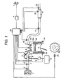
- the internal combustion engine unit in accordance with the present invention is composed of an engine 99 capable of performing lean burn operation, an air intake system having an air cleaner 1, a throttle valve 3, an air intake pipe 11 and so on, an exhaust gas purifying system having an exhaust gas pipe 18, an NO x purifying catalyst 19 and so on, and a control unit (ECU) 25.
- the control unit 25 is composed of, not shown in the figure, an I/O LSI as an input-output interface, a micro-processing unit MPU, memory units RAM and ROM for storing a plurality of control programs, a timer counter and so on.
- Fuel in a fuel tank 13 is conducted to an injector 5 arranged in the air intake system of the engine through a fuel pump 12.
- An air flow sensor 2, a throttle opening sensor 4 and an intake air temperature sensor 9 are arranged in the air intake system, and an output signal of each of the sensors is input to the control unit 25.
- An oxygen sensor 20, an NO X concentration sensor 21, an NO x purifying catalyst temperature sensor 22 and an exhaust gas temperature sensor 23 are arranged in the exhaust gas purifying system, and an output signal of each of the sensors is also input to the control unit 25.
- output signals of a knock sensor 26, a water temperature sensor 28, a crank angle sensor 29 for detecting a rotating speed of the engine 99 and a load sensor 8 for detecting an engine load based on a stepping amount of an accelerator pedal 7 are also input to the control unit 25.
- the control unit 25 evaluates an operating state of the internal combustion engine 99 and a state of the NO X purifying catalyst 19 based on the signals of the sensors described above and determines an operating air-to-fuel ratio using an air-to-fuel ratio control means (not shown in the figure), and controls the fuel concentration of the mixed gas so as to set the fuel concentration to a desired value by controlling an injection time period of the injector 5 and so on.
- the mixed gas sucked in a combustion chamber 99a is fired and burned by an ignition plug 6 controlled by a signal from the control unit 25.
- the NO X purifying capability of the NO X purifying catalyst is judged by a control judgment and a control signal of the aforementioned air-to-fuel ratio control means.
- the NO X adsorbing-capturing capability is decreased, the NO X adsorbing-capturing capability of the NO X purifying catalyst 19 is recovered by controlling the air-to-fuel ratio for combustion so as to become stoichiometric or rich.
- the apparatus of the embodiment can effectively purify the exhaust gas under all the conditions of combustion operations of the engine, including lean operation and stoichiometric (including rich) operation.
- the NO X purifying catalyst N-N was prepared through the following method. That is, a honeycomb made of cordierite as a base body of the honeycomb catalyst was coated with alumina of 150 g per 1 L apparent volume. A honeycomb shaped catalyst was obtained by supporting catalytic active components onto the alumina coated honeycomb.
- the alumina coated honeycomb was firstly impregnated with a solution of cerium nitrate (Ce(NO 3 ) 2 ) and calcined for 1 hour at 600 °C after being dried, and then impregnated with a mixed solution of a solution of sodium nitrate (NaNO 3 ), a solution of titania-sol and a solution of magnesium nitrate (Mg(NO 3 ) 2 ), and also dried and calcined.
- Ce(NO 3 ) 2 cerium nitrate
- NaNO 3 sodium nitrate
- Mg(NO 3 ) 2 magnesium nitrate
- the honeycomb shaped NO X purifying catalyst 2Mg-(0.2Rh, 2.7Pt)-(18Na, 4Ti, 2Mg)-27Ce/Al 2 O 3 which had Ce, Mg, Na, Ti, Rh, Pt supported on the alumina (Al 2 O 3 ) was obtained.
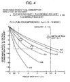
- the ratio of reducing fuel consumption rate of a vehicle employing lean burn system is generally 10 % or more. Taking this into consideration, it can be said that the ratio of decreases in the fuel consumption rate by the rich shift should be suppressed to 5 % or less.
Landscapes
- Engineering & Computer Science (AREA)
- Chemical & Material Sciences (AREA)
- Combustion & Propulsion (AREA)
- Mechanical Engineering (AREA)
- General Engineering & Computer Science (AREA)
- Chemical Kinetics & Catalysis (AREA)
- Analytical Chemistry (AREA)
- Environmental & Geological Engineering (AREA)
- Biomedical Technology (AREA)
- General Chemical & Material Sciences (AREA)
- Oil, Petroleum & Natural Gas (AREA)
- Health & Medical Sciences (AREA)
- Exhaust Gas After Treatment (AREA)
- Exhaust Gas Treatment By Means Of Catalyst (AREA)
- Catalysts (AREA)
- Electrical Control Of Air Or Fuel Supplied To Internal-Combustion Engine (AREA)
Claims (5)
- Procédé de production d'un catalyseur de purification des NOx, qui est fait en une composition comprenant au moins un type d'élément sélectionné dans le groupe constitué des métaux alcalins et des métaux alcalino-terreux, au moins un type d'élément sélectionné dans le groupe constitué des métaux de terres rares, au moins un type d'élément sélectionné dans le groupe constitué des métaux précieux et du titane, ladite composition étant supportée sur un oxyde métallique poreux thermorésistant, dans lequel le catalyseur adsorbe les NOx dans le gaz d'échappement sur une surface de celui-ci, quand le gaz d'échappement est pauvre et réduit les NOx adsorbés en N2 quand le gaz d'échappement est stoechiométrique ou riche, ledit procédé comprenant les étapes consistant à :(a) enduire un corps de base avec l'oxyde métallique poreux thermorésistant,(b) imprégner le corps de base revêtu avec une solution de nitrate de cérium, sécher le corps de base revêtu imprégné et puis le calciner pendant 1 heure à 600° C,(c) imprégner le corps de base revêtu avec une solution mixte d'une solution de sol de dioxyde de titane, d'une solution de nitrate de sodium et d'une solution de nitrate de magnésium, ou avec une solution mixte d'une solution de sol de dioxyde de titane et d'une solution de nitrate de strontium, sécher le corps de base revêtu imprégné et puis le calciner ;(d) imprégner le corps de base revêtu avec une solution mixte d'une solution de nitrate de platine de dinitrodiamine et d'une solution de nitrate de rhodium, sécher le corps de base revêtu imprégné et puis le calciner pendant 1 heure à 450°C ;(e) imprégner le corps de base revêtu avec une solution de nitrate de magnésium, sécher le corps de base revêtu imprégné et puis le calciner pendant 1 heure à 450°C.
- Dispositif pour la purification d'un gaz d'échappement d'un moteur à combustion interne comprenant un catalyseur de purification des NOx disposé dans un conduit de gaz d'échappement et une unité de commande, dans lequel- le catalyseur de purification des NOx peut être obtenu selon la revendication 1,- le catalyseur de purification des NOx adsorbe les NOx dans le gaz d'échappement sur la surface de celui-ci quand le gaz d'échappement est pauvre et réduit les NOx adsorbés en N2 quand le gaz d'échappement est stoechiométrique ou riche, et- l'unité de commande possède un moyen de régulation du rapport air/carburant, ledit moyen de régulation du rapport air/carburant ayant des moyens pour réguler le gaz d'échappement en direction d'un état stoechiométrique ou d'un état riche pendant 0.5 seconde à 4.5 secondes pour purifier le gaz d'échappement en réduisant les NOx adsorbés sur ledit catalyseur de purification des NOx en N2 par le biais d'une réaction catalytique avec un agent réducteur.
- Dispositif selon la revendication 2, dans lequel, dans ladite régulation du gaz d'échappement en direction d'un état stoechiométrique ou d'un état riche, une profondeur dudit état riche est située entre 13.0 et 14.7 en rapport air/carburant A/F.
- Utilisation du dispositif pour la purification d'un gaz d'échappement d'un moteur à combustion interne selon la revendication 3 dans un procédé comprenant les étapes consistant à :- disposer ledit dispositif dans un conduit de gaz d'échappement,- fournir une unité de commande ayant des moyens de régulation du rapport air/carburant ayant des moyens permettant de réguler le gazo d'échappement en direction d'un état stoechiométrique ou d'un état riche,- faire fonctionner le moteur à combustion interne sous un régime pauvre, dans lequel le gaz d'échappement est purifié par adsorption des NOx dans le gaz d'échappement sur ledit catalyseur de purification des NOx et- paramétrer, après adsorption, le gaz d'échappement en un état stoechiométrique ou un état riche pendant 0.5 seconde à 4.5 secondes pour réduire les NOx adsorbés sur ledit catalyseur de purification des NOx en N2 par le biais d'une réaction catalytique avec un agent réducteur.
- Utilisation selon la revendication 4, dans laquelle le rapport air/carburant A/F est paramétré à une valeur située dans la plage allant de 13.0 à 14.7 quand le gaz d'échappement est régulé vers l'état stoechiométrique ou l'état riche.
Applications Claiming Priority (2)
| Application Number | Priority Date | Filing Date | Title |
|---|---|---|---|
| JP33902897 | 1997-12-09 | ||
| JP33902897A JP4464472B2 (ja) | 1997-12-09 | 1997-12-09 | 内燃機関の排ガス浄化方法及び浄化装置 |
Publications (3)
| Publication Number | Publication Date |
|---|---|
| EP0922840A2 EP0922840A2 (fr) | 1999-06-16 |
| EP0922840A3 EP0922840A3 (fr) | 1999-11-24 |
| EP0922840B1 true EP0922840B1 (fr) | 2007-08-01 |
Family
ID=18323594
Family Applications (1)
| Application Number | Title | Priority Date | Filing Date |
|---|---|---|---|
| EP98123042A Expired - Lifetime EP0922840B1 (fr) | 1997-12-09 | 1998-12-08 | Procédé de production d'un catalyseur de purification des NOx et dispositif pour la purification de gaz d'échappement d'un moteur à combustion interne |
Country Status (5)
| Country | Link |
|---|---|
| US (1) | US6305161B1 (fr) |
| EP (1) | EP0922840B1 (fr) |
| JP (1) | JP4464472B2 (fr) |
| CA (1) | CA2255889C (fr) |
| DE (1) | DE69838165T2 (fr) |
Families Citing this family (10)
| Publication number | Priority date | Publication date | Assignee | Title |
|---|---|---|---|---|
| CN1095028C (zh) * | 1997-04-09 | 2002-11-27 | 发射技术有限公司 | 监控NOx存储器的方法和设备 |
| FR2787037B1 (fr) | 1998-12-09 | 2002-01-11 | Inst Francais Du Petrole | Procede et dispositif d'elimination des oxydes d'azote dans une ligne d'echappement de moteur a combustion interne |
| JP3613676B2 (ja) * | 2000-07-24 | 2005-01-26 | トヨタ自動車株式会社 | 内燃機関の排気浄化装置 |
| JP3711329B2 (ja) * | 2001-02-01 | 2005-11-02 | ミヤマ株式会社 | 車両運転状態評価システム |
| JP3870783B2 (ja) * | 2001-12-27 | 2007-01-24 | 日産自動車株式会社 | 燃料電池自動車用排ガス浄化システムおよび燃料電池自動車の排ガスの浄化方法 |
| JP4182878B2 (ja) * | 2003-10-09 | 2008-11-19 | トヨタ自動車株式会社 | 内燃機関の空燃比制御装置 |
| US7399729B2 (en) | 2003-12-22 | 2008-07-15 | General Electric Company | Catalyst system for the reduction of NOx |
| US8156732B2 (en) * | 2006-03-24 | 2012-04-17 | Fleetguard, Inc. | Apparatus, system, and method for regenerating an exhaust gas treatment device |
| CN100427205C (zh) * | 2006-09-06 | 2008-10-22 | 天津化工研究设计院 | 一种降低冷起动尾气排放净化催化剂的制备方法 |
| US9365109B2 (en) | 2012-06-22 | 2016-06-14 | Bemis Manufacturing Company | Cap with adsorption media |
Citations (3)
| Publication number | Priority date | Publication date | Assignee | Title |
|---|---|---|---|---|
| EP0335847A1 (fr) * | 1988-03-07 | 1989-10-04 | W.C. Heraeus GmbH | Catalyseur pour purifier les gaz d'échappement des moteurs à combustion interne sa préparation et son utilisation |
| EP0666099A1 (fr) * | 1993-04-28 | 1995-08-09 | Nippon Shokubai Co., Ltd. | Procede pour eliminer des oxydes d'azote contenus dans des gaz d'echappement |
| EP0838255A2 (fr) * | 1996-10-25 | 1998-04-29 | Hitachi, Ltd. | Catalyseur pour purifier le gaz d'échappement d'un moteur à combustion interne et méthode de purification |
Family Cites Families (12)
| Publication number | Priority date | Publication date | Assignee | Title |
|---|---|---|---|---|
| JPS6297630A (ja) | 1985-10-24 | 1987-05-07 | Nippon Shokubai Kagaku Kogyo Co Ltd | 窒素酸化物含有ガスから窒素酸化物を除去する方法 |
| JPS62106826A (ja) | 1985-11-06 | 1987-05-18 | Nippon Shokubai Kagaku Kogyo Co Ltd | デイ−ゼル排ガス中の窒素酸化物を除去する方法 |
| JPS62117620A (ja) | 1985-11-19 | 1987-05-29 | Nippon Shokubai Kagaku Kogyo Co Ltd | ガソリンエンジン排ガス中の窒素酸化物を除去する方法 |
| US5296198A (en) * | 1990-11-09 | 1994-03-22 | Ngk Insulators, Ltd. | Heater and catalytic converter |
| JP2600492B2 (ja) | 1991-10-03 | 1997-04-16 | トヨタ自動車株式会社 | 内燃機関の排気浄化装置 |
| EP0625633B1 (fr) * | 1992-12-03 | 2000-03-15 | Toyota Jidosha Kabushiki Kaisha | Epurateur de gaz d'echappement pour moteurs a combustion interne |
| EP0707882A1 (fr) * | 1994-10-21 | 1996-04-24 | Toyota Jidosha Kabushiki Kaisha | Catalyseur pour la purification de gaz d'échappement |
| JP3664182B2 (ja) * | 1994-12-19 | 2005-06-22 | トヨタ自動車株式会社 | 高耐熱性排ガス浄化用触媒とその製造方法 |
| DE19543219C1 (de) * | 1995-11-20 | 1996-12-05 | Daimler Benz Ag | Verfahren zum Betreiben eines Dieselmotors |
| JPH09201531A (ja) * | 1996-01-29 | 1997-08-05 | Toyota Central Res & Dev Lab Inc | 排ガス浄化用触媒及び排ガス浄化方法 |
| US6025297A (en) * | 1996-11-14 | 2000-02-15 | Toyota Jidosha Kabushiki Kaisha | Catalyst for purifying exhaust gas and process for producing the same |
| JPH10169434A (ja) * | 1996-12-09 | 1998-06-23 | Ngk Insulators Ltd | 排ガス浄化方法及びそれに用いる排ガス浄化システム |
-
1997
- 1997-12-09 JP JP33902897A patent/JP4464472B2/ja not_active Expired - Fee Related
-
1998
- 1998-12-07 CA CA002255889A patent/CA2255889C/fr not_active Expired - Fee Related
- 1998-12-08 DE DE69838165T patent/DE69838165T2/de not_active Expired - Lifetime
- 1998-12-08 EP EP98123042A patent/EP0922840B1/fr not_active Expired - Lifetime
- 1998-12-09 US US09/207,600 patent/US6305161B1/en not_active Expired - Lifetime
Patent Citations (3)
| Publication number | Priority date | Publication date | Assignee | Title |
|---|---|---|---|---|
| EP0335847A1 (fr) * | 1988-03-07 | 1989-10-04 | W.C. Heraeus GmbH | Catalyseur pour purifier les gaz d'échappement des moteurs à combustion interne sa préparation et son utilisation |
| EP0666099A1 (fr) * | 1993-04-28 | 1995-08-09 | Nippon Shokubai Co., Ltd. | Procede pour eliminer des oxydes d'azote contenus dans des gaz d'echappement |
| EP0838255A2 (fr) * | 1996-10-25 | 1998-04-29 | Hitachi, Ltd. | Catalyseur pour purifier le gaz d'échappement d'un moteur à combustion interne et méthode de purification |
Also Published As
| Publication number | Publication date |
|---|---|
| JP4464472B2 (ja) | 2010-05-19 |
| CA2255889C (fr) | 2002-10-22 |
| DE69838165D1 (de) | 2007-09-13 |
| US6305161B1 (en) | 2001-10-23 |
| CA2255889A1 (fr) | 1999-06-09 |
| EP0922840A3 (fr) | 1999-11-24 |
| EP0922840A2 (fr) | 1999-06-16 |
| DE69838165T2 (de) | 2008-04-17 |
| JPH11173181A (ja) | 1999-06-29 |
Similar Documents
| Publication | Publication Date | Title |
|---|---|---|
| US6397582B1 (en) | Exhaust gas purification apparatus of internal combustion engine and catalyst for purifying exhaust gas of internal combustion engine | |
| EP0896134B1 (fr) | Système de purification de gaz d'échappement d' un moteur | |
| EP0922840B1 (fr) | Procédé de production d'un catalyseur de purification des NOx et dispositif pour la purification de gaz d'échappement d'un moteur à combustion interne | |
| JP3613083B2 (ja) | 排気浄化制御装置 | |
| US20020050135A1 (en) | Apparatus for purifying and controlling exhaust gases | |
| JP3746179B2 (ja) | 内燃機関の排ガス浄化装置 | |
| JP3414323B2 (ja) | 内燃機関の排気浄化装置 | |
| JP4147702B2 (ja) | 内燃機関の排ガス浄化用NOx吸着触媒 | |
| JP2004100483A (ja) | 排気ガス浄化方法 | |
| JPH11190210A (ja) | 排ガス浄化制御装置 | |
| JP3107303B2 (ja) | 内燃機関の排ガス浄化装置 | |
| JPH1181988A (ja) | 内燃機関の排ガス浄化装置 | |
| JP2002115534A (ja) | 内燃機関の排ガス浄化装置 | |
| JP3896224B2 (ja) | 内燃機関の制御装置 | |
| JP3896223B2 (ja) | 内燃機関の排ガス浄化装置 | |
| JP3661555B2 (ja) | 排気ガス浄化システム | |
| JP2001050033A (ja) | 排気浄化制御装置 |
Legal Events
| Date | Code | Title | Description |
|---|---|---|---|
| PUAI | Public reference made under article 153(3) epc to a published international application that has entered the european phase |
Free format text: ORIGINAL CODE: 0009012 |
|
| AK | Designated contracting states |
Kind code of ref document: A2 Designated state(s): DE FR GB |
|
| AX | Request for extension of the european patent |
Free format text: AL;LT;LV;MK;RO;SI |
|
| PUAL | Search report despatched |
Free format text: ORIGINAL CODE: 0009013 |
|
| AK | Designated contracting states |
Kind code of ref document: A3 Designated state(s): AT BE CH CY DE DK ES FI FR GB GR IE IT LI LU MC NL PT SE |
|
| AX | Request for extension of the european patent |
Free format text: AL;LT;LV;MK;RO;SI |
|
| RIC1 | Information provided on ipc code assigned before grant |
Free format text: 6B 01D 53/94 A, 6F 02D 41/02 B, 6F 01N 3/08 B |
|
| 17P | Request for examination filed |
Effective date: 20000316 |
|
| AKX | Designation fees paid |
Free format text: DE FR GB |
|
| 17Q | First examination report despatched |
Effective date: 20030714 |
|
| GRAP | Despatch of communication of intention to grant a patent |
Free format text: ORIGINAL CODE: EPIDOSNIGR1 |
|
| RTI1 | Title (correction) |
Free format text: METHOD FOR PRODUCING AN NOX-PURIFYING CATALYST AND APPARATUS FOR PURIFYING EXHAUST GAS OF AN INTERNAL COMBUSTION ENGINE |
|
| GRAS | Grant fee paid |
Free format text: ORIGINAL CODE: EPIDOSNIGR3 |
|
| GRAA | (expected) grant |
Free format text: ORIGINAL CODE: 0009210 |
|
| RAP1 | Party data changed (applicant data changed or rights of an application transferred) |
Owner name: HONDA GIKEN KOGYO KABUSHIKI KAISHA Owner name: HITACHI, LTD. |
|
| AK | Designated contracting states |
Kind code of ref document: B1 Designated state(s): DE FR GB |
|
| REG | Reference to a national code |
Ref country code: GB Ref legal event code: FG4D |
|
| REF | Corresponds to: |
Ref document number: 69838165 Country of ref document: DE Date of ref document: 20070913 Kind code of ref document: P |
|
| ET | Fr: translation filed | ||
| PLBE | No opposition filed within time limit |
Free format text: ORIGINAL CODE: 0009261 |
|
| STAA | Information on the status of an ep patent application or granted ep patent |
Free format text: STATUS: NO OPPOSITION FILED WITHIN TIME LIMIT |
|
| 26N | No opposition filed |
Effective date: 20080506 |
|
| PGFP | Annual fee paid to national office [announced via postgrant information from national office to epo] |
Ref country code: GB Payment date: 20101119 Year of fee payment: 13 |
|
| PGFP | Annual fee paid to national office [announced via postgrant information from national office to epo] |
Ref country code: FR Payment date: 20120105 Year of fee payment: 14 |
|
| REG | Reference to a national code |
Ref country code: DE Ref legal event code: R082 Ref document number: 69838165 Country of ref document: DE Representative=s name: BEETZ & PARTNER PATENT- UND RECHTSANWAELTE, DE |
|
| REG | Reference to a national code |
Ref country code: DE Ref legal event code: R082 Ref document number: 69838165 Country of ref document: DE Representative=s name: BEETZ & PARTNER MBB PATENT- UND RECHTSANWAELTE, DE Effective date: 20121219 Ref country code: DE Ref legal event code: R082 Ref document number: 69838165 Country of ref document: DE Representative=s name: BEETZ & PARTNER MBB PATENTANWAELTE, DE Effective date: 20121219 Ref country code: DE Ref legal event code: R082 Ref document number: 69838165 Country of ref document: DE Representative=s name: BEETZ & PARTNER MBB, DE Effective date: 20121219 Ref country code: DE Ref legal event code: R082 Ref document number: 69838165 Country of ref document: DE Representative=s name: BEETZ & PARTNER PATENT- UND RECHTSANWAELTE, DE Effective date: 20121219 Ref country code: DE Ref legal event code: R081 Ref document number: 69838165 Country of ref document: DE Owner name: HONDA GIKEN KOGYO K.K., JP Free format text: FORMER OWNERS: HONDA GIKEN KOGYO K.K., TOKYO, JP; HITACHI, LTD., TOKYO, JP Effective date: 20121219 Ref country code: DE Ref legal event code: R081 Ref document number: 69838165 Country of ref document: DE Owner name: HONDA GIKEN KOGYO K.K., JP Free format text: FORMER OWNER: HONDA GIKEN KOGYO K.K., HITACHI, LTD., , JP Effective date: 20121219 |
|
| GBPC | Gb: european patent ceased through non-payment of renewal fee |
Effective date: 20121208 |
|
| REG | Reference to a national code |
Ref country code: FR Ref legal event code: ST Effective date: 20130830 |
|
| PG25 | Lapsed in a contracting state [announced via postgrant information from national office to epo] |
Ref country code: GB Free format text: LAPSE BECAUSE OF NON-PAYMENT OF DUE FEES Effective date: 20121208 Ref country code: FR Free format text: LAPSE BECAUSE OF NON-PAYMENT OF DUE FEES Effective date: 20130102 |
|
| REG | Reference to a national code |
Ref country code: DE Ref legal event code: R084 Ref document number: 69838165 Country of ref document: DE |
|
| REG | Reference to a national code |
Ref country code: DE Ref legal event code: R084 Ref document number: 69838165 Country of ref document: DE Effective date: 20140821 |
|
| PGFP | Annual fee paid to national office [announced via postgrant information from national office to epo] |
Ref country code: DE Payment date: 20151201 Year of fee payment: 18 |
|
| REG | Reference to a national code |
Ref country code: DE Ref legal event code: R119 Ref document number: 69838165 Country of ref document: DE |
|
| PG25 | Lapsed in a contracting state [announced via postgrant information from national office to epo] |
Ref country code: DE Free format text: LAPSE BECAUSE OF NON-PAYMENT OF DUE FEES Effective date: 20170701 |