EP0924103A2 - Bogenverarbeitungsvorrichtung - Google Patents
Bogenverarbeitungsvorrichtung Download PDFInfo
- Publication number
- EP0924103A2 EP0924103A2 EP98124032A EP98124032A EP0924103A2 EP 0924103 A2 EP0924103 A2 EP 0924103A2 EP 98124032 A EP98124032 A EP 98124032A EP 98124032 A EP98124032 A EP 98124032A EP 0924103 A2 EP0924103 A2 EP 0924103A2
- Authority
- EP
- European Patent Office
- Prior art keywords
- sheet
- sheets
- processing apparatus
- reference surface
- transporting
- Prior art date
- Legal status (The legal status is an assumption and is not a legal conclusion. Google has not performed a legal analysis and makes no representation as to the accuracy of the status listed.)
- Granted
Links
- 238000012545 processing Methods 0.000 title claims abstract description 48
- 230000033001 locomotion Effects 0.000 claims abstract description 7
- 238000000034 method Methods 0.000 claims description 39
- 238000007599 discharging Methods 0.000 claims description 11
- 238000011144 upstream manufacturing Methods 0.000 claims description 5
- 230000007306 turnover Effects 0.000 claims 1
- 230000008878 coupling Effects 0.000 description 7
- 238000010168 coupling process Methods 0.000 description 7
- 238000005859 coupling reaction Methods 0.000 description 7
- 238000005452 bending Methods 0.000 description 1
- 230000005540 biological transmission Effects 0.000 description 1
- 238000007730 finishing process Methods 0.000 description 1
- 230000007257 malfunction Effects 0.000 description 1
- 238000004519 manufacturing process Methods 0.000 description 1
- 239000002184 metal Substances 0.000 description 1
- 230000010355 oscillation Effects 0.000 description 1
- 230000002093 peripheral effect Effects 0.000 description 1
- 238000004080 punching Methods 0.000 description 1
- 230000001105 regulatory effect Effects 0.000 description 1
- 239000011347 resin Substances 0.000 description 1
- 229920005989 resin Polymers 0.000 description 1
- 230000008961 swelling Effects 0.000 description 1
Images


Classifications
-
- B—PERFORMING OPERATIONS; TRANSPORTING
- B65—CONVEYING; PACKING; STORING; HANDLING THIN OR FILAMENTARY MATERIAL
- B65H—HANDLING THIN OR FILAMENTARY MATERIAL, e.g. SHEETS, WEBS, CABLES
- B65H31/00—Pile receivers
- B65H31/30—Arrangements for removing completed piles
- B65H31/3081—Arrangements for removing completed piles by acting on edge of the pile for moving it along a surface, e.g. by pushing
-
- B—PERFORMING OPERATIONS; TRANSPORTING
- B42—BOOKBINDING; ALBUMS; FILES; SPECIAL PRINTED MATTER
- B42C—BOOKBINDING
- B42C1/00—Collating or gathering sheets combined with processes for permanently attaching together sheets or signatures or for interposing inserts
- B42C1/12—Machines for both collating or gathering and permanently attaching together the sheets or signatures
-
- B—PERFORMING OPERATIONS; TRANSPORTING
- B65—CONVEYING; PACKING; STORING; HANDLING THIN OR FILAMENTARY MATERIAL
- B65H—HANDLING THIN OR FILAMENTARY MATERIAL, e.g. SHEETS, WEBS, CABLES
- B65H29/00—Delivering or advancing articles from machines; Advancing articles to or into piles
- B65H29/02—Delivering or advancing articles from machines; Advancing articles to or into piles by mechanical grippers engaging the leading edge only of the articles
- B65H29/06—Delivering or advancing articles from machines; Advancing articles to or into piles by mechanical grippers engaging the leading edge only of the articles the grippers being carried by rotating members
-
- B—PERFORMING OPERATIONS; TRANSPORTING
- B65—CONVEYING; PACKING; STORING; HANDLING THIN OR FILAMENTARY MATERIAL
- B65H—HANDLING THIN OR FILAMENTARY MATERIAL, e.g. SHEETS, WEBS, CABLES
- B65H31/00—Pile receivers
- B65H31/04—Pile receivers with movable end support arranged to recede as pile accumulates
- B65H31/08—Pile receivers with movable end support arranged to recede as pile accumulates the articles being piled one above another
- B65H31/10—Pile receivers with movable end support arranged to recede as pile accumulates the articles being piled one above another and applied at the top of the pile
-
- B—PERFORMING OPERATIONS; TRANSPORTING
- B65—CONVEYING; PACKING; STORING; HANDLING THIN OR FILAMENTARY MATERIAL
- B65H—HANDLING THIN OR FILAMENTARY MATERIAL, e.g. SHEETS, WEBS, CABLES
- B65H2301/00—Handling processes for sheets or webs
- B65H2301/10—Selective handling processes
- B65H2301/16—Selective handling processes of discharge in bins, stacking, collating or gathering
- B65H2301/163—Bound or non bound, e.g. stapled or non stapled stacking mode
-
- B—PERFORMING OPERATIONS; TRANSPORTING
- B65—CONVEYING; PACKING; STORING; HANDLING THIN OR FILAMENTARY MATERIAL
- B65H—HANDLING THIN OR FILAMENTARY MATERIAL, e.g. SHEETS, WEBS, CABLES
- B65H2301/00—Handling processes for sheets or webs
- B65H2301/40—Type of handling process
- B65H2301/42—Piling, depiling, handling piles
- B65H2301/422—Handling piles, sets or stacks of articles
- B65H2301/4222—Squaring-up piles
-
- B—PERFORMING OPERATIONS; TRANSPORTING
- B65—CONVEYING; PACKING; STORING; HANDLING THIN OR FILAMENTARY MATERIAL
- B65H—HANDLING THIN OR FILAMENTARY MATERIAL, e.g. SHEETS, WEBS, CABLES
- B65H2301/00—Handling processes for sheets or webs
- B65H2301/40—Type of handling process
- B65H2301/42—Piling, depiling, handling piles
- B65H2301/422—Handling piles, sets or stacks of articles
- B65H2301/4226—Delivering, advancing piles
- B65H2301/42266—Delivering, advancing piles by acting on edge of the pile for moving it along a surface, e.g. pushing
-
- B—PERFORMING OPERATIONS; TRANSPORTING
- B65—CONVEYING; PACKING; STORING; HANDLING THIN OR FILAMENTARY MATERIAL
- B65H—HANDLING THIN OR FILAMENTARY MATERIAL, e.g. SHEETS, WEBS, CABLES
- B65H2405/00—Parts for holding the handled material
- B65H2405/10—Cassettes, holders, bins, decks, trays, supports or magazines for sheets stacked substantially horizontally
- B65H2405/11—Parts and details thereof
- B65H2405/111—Bottom
- B65H2405/1116—Bottom with means for changing geometry
- B65H2405/11161—Bottom with means for changing geometry by at least a protruding portion arrangement
Definitions
- This invention relates to a sheet processing apparatus which receives sheets whereon an image is formed by an image forming apparatus such as an electrophotographic copying machine, a printer, or a printing machine and discharges them onto a receiving tray by a discharging means after finishing processes such as inverting upside down, stacking, and binding together.
- an image forming apparatus such as an electrophotographic copying machine, a printer, or a printing machine
- a sheet processing apparatus For an apparatus which collates a plurality of sheets with an image formed by an image forming apparatus ejected from the apparatus for each set of copies and binds them with a stapler, a sheet processing apparatus, called as a finisher, is used.
- This finisher is functionally connected to an image forming apparatus such as a copying machine, or a printer, and is designed to be driven corresponding to the sequential operation of the copying or printing process.
- the sheets with an image formed on them, conveyed out of the image forming apparatus mainframe, are successively stacked in an intermediate stacking plate in the collated order, and are subjected to sheet processings such as stapling, etc., after a set of copy sheets are stacked.
- the bound set of copy sheets are carried on the discharging belt provided at the bottom of said intermediate stacking plate, transported, held between a pair of upper-and-lower ejecting rollers, and are discharged onto the receiving tray.
- the sheet processing apparatus described in the Japanese laid open patent H8-42728 is provided with a stapler and a receiving tray corresponding to it. Further, the sheet processing apparatus described in the Japanese laid open patent H7-76190 is provided with two staplers and two receiving trays corresponding to them.
- the sheet inverting system described in the Japanese laid open patent H8-85663 has two different positions for positioning the leading edge of sheets, at the first of which stapling is carried out, and at the second stapling is not carried out; these two different positions are determined by a movable finger for position adjusting.
- the tray apparatus described in the Japanese laid open patent H1-181672 is provided with a stopping portion made up of a soft member for stopping the trailing edge of the paper sheets stacked on the receiving tray and an urging member for urging one end portion of said soft member upward.
- the sheets with an image formed on them, conveyed out of the image forming apparatus are subjected or not subjected to the processings by the sheet processing means (including stapler, shifting means, bookbinding means, punching means, etc.), transported, and ejected onto the receiving tray by the discharging means, where they are sliding down along the tilted surface of the tray until their trailing edges collide with the stopper to be stopped there.
- the sheets which are not to be subjected such processings are directly ejected onto the fixedly attached tray where they are sliding down the tilted surface of the tray until their trailing edges collide with the stopper to be stopped there.
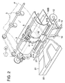
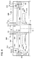
- Fig. 1 is a cross-sectional view showing the structure of the above-mentioned sheet processing apparatus (finisher).
- Fig. 2 is a perspective view of the sheet inverting-transporting portion and the paper ejecting portion of said sheet processing apparatus.
- the aforesaid sheet processing apparatus is installed with its position and level adjusted in a manner such that the receiving portion for the sheet P is coincide with the paper ejecting exit of the image forming apparatus (such as a copying machine or a printer) mainframe, and is connected to the control system so as to be driven corresponding to the operation of the image forming apparatus mainframe.
- the image forming apparatus such as a copying machine or a printer
- Sheet P ejected by the pair of ejecting rollers R101 of image forming apparatus mainframe 100 passes the upper transport path by the switching of switching gate 1 of the aforesaid receiving portion, and is ejected to receiving tray 10 fixedly arranged at the uppermost stage of the sheet processing apparatus, held between the pair of ejecting rollers 2.
- sheet P which has passed lower transport path "b" by the switching of switching gate 1 of the aforesaid receiving portion, is transported by the pair of intermediate transport rollers 3 composed of a driving roller and a pinch roller, passing transport path "c" made up of a fixed guiding plate, and is further transported onto the circumferential surface of sheet transporting drum 4 held between the pair of transporting rollers 5 located above drum 4.
- Sheet transporting drum 4 is driven to rotate in the direction of the arrow by a driving source (not shown).
- sheet holding member 6 Near the circumferential surface of sheet transporting drum 4, sheet holding member 6 (hereinafter referred to as gripper 6) is supported to be able to oscillate.
- Gripper 6 is urged by a spring and is made to oscillate by a cam mechanism (not shown).
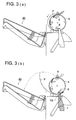
- Fig. 3 through Fig. 5 are partial cross-sectional views showing the process of sheet transport in the sheet processing apparatus.
- the sheet transport path for the sheet with an image formed on it is the same in both the stapling process mode and non-stapling process mode. Further, the reference surfaces for butting the leading edge of the sheet are set at the same positions in both the stapling process mode and non-stapling process mode.
- reference surfaces 7S are positioned inside the both side edges for all the sheet sizes discharged from image forming apparatus mainframe 100, even when sheet P is shifted to the direction perpendicular to the sheet transport direction.
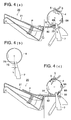
- Fig. 4(b) is a drawing showing the positional relationship between reference surfaces 7S of stopper 7 and sheet transporting drum 4.
- Reference surfaces 7S are positioned at the downstream side in the sheet transport direction from the position just under the rotational axis of sheet transporting drum 4 for holding the leading edge portion of the sheet to invert it. That is, distance L between the plumb line shown by the broken line just under the rotational axis of sheet transporting drum 4 and reference surfaces 7S is set at a predetermined distance, for example, approximately 10 mm downstream the sheet transport direction. Owing to this, the leading edge portion of sheet P held between spring-urged gripper 6 and sheet transporting drum 4 is reliably butted at the reference surfaces 7S to stop, and the gripper 6, which has released the sheet P, rotates together with sheet transporting drum 4 to be ready to the successive sheet holding.
- At least two reference surfaces 7S are arranged in the sheet width direction perpendicular to the sheet transport direction and are movable in the sheet width direction corresponding to the movement of staplers 50 under stapling process.
- reference surface 7S is formed to be a curved surface 7R bending to the sheet side.
- This curved surface 7R is formed to be a curved surface having a radius of curvature approximately 30 mm. Even if a number of transported sheets P, the leading edges of which are curved upward, are stacked, the leading edges of sheets P never rides over reference surfaces 7S, because the leading edge portion proceeding to stopper 7 is hindered by this curved surface 7R to be pressed downward.
- truing-up members 91 trues up sheets P in the width direction (direction perpendicular to the sheet transport direction) (width truing-up).
- truing-up members 91 are alternately shifted to the predetermined plural positions to make said width truing-up.
- Stopper 7 is fixed on the moving carriage of staplers 50, and is movable together with the staplers as a united member.
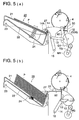
- Fig. 1 and Fig. 5(a) are drawings showing how sheet P, for which stapling-process or non-stapling process (shifting process, simple ejecting) is completed, is ejected onto sheet stacking plate 21 or onto fixed plate member 22.
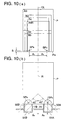
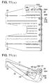
- Fig. 11(a) is the plan of the upper sheet receiving tray 20
- Fig. 11(b) is the front view of upper sheet receiving tray 20
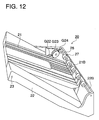
- Fig. 12 is a perspective view of upper sheet receiving tray 20.
- driving motor M5 of ejecting means 11 drives to rotate disk 12 through the drive transmitting system composed of timing belt TB1, gear G25, and gear G26.
- the other end of crank 13 with its one end supported at an eccentric position of disk 12, is supported by a shaft to be able to rotate freely at a part of ejecting arm 14 which is capable of oscillating around supporting shaft 15.
- Disk 12 driven to rotate by motor M5 makes crank 13 to move eccentrically and further makes ejecting arm 14 oscillate.
- front end portion 14A of ejecting arm 14 presses the leading edge portion of sheet P, for which the sheet processing is completed, to push it out from the position in contact with stopper 7 toward sheet receiving plate 21 and fixed plate member 22 of upper sheet receiving tray 20.
- Front end portion 14A of ejecting arm 14 comes forward to near the position just over sheet stopping surface 21B of sheet stacking plate 21; hence, the bundle of the sheets is reliably moved onto sheet stacking surface 21A of upper receiving tray 20.
- upper sheet receiving tray 20 and lower sheet receiving tray 30 have the same shape, upper sheet receiving tray 20 will be explained as the representative in the following.
- Upper sheet receiving tray 20 is composed of fixed plate member 22, sheet stacking plate 21, supporting shaft 23 attached to the fixed receiving plate for supporting one end of sheet stacking plate 21 to be able to oscillate around it, and spring 24 for urging upward the other end of sheet stacking plate 21.
- Sheet stacking surface 22A of fixed plate member 22 is formed to make an inclined surface in such a manner as to make the leading edge portion of the stacked sheets high and the trailing edge portion low.
- curved stopping surface portion 22B is formed integrally.
- Fixed plate member 22 is engaged with and fixed to the going-up-and-down means of the sheet processing apparatus mainframe and is driven to go up and down.
- Sheet stacking surface 21A of sheet stacking plate 21 is disposed between side walls 22A of the fixed plate member 22 positioned to the both sides of sheet stacking surface 21A, is engaged with the fixed plate by supporting shaft 23 to be able to oscillate, and is urged upward by spring member 24, with its engaging surface made to be in contact with the stopper (not shown), to be stopped at the upper limit position.
- the upper end of spring member 24 is positioned at the bottom of sheet stacking plate 21, and fixed by an engaging member.
- the lower end of spring member 24 is loosely fitted in the concave portion provided at the bottom of fixed plate member 22 for positioning.
- upper surface 14B of ejecting arm 14 is made to form a circular arc to extend to the rear direction.
- Fig. 5(b) is a drawing showing how a number of sheets P are ejected and stacked on sheet stacking plate 21 and fixed plate member 22, after being subjected to stapling process or non-stapling process.
- sheet stacking plate 21 oscillates around shaft 23 to go down against the urging force of spring member 24 due to the own weight of sheets P. In this case too, the leading edge portion of sheets P collides with sheet stopping surface 21B to be stopped and is trued up. In the process of the above-mentioned sheet stacking, no frictional resistance is given to the leading edge portion of sheets P to let sheet stacking plate 21 go down smoothly, because the leading edge portion of sheets P contacts with sheet stopping surface 21B of sheet stacking plate 21 capable of going up and down for truing up.
- ejecting rollers 27 are provided to be able to rotate for driving over sheet stopping surface 21B of sheet stacking plate 21 and over fixed plate member 22.
- Ejecting rollers 27 are formed of soft rollers having elasticity (sponge rollers) made up of a foamed resin or the like, and fixed on rotating shaft 28 through holding member 27A. These plural ejecting rollers 27 are disposed on rotating shaft 28. This rotating shaft 28 is supported to be able to rotate on the both side walls of fixed plate member 22 in the direction perpendicular to the sheet transport.
- Rotating shaft 28 rotates in the counter-clockwise direction shown in Fig. 11(b), with the driving force transmitted through the transmission system composed of gears G21, G22, G23, and G24 from driving motor M9 as a driving source.
- Upper sheet receiving tray 20 is composed of driving motor M9, drive-transmitting members G21 through G24, sheet stacking plate 21, fixed plate member 22, ejecting rollers 27, and so forth, these members forming a paper discharging unit integrally assembled together. Accordingly, this unit as a whole can be separately assembled, adjusted, and exchanged with the other unit apart from the sheet processing apparatus mainframe.
- Lower receiving tray means 30 is also made up as a unit in the same manner.
- ejecting rollers 27 start to be driven to rotate in the counter-clockwise direction by the actuation of driving motor M9.
- front end portion 14A presses the leading edge portion of sheet P to eject sheet P onto upper sheet receiving tray 20.
- the upper side surfaces of the rotating ejecting rollers contact with the lower side of sheet P to assist the transport of the leading edge portion of sheet P, making sheet P surely pass over sheet stopping surface 21B of upper sheet receiving tray 20.
- sheet P When sheet P is conveyed to the stacking surfaces of sheet stacking plate 21 by ejecting arm 14 and ejecting rollers 27, sheet P glides down along sheet stacking surface 21A arranged with inclination or along the surface of the preceding stacked sheets with its leading edge downward; further, the leading edge portion of the sheet is pressed and held between the lower side surfaces of the rotating ejecting rollers and the inclined surface, until it is forced to collide with stopping surface portion 21B of sheet stacking plate 21 and stopping surface portion 22B of fixed plate member 22 to be stopped, with the leading edge trued up.
- the control section drives driving motor M6 for making the trays going up and down in driving means 40 for making the trays going up and down to make upper sheet receiving tray 20 go up. That is, a series of gears, composed of gears G5, G6, G7, G8, G9, and G10, drive to rotate driving pulley 41, driven by driving motor M6. Around said driving pulley 41 and upper driven pulley 42, driving wire 43 is entrained. Driving wire 43 moves up and down in a vertical direction by means of driving pulley 41.
- the base portion of the framework of aforesaid upper sheet receiving tray 20 is fixed by a suspending metal fitting.
- Framework 26 of upper sheet receiving tray 20 and framework 36 of lower receiving tray 30 are coupled by coupling rod 45. That is, long slot portion 451 is bored in coupling rod 45, and pin 46 fixedly attached to framework 26 of upper sheet receiving tray 20 is inserted to slide in said slot. Further, the portion near the lower end of coupling rod 45 is fixed to framework 36 of lower sheet receiving tray 30.
- Fig. 6 is the front view of the shift truing-up means 9.
- Shift truing-up means 9 is composed of first unit 90A shown in the left side in the drawing, which moves one truing-up member 91A (hereinafter referred to as truing-up plate 91A), and second unit 90B shown in the right side in the drawing, which moves the other truing-up member 91B (hereinafter referred to as truing-up plate 91B). Because these two units 90A and 90B have substantially the same structure, in the following, first unit 90A will be explained as the representative.
- Truing-up plate 91A is fixed to carriage 94A, which is capable of straightly moving forward and backward sliding on guiding bar 93A supported fixedly in the unit encasing member serving also as intermediate receiving plate 92A.
- Said carriage 94A is fixed to a predetermined point of timing belt 97A, which is entrained around driving pulley 95A and driven pulley 96A, with fixing member 98A.
- Driving pulley 95A is driven to rotate by driving motor M7 of the driving source through gears G11 and G12.
- PS1A is the home position sensor.
- second unit 90 B is driven to move forward and backward by driving motor M8 of the other driving source through the aforesaid gears and timing belt 97B.
- truing-up plates 91A and 91B have their own driving motors respectively to be able to move independently.
- the intermediate plates are separately and fixedly provided as central intermediate plate 92 and intermediate plates 92A and 92B disposed at both sides of said central intermediate plate 92, and each upper surface of these intermediate plates 92, 92A, and 92B is flush with each other, forming the sheet stacking surface for sheets P.
- Ejecting arm 14 is provided to be capable of oscillating at the center of the paper width direction, which is perpendicular to the sheet transport direction, and end portion 14A of its upper portion is inserted into the clearance portions formed between central intermediate receiving plate 92 and intermediate plates 92A and 92B disposed at the left and right of central plate 92, with the upper portion of upper end portion 14A protruded out of the sheet stacking surface of intermediate plates 92A and 92B to a height higher than the topmost sheet at the largest limit of the stacked sheets specified.
- stoppers 7A and 7B engaging with the leading edge portion of sheet P for positioning, are provided at the outer sides of end portion 14A of ejecting arm 14 respectively one at the left and the other at the right, and are movable.
- the upper end of the end portion of stoppers 7A and 7B is specified to have approximately the same height as end portion 14A of ejecting arm 14.
- stopper 7A The base portion of stopper 7A is fixed to moving stage 51A which holds stapler 50A (stapling unit) and is movable.
- the base portion of stopper 7B is fixed to moving stage 51B which holds stapler 50B (stapling unit) and is movable. Accordingly, stoppers 7A and 7B move in the direction of the paper width with the straight movement of staplers 50A and 50B.
- stoppers 7A and 7B is provided at the inner sides of staplers 50A and 50B respectively, however, it may be appropriate to make positioning reliable by providing auxiliary stoppers at the outer sides of staplers 50A and 50B to engage with the both sides of large-sized sheets.
- Fig. 7 is a schematic plan showing the operation of truing-up plates 91A and 91B in stapling process.
- Fig. 7(a) shows how usual-sized sheet P1 is trued up for the width and staple-processed.
- truing-up plates 91A and 91B are removed from the initial positions where home position sensors PS1A and PS1B are disposed to the positions a little more distant than the paper width of sheet P1, where they wait for the sheets, by driving motors M7 and M8 which are used only for the plates respectively.
- Every time when sheet P1 is fed in the vicinity of staplers 50 they are removed to positions a little narrower than the paper width to strike the side edges of sheet P1 for width truing-up.
- the leading edge portion of sheet P1 is already trued up by being butted at reference surfaces 7S of stoppers 7A and 7B.
- any one or both of staples SP A and SP B is processed (stapling process) by any one or both of staplers 50A and 50B.
- the trailing edge portion of stapled sheets P1 is ejected onto sheet receiving tray 20 (or 30) by end portion 14A of oscillating ejecting arm 14.
- Fig. 7(b) shows how small-sized sheet P2 (B6 size, A6 size, etc., for example) is trued up for the width and staple-processed.
- Reference surfaces 7S of stoppers 7A and 7B are specified to be positioned at the inner sides of the both side edges of smallest-sized sheet P in the width direction.
- Fig. 7(c) is a plan showing the sheets of various sizes and the positions of stapling.
- Staplers 50A and 50B are removed by a driving source (not shown) and stop at the predetermined different positions respectively for each sheet size to process staples SP A and SP B .
- the stapling process is done after one of truing-up plates 91B is shifted to move sheet P2 to the other of truing-up plates 91A, because staplers 50A and 50B can not approach the specified stapling positions due to ejecting arm 14 and so forth disposed in the vicinity of the center.
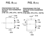
- Figs. 8(a) and 8(b) are schematic drawings showing the operation of truing-up plates 91A and 91B in shift processing.
- Fig. 8(a) shows how the bundle of the sheets of the odd-numbered order is processed.
- shift mode off-set mode
- truing-up plates 91A and 91B each of which is located at the initial position with an equal distance apart from central line R, move to the positions where are a little wider than the sheet width, maintaining the equal distance from central line R. Then, the bundle of the sheets is received, and ejected after processing.
- Fig. 8(b) shows how the bundle of the sheets of the even- numbered order is processed.
- truing-up plates 91A and 91B move until they stop at the positions which are at the distance unequal for each against central line R in the direction of the sheet transport, and ejected after processing.
- this shift mode it may be appropriate to make the aforesaid width truing-up.
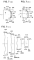
- Fig. 9 is a plan showing the process of moving of staplers 50A and 50B which force staple SP A or SP B into one end of leading edge portion Pa of sheets P of various sizes being in contact with stoppers 7A and 7B.
- Stapler 50A or 50B moves straight in the direction parallel to the leading edge of sheet Pa, keeping the positions disposed at 45° inclination, and forces staple SP A or SP B at the stapling positions of specified distances A 2 and A 3 .
- Fig. 10(a) is a plan showing how staples SP A and SP B are forced into the two points each positioned with an equal distance from central line R of sheets P of various sizes.
- Fig. 10(b) is a plan showing the arrangement of staplers 50A and 50B, which staple at the above-mentioned two points.
- Staplers 50A and 50B are disposed obliquely at the aforesaid home positions each being equally A 0 distant from central line R of sheet P (the positions shown by the broken lines in the drawing), however, when the two point stapling is instructed, they are rotated by the driving means, which will be described later, to be arranged in the positions parallel to central line R of sheet P, being in contact with stoppers 7A and 7B.
- the driving means which will be described later
- the sheet processing apparatus of this invention has a compact structure and its mechanism relating to the basis for sheet stopping is simplified, by making the sheet transport path and the reference surface for butting the leading edge of the sheet the same for both the stapling process mode and non-stapling process mode. Further, the position of sheet stopping is made accurate and stabilized for the smallest size through the largest size. Moreover, because the leading edge of the sheet always contacts with the reference surface for butting the leading edge of the sheet, even in case of shift truing-up, sheet truing-up is accurately carried out.
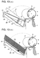
- Fig. 13(a) is a cross-sectional view showing the initial uprising state of the sheet stacking plate 21 on which sheets P are being stacked.
- the sheet stacking surface of sheet stacking plate 21 is made to be an inclined plane in a manner such that the downstream side in ejecting sheet P out of the outer peripheral surface of sheet transporting drum 4 is higher than the upstream side.
- the angle of inclination of the sheet receiving plate against horizontal plane ⁇ 3 is set to be not larger than 20°.
- the angle of inclination of sheet stacking plate 21 is larger than 20°, for example, if sheet stacking plate 21 is inclined plane 21' that is larger than inclination angle 20° shown by the single dot and dash line in the drawing, the trailing edge of sheet P of large size (for example, A3 size, 11_17 inch size, etc.) discharged from the nip position of transporting roller pair 5, after contacting with inclined plane 21', bends downward along inclined plane 21', to make a curl-shape as shown by the single dot and dash line P' in the drawing; further, the trailing edge of sheet P is made to have a shape as folded downward. If successive sheet P is fed onto inclined plane 21' in such a state of sheet with its trailing edge deformed, poor paper ejecting occurs.
- large size for example, A3 size, 11_17 inch size, etc.
- inclination angle ⁇ 3 of sheet stacking plate 21 is set to be not larger than 20° and not smaller than 10°.
- Fig. 13(b) is a cross-sectional view showing the going-down state of sheet stacking plate 21 on which the maximum number of sheets P are stacked.
- inclination angle ⁇ 4 of the sheet stacking plane of sheet stacking plate 21 against the horizontal plane is set to be not larger than 35°. If the angle of inclination ⁇ 4 of sheet stacking plate 21 is larger than 35°, as in the case of Fig.
- inclination angle ⁇ 4 of sheet stacking plate 21 should be most favorably not larger than 20°, but if it is not larger than 35°, when above-mentioned large-sized sheet P is stacked on sheet stacking plate 21, no problem will occur.
- inclination angle ⁇ 3 in the initial state is set to be not larger than 20°, and inclination angle ⁇ 4 in the last state to be not larger than 35°.
- the sheet processing apparatus connected to a copying machine is shown, however, the invention can be employed in the after-record processing apparatus that is used connected with an image forming apparatus such as a printer and a facsimile, a low-volume printer, or the like.
- the inclination angle of the sheet receiving plate is set to be not larger than 20° in the initial going-up state, and to be not larger than 35° in the going-down state where the maximum number of sheets are stacked, even when the large sized sheets are inverted and stacked, the poor paper ejecting such as folding, scattering, and jamming of the sheets is prevented.
- an elastic roller rotating for driving is provided over the sheet stopping surface which is provided at the upstream side in the direction of sheet ejection, and by the driving-rotation of this elastic roller, the sheet on the stacking surface of the sheet receiving plate is pressed and transported so as to make the leading edge of the sheet collide with the sheet stopping surface, the topmost sheet ejected onto the sheet receiving plate is reliably made to collide with the sheet stopping surface and trued up.
Landscapes
- Engineering & Computer Science (AREA)
- Mechanical Engineering (AREA)
- Folding Of Thin Sheet-Like Materials, Special Discharging Devices, And Others (AREA)
Applications Claiming Priority (4)
| Application Number | Priority Date | Filing Date | Title |
|---|---|---|---|
| JP9349425A JPH11180615A (ja) | 1997-12-18 | 1997-12-18 | シート後処理装置 |
| JP9349424A JPH11180626A (ja) | 1997-12-18 | 1997-12-18 | シート後処理装置 |
| JP34942597 | 1997-12-18 | ||
| JP34942497 | 1997-12-18 |
Publications (3)
| Publication Number | Publication Date |
|---|---|
| EP0924103A2 true EP0924103A2 (de) | 1999-06-23 |
| EP0924103A3 EP0924103A3 (de) | 2000-05-17 |
| EP0924103B1 EP0924103B1 (de) | 2004-03-31 |
Family
ID=26578945
Family Applications (1)
| Application Number | Title | Priority Date | Filing Date |
|---|---|---|---|
| EP98124032A Expired - Lifetime EP0924103B1 (de) | 1997-12-18 | 1998-12-17 | Bogenverarbeitungsvorrichtung |
Country Status (3)
| Country | Link |
|---|---|
| US (1) | US6283354B1 (de) |
| EP (1) | EP0924103B1 (de) |
| DE (1) | DE69822769D1 (de) |
Families Citing this family (16)
| Publication number | Priority date | Publication date | Assignee | Title |
|---|---|---|---|---|
| US6575446B2 (en) * | 1998-10-06 | 2003-06-10 | Konica Corporation | Image forming apparatus having sheet finisher |
| US6394442B1 (en) * | 2000-09-14 | 2002-05-28 | Xerox Corporation | Kicker with adjustable contact points, for a sheet output apparatus in a printer or copier |
| DE10311858B3 (de) * | 2003-03-17 | 2004-08-19 | Nexpress Solutions Llc | Vorrichtung zum Transport eines im wesentlichen bogenförmigen Elementes, insbesondere eines Bedruckstoffbogens |
| US20090166946A1 (en) * | 2007-12-27 | 2009-07-02 | Kabushiki Kaisha Toshiba | Sheet finishing apparatus |
| JP4497207B2 (ja) * | 2008-01-10 | 2010-07-07 | 富士ゼロックス株式会社 | 後処理装置 |
| JP2010058979A (ja) * | 2008-08-04 | 2010-03-18 | Ricoh Co Ltd | シート後処理装置及び画像形成装置 |
| US7857300B2 (en) * | 2008-09-10 | 2010-12-28 | Xerox Corporation | Apparatus and method for disk stacking and compiling media sheets |
| US7845531B2 (en) * | 2009-04-10 | 2010-12-07 | Kinpo Electronics, Inc. | Stapler module and multi-function peripheral having the same |
| CN102126638A (zh) * | 2010-01-13 | 2011-07-20 | 鸿富锦精密工业(深圳)有限公司 | 出纸装置及具有出纸装置的电子装置 |
| CN102267648A (zh) * | 2010-06-07 | 2011-12-07 | 鸿富锦精密工业(深圳)有限公司 | 出纸装置 |
| JP5716456B2 (ja) * | 2011-03-01 | 2015-05-13 | 株式会社リコー | 用紙処理装置及び画像形成システム |
| JP5987451B2 (ja) * | 2012-04-25 | 2016-09-07 | 富士ゼロックス株式会社 | 後処理装置及び画像形成装置 |
| TW201400300A (zh) * | 2012-06-27 | 2014-01-01 | Hon Hai Prec Ind Co Ltd | 印表機接紙盤 |
| US8844920B1 (en) * | 2013-06-14 | 2014-09-30 | Xerox Corporation | Stapler producing high precision alignment stacking of unstapled sheets |
| WO2017099745A1 (en) * | 2015-12-09 | 2017-06-15 | Hewlett-Packard Development Company, L.P. | Finisher output bin assembly |
| JP6958261B2 (ja) * | 2017-11-09 | 2021-11-02 | コニカミノルタ株式会社 | 用紙積載装置及び画像形成システム |
Family Cites Families (25)
| Publication number | Priority date | Publication date | Assignee | Title |
|---|---|---|---|---|
| US4134672A (en) * | 1976-03-30 | 1979-01-16 | Eastman Kodak Company | Copier finisher for an electrographic reproducing device |
| US4382592A (en) * | 1979-09-24 | 1983-05-10 | International Business Machines Corporation | Apparatus for collating sheets into sets and finishing thereof |
| US4444491A (en) * | 1980-08-21 | 1984-04-24 | Xerox Corporation | Very high speed duplicator with finishing function |
| US4566782A (en) | 1983-12-22 | 1986-01-28 | Xerox Corporation | Very high speed duplicator with finishing function using dual copy set transports |
| US4558942A (en) | 1983-12-22 | 1985-12-17 | Xerox Corporation | Very high speed duplicator with finishing function for duplex copying doing immediate inversion of copy sheets |
| JP2674984B2 (ja) | 1986-04-11 | 1997-11-12 | キヤノン株式会社 | シート綴じ装置 |
| JPS62288002A (ja) | 1986-06-09 | 1987-12-14 | キヤノン株式会社 | シ−ト後処理装置 |
| JPS63267667A (ja) | 1987-04-25 | 1988-11-04 | Canon Inc | シ−ト後処理装置 |
| JP2623626B2 (ja) | 1988-01-12 | 1997-06-25 | ミノルタ株式会社 | トレイ装置 |
| EP0346851B1 (de) | 1988-06-14 | 1994-12-14 | Canon Kabushiki Kaisha | Blattnachbearbeitungsvorrichtung |
| US5037077A (en) * | 1988-07-01 | 1991-08-06 | Ricoh Company, Ltd. | Image forming after-treatment apparatus |
| US4988029A (en) * | 1989-01-12 | 1991-01-29 | Eastman Kodak Company | Finisher accessory for hard copy printers |
| JP2783327B2 (ja) | 1989-04-18 | 1998-08-06 | 株式会社リコー | 記録紙処理装置 |
| JPH0541991A (ja) | 1990-10-05 | 1993-02-23 | Amano Pharmaceut Co Ltd | 部分グリセライドリパーゼをコードする遺伝子および部分グリセライドリパーゼの製造法 |
| US5098074A (en) * | 1991-01-25 | 1992-03-24 | Xerox Corporation | Finishing apparatus |
| US5443249A (en) * | 1993-01-25 | 1995-08-22 | Xerox Corporation | In-bin stapling system with interactive registration wall |
| BR9305145A (pt) * | 1993-01-25 | 1994-08-16 | Xerox Corp | Aparelhagem de compilação e grampeamento e aparelhagem compiladora para uma copiadora |
| JP3371268B2 (ja) | 1993-02-08 | 2003-01-27 | コニカ株式会社 | 記録紙後処理装置 |
| US5409202A (en) * | 1994-03-18 | 1995-04-25 | Xerox Corporation | Integral disk type inverter-stacker and stapler |
| US5409201A (en) | 1994-03-18 | 1995-04-25 | Xerox Corporation | Integral disk type inverter-stacker and stapler with sheet stacking control |
| JP3501503B2 (ja) * | 1994-07-25 | 2004-03-02 | キヤノン株式会社 | 画像形成装置およびシート後処理装置 |
| JPH0842728A (ja) | 1994-08-05 | 1996-02-16 | Aisin Seiki Co Ltd | 弁装置 |
| US5551681A (en) | 1995-05-05 | 1996-09-03 | Xerox Corporation | Disk compiler integrated into a disk stacker or disk-in-disk finisher |
| US5639078A (en) * | 1995-12-01 | 1997-06-17 | Xerox Corporation | Automatic sheet stacking edge registration members repositioning system with transverse tamper positioning |
| US5642876A (en) | 1996-08-12 | 1997-07-01 | Xerox Corporation | Variable sheet sets stapling and registration positions system |
-
1998
- 1998-12-14 US US09/211,130 patent/US6283354B1/en not_active Expired - Lifetime
- 1998-12-17 DE DE69822769T patent/DE69822769D1/de not_active Expired - Lifetime
- 1998-12-17 EP EP98124032A patent/EP0924103B1/de not_active Expired - Lifetime
Also Published As
| Publication number | Publication date |
|---|---|
| US6283354B1 (en) | 2001-09-04 |
| EP0924103B1 (de) | 2004-03-31 |
| DE69822769D1 (de) | 2004-05-06 |
| EP0924103A3 (de) | 2000-05-17 |
Similar Documents
| Publication | Publication Date | Title |
|---|---|---|
| EP1555570B1 (de) | Bindevorrichtung,Papierverarbeitungsvorrichtung und Bildformungssystem | |
| EP0924103B1 (de) | Bogenverarbeitungsvorrichtung | |
| US6375180B1 (en) | Sheet finisher, image forming apparatus, and sheet conveyance apparatus | |
| JP2749667B2 (ja) | 小型低価格仕上げ装置 | |
| US7883079B2 (en) | Sheet processing apparatus | |
| US5203550A (en) | Sorter with rotatable trays supported on guide members | |
| JP4071708B2 (ja) | 用紙処理装置及び画像形成システム | |
| JP3564192B2 (ja) | 用紙後処理装置 | |
| JP4056756B2 (ja) | 用紙後処理装置 | |
| JP4057950B2 (ja) | 用紙処理装置及び画像形成システム | |
| JPH0620970B2 (ja) | ステープラ付シート分類装置 | |
| JP4330598B2 (ja) | 用紙処理装置および画像形成システム | |
| JP4224393B2 (ja) | 用紙処理装置、画像形成システム、コンピュータプログラム及び記録媒体 | |
| JP2003020154A (ja) | 用紙後処理装置及び画像形成装置 | |
| JP4083973B2 (ja) | シート状媒体整合装置 | |
| JP4184639B2 (ja) | 用紙処理装置 | |
| JPH11180628A (ja) | シート後処理装置 | |
| JP4300040B2 (ja) | 用紙処理装置及び画像形成システム | |
| JP2005324932A (ja) | 用紙処理装置及び画像形成装置 | |
| JPH09278270A (ja) | シート後処理装置及びシート処理装置 | |
| JPH11180615A (ja) | シート後処理装置 | |
| JP4088225B2 (ja) | 綴じ装置、画像処理装置及び画像形成システム | |
| JP2004067300A (ja) | シート処理装置及びこれを備えた画像形成装置 | |
| JP2003176074A (ja) | 用紙後処理装置 | |
| JP2004131292A (ja) | 用紙処理装置及び画像形成システム |
Legal Events
| Date | Code | Title | Description |
|---|---|---|---|
| PUAI | Public reference made under article 153(3) epc to a published international application that has entered the european phase |
Free format text: ORIGINAL CODE: 0009012 |
|
| AK | Designated contracting states |
Kind code of ref document: A2 Designated state(s): AT BE CH CY DE DK ES FI FR GB GR IE IT LI LU MC NL PT SE Kind code of ref document: A2 Designated state(s): DE FR GB IT NL |
|
| AX | Request for extension of the european patent |
Free format text: AL;LT;LV;MK;RO;SI |
|
| PUAL | Search report despatched |
Free format text: ORIGINAL CODE: 0009013 |
|
| AK | Designated contracting states |
Kind code of ref document: A3 Designated state(s): AT BE CH CY DE DK ES FI FR GB GR IE IT LI LU MC NL PT SE |
|
| AX | Request for extension of the european patent |
Free format text: AL;LT;LV;MK;RO;SI |
|
| RIC1 | Information provided on ipc code assigned before grant |
Free format text: 7B 42C 1/12 A, 7B 65H 31/36 B, 7B 65H 29/06 B, 7G 03G 15/00 B |
|
| 17P | Request for examination filed |
Effective date: 20001117 |
|
| AKX | Designation fees paid |
Free format text: DE FR GB IT NL |
|
| 17Q | First examination report despatched |
Effective date: 20010406 |
|
| GRAH | Despatch of communication of intention to grant a patent |
Free format text: ORIGINAL CODE: EPIDOS IGRA |
|
| GRAS | Grant fee paid |
Free format text: ORIGINAL CODE: EPIDOSNIGR3 |
|
| GRAA | (expected) grant |
Free format text: ORIGINAL CODE: 0009210 |
|
| AK | Designated contracting states |
Kind code of ref document: B1 Designated state(s): DE FR GB IT NL |
|
| PG25 | Lapsed in a contracting state [announced via postgrant information from national office to epo] |
Ref country code: NL Free format text: LAPSE BECAUSE OF FAILURE TO SUBMIT A TRANSLATION OF THE DESCRIPTION OR TO PAY THE FEE WITHIN THE PRESCRIBED TIME-LIMIT Effective date: 20040331 Ref country code: IT Free format text: LAPSE BECAUSE OF FAILURE TO SUBMIT A TRANSLATION OF THE DESCRIPTION OR TO PAY THE FEE WITHIN THE PRESCRIBED TIME-LIMIT;WARNING: LAPSES OF ITALIAN PATENTS WITH EFFECTIVE DATE BEFORE 2007 MAY HAVE OCCURRED AT ANY TIME BEFORE 2007. THE CORRECT EFFECTIVE DATE MAY BE DIFFERENT FROM THE ONE RECORDED. Effective date: 20040331 Ref country code: FR Free format text: LAPSE BECAUSE OF FAILURE TO SUBMIT A TRANSLATION OF THE DESCRIPTION OR TO PAY THE FEE WITHIN THE PRESCRIBED TIME-LIMIT Effective date: 20040331 |
|
| REG | Reference to a national code |
Ref country code: GB Ref legal event code: FG4D |
|
| REF | Corresponds to: |
Ref document number: 69822769 Country of ref document: DE Date of ref document: 20040506 Kind code of ref document: P |
|
| PG25 | Lapsed in a contracting state [announced via postgrant information from national office to epo] |
Ref country code: DE Free format text: LAPSE BECAUSE OF FAILURE TO SUBMIT A TRANSLATION OF THE DESCRIPTION OR TO PAY THE FEE WITHIN THE PRESCRIBED TIME-LIMIT Effective date: 20040701 |
|
| NLV1 | Nl: lapsed or annulled due to failure to fulfill the requirements of art. 29p and 29m of the patents act | ||
| PLBE | No opposition filed within time limit |
Free format text: ORIGINAL CODE: 0009261 |
|
| STAA | Information on the status of an ep patent application or granted ep patent |
Free format text: STATUS: NO OPPOSITION FILED WITHIN TIME LIMIT |
|
| EN | Fr: translation not filed | ||
| 26N | No opposition filed |
Effective date: 20050104 |
|
| PGFP | Annual fee paid to national office [announced via postgrant information from national office to epo] |
Ref country code: GB Payment date: 20121212 Year of fee payment: 15 |
|
| GBPC | Gb: european patent ceased through non-payment of renewal fee |
Effective date: 20131217 |
|
| PG25 | Lapsed in a contracting state [announced via postgrant information from national office to epo] |
Ref country code: GB Free format text: LAPSE BECAUSE OF NON-PAYMENT OF DUE FEES Effective date: 20131217 |