EP0928663B1 - Spannvorrichtung mit interner Nockenwirkung - Google Patents
Spannvorrichtung mit interner Nockenwirkung Download PDFInfo
- Publication number
- EP0928663B1 EP0928663B1 EP99300049A EP99300049A EP0928663B1 EP 0928663 B1 EP0928663 B1 EP 0928663B1 EP 99300049 A EP99300049 A EP 99300049A EP 99300049 A EP99300049 A EP 99300049A EP 0928663 B1 EP0928663 B1 EP 0928663B1
- Authority
- EP
- European Patent Office
- Prior art keywords
- cam
- housing
- pivoting arm
- arm
- clamping apparatus
- Prior art date
- Legal status (The legal status is an assumption and is not a legal conclusion. Google has not performed a legal analysis and makes no representation as to the accuracy of the status listed.)
- Revoked
Links
Images


Classifications
-
- B—PERFORMING OPERATIONS; TRANSPORTING
- B25—HAND TOOLS; PORTABLE POWER-DRIVEN TOOLS; MANIPULATORS
- B25B—TOOLS OR BENCH DEVICES NOT OTHERWISE PROVIDED FOR, FOR FASTENING, CONNECTING, DISENGAGING, OR HOLDING
- B25B5/00—Clamps
- B25B5/06—Arrangements for positively actuating jaws
- B25B5/08—Arrangements for positively actuating jaws using cams
- B25B5/087—Arrangements for positively actuating jaws using cams actuated by a hydraulic or pneumatic piston
-
- B—PERFORMING OPERATIONS; TRANSPORTING
- B25—HAND TOOLS; PORTABLE POWER-DRIVEN TOOLS; MANIPULATORS
- B25B—TOOLS OR BENCH DEVICES NOT OTHERWISE PROVIDED FOR, FOR FASTENING, CONNECTING, DISENGAGING, OR HOLDING
- B25B5/00—Clamps
- B25B5/16—Details, e.g. jaws, jaw attachments
- B25B5/163—Jaws or jaw attachments
-
- Y—GENERAL TAGGING OF NEW TECHNOLOGICAL DEVELOPMENTS; GENERAL TAGGING OF CROSS-SECTIONAL TECHNOLOGIES SPANNING OVER SEVERAL SECTIONS OF THE IPC; TECHNICAL SUBJECTS COVERED BY FORMER USPC CROSS-REFERENCE ART COLLECTIONS [XRACs] AND DIGESTS
- Y10—TECHNICAL SUBJECTS COVERED BY FORMER USPC
- Y10T—TECHNICAL SUBJECTS COVERED BY FORMER US CLASSIFICATION
- Y10T403/00—Joints and connections
- Y10T403/22—Joints and connections with fluid pressure responsive component
-
- Y—GENERAL TAGGING OF NEW TECHNOLOGICAL DEVELOPMENTS; GENERAL TAGGING OF CROSS-SECTIONAL TECHNOLOGIES SPANNING OVER SEVERAL SECTIONS OF THE IPC; TECHNICAL SUBJECTS COVERED BY FORMER USPC CROSS-REFERENCE ART COLLECTIONS [XRACs] AND DIGESTS
- Y10—TECHNICAL SUBJECTS COVERED BY FORMER USPC
- Y10T—TECHNICAL SUBJECTS COVERED BY FORMER US CLASSIFICATION
- Y10T403/00—Joints and connections
- Y10T403/59—Manually releaseable latch type
- Y10T403/591—Manually releaseable latch type having operating mechanism
- Y10T403/593—Remotely actuated
Definitions
- the present invention relates to a clamping apparatus used in conjunction with a conventional actuator, the clamping apparatus having an improved cam-action for pivoting and positioning one or more clamp arms of the clamping apparatus.
- Prior known power clamps or grippers typically include a pneumatic or hydraulic differential pressure motor with a cylinder housing fixedly mounted to a support structure. At the forward or rod end of the cylinder housing, a clamp arm or gripper jaw mounting structure is connected to the cylinder housing to support movement of at least one clamp arm or gripper jaw connected to the piston rod of the motor.
- the jaw or clamp arm is pivoted to an open position in response to reciprocal movement of the piston rod in one direction, and is driven to a closed work piece gripping position in response to reciprocal movement of the piston rod in the opposite direction.
- Typical configurations of known power clamps can be seen in U.S. Patent No. 5,152,568 and U.S. Patent No. 3,599,957.
- U.S. Patent No. 3,599,957 discloses a clamp arm driven through cam rollers connected to a rod and moveable in angular slots in the arm to pivot the arm.
- the mounting bracket is known to include an annular shoulder engaging the support, where a flange draws the shoulder against the support to thereby selectively lock the bracket and the piston and cylinder against rotation in any of a plurality of rotational positions.
- DE-A-3528337 discloses a clamping apparatus comprising a linear reciprocal actuator moveable between an extended position and a retracted position along a path of travel; a housing having a guide track defined on opposing surfaces; a slide block operably engageable with said guide track capable of being driven, moved, and positioned along said guided track by said actuator; a cam means connected to said slide block for movement therewith; and a pivoting arm pivotally mounted for rotation about a pivot axis with respect to said housing adjacent to said guide track, the pivoting arm having an elongate slot and said cam is positioned within said elongate slot for converting linear reciprocal movement of said cam into pivoting rotation of said pivoting arm.
- GB-A-1456703 discloses a pipe clamping apparatus comprising a linear reciprocal actuator moveable between an extended position and a retracted position along a path of travel; a cam means; and two pivoting arms, each pivoting arm pivotally mounted for rotation about a pivot axis with respect to a housing and each pivoting arm having an elongate slot.
- the cam is positioned within said elongate slots for converting linear reciprocal movement of said cam into pivoting rotation of said respective pivoting arm; and said cam means comprises a single cam member mounted on said actuator and said cam means may be positioned along the length of the slot by said actuator between first and second end limits of movement.
- the present invention relates to a clamping apparatus comprising a linear reciprocal actuator moveable between an extended position and a retracted position along a path oftravel; a hollow housing having a guide back defined on opposing inner surfaces; a slide block operably engageable with said guide track capable of being driven, moved, and positioned along said guided track by said actuator between first and second end limits of movement corresponding to said retracted and extended positions respectively ofsaid actuator; a cammeans connected to said slide block for movement therewith; and at least one pivoting arm, each said pivoting arm pivotally mounted for rotation about a pivot axis with respect to said housing adjacent to said guide track and each said pivoting arm having an elongate slot adjacent to and spaced from said pivot axis, said cam positioned within said elongate slot of each said pivoting arm for converting linear reciprocal movement of said cam into pivoting rotation of each said pivoting arm as said slide block is moved along said guide track; the cam means comprising a single cam member operably engaged in said elongate slot of each said
- the clamp maybe held in any desired angular orientation with respect to the cylinder housing by tightening a locking mechanism, such as set screws.
- the present invention can also provide an adjustable stop to define the angular orientation of the open clamp position.
- the stop member such as a threaded screw, can be positioned to engage an outer end of the cylinder rod as the roller or cam follower is driven toward the released position.
- a maximum angle of opening for the clamp arm can be limited to a position less than a full released angular orientation, which generally corresponds to approximately 90° from the clamped position.
- the internal cam action according to the present invention provides a cam surface or slot and cam follower in a completely enclosed housing to prevent the infiltration of foreign matter into the cam mechanism.
- Rubber seals can also be provided if desired extending along the periphery of the housing to further obstruct the infiltration of foreign matter through areas where the clamp arm extends through and rotates with respect to the housing.
- the corresponding clamp arm can be changed in the field without disassembling the entire clamp.
- clamp fingers or gripper jaws can be attached to the outer ends of the clamp arm thereby permitting easy changing of the jaw style.
- Sensors can also be provided for signalling the position of the earn follower or roller to indicate the open position and/or the closed clamp position.
- the present invention further can provide selectively positionable stop members or screws for limiting the movement of the roller and/or the range of motion for each pivoting arm, a swivel mount and/or amounting bracket which together enable the clamping apparatus to be positioned in any desired angular orientation.
- a lost-motion link can be incorporated into the internal cam action of the apparatus if desired, and sideplates for preventing the infiltration of foreign matter in the internal cam action can also be provided.
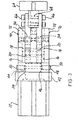
- a clamping apparatus 10 is operably engageable with a linear reciprocal actuator 12 moveable between an extended position illustrated in Fig. 2 and a retracted position illustrated in Fig. 1.
- a hollow housing 14 has a guide track 16 defined on opposing inner surfaces of the hollow housing 14.
- a slide block 18, best seen in Fig. 4 and Fig. 9, is operably engageable with the guide track 16.
- the slide block 18 is capable of being driven, moved, and positioned along the guide track 16 by the actuator 12 between first and second end limits of movement corresponding to the retracted and extended positions respectably of the actuator 12.
- a cam 20 is connected to or carried by the slide block 18 for movement along the guide track 16.
- the cam 20 is operably connected to the actuator 12 for movement along the guide track 16 in response to movement of the actuator between the retracted and extended positions.
- At least one pivoting arm 22 is pivotably mounted for rotation about a pivot axis with respect to the housing 14.
- the pivot axis of each pivoting arm is disposed adjacent to and spaced from the pivot axis.
- Each pivoting arm 22 has an elongate slot 24 disposed adjacent to and spaced from the pivot axis.
- the cam 20 is positioned within the elongate slot 24 of each pivoting arm 22 for converting linear reciprocal movement of the cam 20 into pivoting rotation of each pivoting arm 22.
- Each pivoting arm 22 is in a clamped position when the slide block 18 or cam 20 is in the first end limit of movement as illustrated in Fig. 1, and each pivoting arm 22 is in a released position when the slide block 18 or cam 20 is in the second end limit as illustrated in Fig. 2.
- each pivoting arm 22 is defined by two arcuate surfaces 26 and 28 extending parallel to one another with two end surfaces 30 and 32 joining the arcuate surfaces 26 and 28 to one another to define a closed loop surface.
- the arcuate surfaces 26 and 28 define convex arcuate segments with respect to the pivot axis of each pivoting arm 22.
- each pivoting arm 22 is connected to the housing through a pivot pin 34 defining the pivot axis.
- the elongate slot 24 extends convex with respect to the pivot axis of the pivot pin 34 having a first end surface 30 closest to the pivot pin 34 and a second end surface 32 furthest from the pivot pin 34.
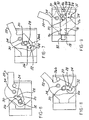
- Fig. 9 illustrates the pivoting arm 22 in the fully open or released position.
- At least one pivot pin 34 is supported from the housing 14 for connection through each pivoting arm 22.
- Each pivoting arm 22 is pivotal about the pivot axis to define a potential range of arm motion from the clamped position illustrated in Fig. 6 to the fully released position illustrated in Fig. 9.
- An optional stop projection 36 can be supported from the housing 14 for obstructing or abbreviating the range of arm motion in selective positions to define selectable positions between the clamped position of Fig. 6 and the released position of Fig. 9.
- a first stop projection 36a is illustrated in Fig. 7 to restrict further arm motion toward the released position beyond that illustrated.
- the cam 20 is stopped at a position spaced from the first end surface 30 when using the optional first stop projection 36a as illustrated in Fig. 7. If a greater range of arm motion is required, the optional stop projection 36 can be positioned as illustrated at 36b in Fig. 8. The position of stop projection 36b permits further opening movement of each pivoting arm 22 to a position of approximately 45° with respect to the clamped position. As illustrated in Fig. 8, the cam 20 is permitted to move closer to the first end surface 30 than that permitted in the configuration illustrated in Fig.
- the present invention can include a swivel joint 38 for supporting the housing 14 in any angular orientation with respect to the actuator 12.
- the swivel joint 38 is connected to or carried by the actuator 12 or mounting bracket 40.
- the snivel oint 38 includes a plate 42 or portion of the mounting bracket 40 having a collar 44 extending outwardly from the plate 42.
- the housing 14 includes an aperture 46 complementary in shape to the collar 44 allowing the housing 14 to seat on the collar 44 with the aperture 46 substantially surrounding the collar 44.
- Fastener means 48 is provided for securing the housing 14 on the collar 44 of the swivel joint 38.
- the fastener means 48 can include one or more set screws 50 or any other suitable fastener.
- the swivel joint 38 permits the housing to be seated and secured with respect to the collar 44 in any desired angular orientation with respect to a longitudinal axis of the linear reciprocal actuator 12.
- the mounting bracket 40 can include means 52 for supporting the clamping apparatus 10 with respect to a support structure.
- the supporting means 52 can be mounted on the plate 42 or form a portion of the mounting bracket 40.
- the supporting means 52 can include a ball or semi-spherical collar 54 engageable with, carried by or connected to the support structure (not shown).
- the outer periphery of the ball or semi-spherical collar 54 is adjustably engaged between two portions of a split ring 56 and 58 respectively.
- the two portions of the split ring 56 and 58 are lockingly engageable with respect to the spherical surface of the ball or semi-spherical collar 54 when driven toward engagement with one another by a suitable fastener, such as bolt 60 engaging within threaded aperture 62.
- any suitable configuration of fingers 64 can be connected to the outer end of each pivoting arm 22 to provide the desired gripper jaw or end treatment.
- the selected set of complementary fingers 64 can be connected to the outer ends of each pivoting arm 22 by any appropriate fasteners, such as by way of example and not limitation, bolts 66 threadably engaged within threaded apertures 68.
- the encasing means 70 can include a side plate or cover 72 for substantially enclosing the pivoting arm 22 with respect to the housing 14.
- the side plate or cover 72 is connected to the far side of the housing 14 while the side plate or cover 72 on the near side of the housing 14 has been removed to show the internal structure of the pivoting arm 22, cam 20 and the outer portion of slide block 18.
- the side plate 72 can be reconnected to the housing 14 by any suitable means, such as threaded fasteners connecting to the inner portion of the housing 14 or through the end plate 74 into the side plate 72.
- the encasing means 70 attaches to the housing 14 and serves to protect the elongate slot and cam from contamination or foreign matter that can be present in industrial production environments.
- the internal portion of the housing 14 includes first and second opposing surfaces 76 and 78 defining a longitudinally extending slot 80 within the hollow housing 14.
- the longitudinally extending slot 80 operably receives the inner portion of slide block 18 best seen in Fig. 9.
- the cam 20 extends outwardly from the inner portion of the slide block 18 to the outer portion of the slide block 18 after passing through the elongate slot 24 of the pivoting arm 22 as best seen in Fig. 4.
- the inner portion of the slide block 18 includes an adapter 82, best seen in Fig.
- the inner portion of the slide block 18 also includes a stop-engaging surface 84.
- An adjustable stop 86 is threadably engaged through the aperture 88 formed in the inner portion of the housing 14 best seen in Figs. 5 and 9.
- the adjustable stop member 86 can be threadably adjusted with respect to the hollow interior of the housing 14 for abbreviating a permissible range of motion for the cam 20 along the guide track 16.
- the guide track 16 defines the permissible range of motion for the slide block 18 and cam 20.
- the abbreviating means 90 such as adjustable stop member 86, can partially limit the range of arm motion by adjusting the stop member 86 to further encroach on the end portion of the guide track 16 thereby preventing the slide block 18 from reaching the fully extended position of the actuator 12.
- a clamping apparatus 10 can also include a second arm portion 92 hingedly connected to the pivoting arm 22 with pivot pin 94.
- a lost-motion link 96 is pivotally mounted with respect to the housing 14 for rotational movement about pin 98.
- the lost-motion link 96 also includes an elongate slot 100 for operably receiving a portion of the cam 20 carried by the slide block 18.
- the second arm portion 92 includes a linear slot 102.
- a second cam 104 is connected to or carried by the lost-motion link 96 adjacent an end opposite from the elongate slot 100.
- the second cam 104 operably engages within the linear slot 102 of the second arm portion 92 for moving the second arm portion 92 in response to movement of the cam 20 within the first elongate slot 24 of the pivoting arm 22 and the second elongate slot 100 of the lost-motion link 96.
- the lost-motion link 96 is rotatably attached to the housing 14.
- the lost-motion link has a curved slot 100 for receiving the cam 20 to move the pivoting second arm portion 92 of the pivoting arm 22 between the clamped position and the released position as the cam 20 is moved within the elongate slot 24 and the curved slot 100 in response to movement of the slide block 18 along the guide track 16.
- the cam 20 is positioned within the first and second elongate slots 24 and 100 for converting linear reciprocal movement of the cam into pivoting rotation of the pivoting arm 22 and second arm portion 92.
- the second arm portion 92 of the pivoting arm 22 is in the clamped position, illustrated in Fig. 10, when the cam 20 and slide block 18 are in the first end limit of movement or retracted position of the linear reciprocal actuator.
- the second arm portion 92 of the pivoting arm 22 is in a released position, illustrated in Fig. 11, when the slide block 18 and cam 20 are in the second end limit of movement corresponding to the extended position of the linear reciprocal actuator.
Landscapes
- Engineering & Computer Science (AREA)
- Mechanical Engineering (AREA)
- Jigs For Machine Tools (AREA)
- Transmission Devices (AREA)
- Manipulator (AREA)
Claims (11)
- Eine Spannvorrichtung umfassend:ein, entlang einem Bewegungsweg zwischen einer ausgefahrenen und einer eingefahrenen Stellung bewegliches lineares Reziprokbetätigungsglied (12);ein hohles Gehäuse (14), das eine auf gegenüberliegenden inneren Oberflächen definierte Führungsspur (16) aufweist;ein mit besagter Führungsspur (16) betriebsfähig koppelbarer Gleitblock (18), der entlang besagter Führungsspur (16) zwischen ersten und zweiten Bewegungsendbegrenzung entsprechend den besagten jeweils eingefahrenen und ausgefahrenen Positionen des besagten Betätigungsglieds (12) angetrieben, bewegt und positioniert werden kann;ein mit besagtem Gleitblock (18) verbundenes Nockenmittel (20), das dazu bestimmt ist, sich zusammen mit dem besagten Gleitblock zu bewegen, undmindestens ein Schwenkarm (22), wobei jeder besagte Schwenkarm (22) schwenkbar montiert ist, um sich um eine Schwenkachse (34) in Bezug auf besagtes, an besagte Führungsspur (16) angrenzendes Gehäuse (14) zu drehen, und wobei jeder besagte Schwenkarm (22) einen zu besagter Schwenkachse (34) benachbarten und von ihr beabstandeten länglichen Schlitz (24) aufweist, wobei besagte Nocke (20) in besagtem länglichen Schlitz (24) von jedem besagten Schwenkarm (22) zur Umwandlung der linearen Reziprokbewegung besagter Nocke in eine Schwenkrotation von jedem besagten Schwenkarm (22) positioniert wird, während besagter Gleitblock entlang besagter Führungsspur bewegt wird;wobei das Nockenmittel (20) ein einziges Nockenelement (20) umfasst, das in besagtem länglichen Schlitz von jedem besagten Schwenkarm (22) koppelbar ist;worin der längliche Schlitz eine in Bezug auf besagte Schwenkachse (34) konvexe bogenförmige Form aufweist und jeder besagte Schwenkarm (22) sich in Spannstellung befindet, wenn besagter Gleitblock (18) sich in erster Bewegungsendbegrenzung befindet, wobei besagtes Nockenmittel (20) zum Schlitzende (24) benachbart, am weitesten von der Schwenkachse (34) angeordnet ist und wobei jeder besagte Schwenkarm (22) sich in freigabestellung befindet, wenn besagter Gleitblock (18) sich in besagter zweiter Bewegungsendbegrenzung befindet, wobei besagtes Nockenmittel (20) in der Nähe des Schlitzendes (24) am nächsten an der Schwenkachse (34) angeordnet ist.
- Eine Spannvorrichtung nach Patentanspruch 1, worin besagter länglicher Schlitz (24) von jedem besagten Schwenkarm (22) durch zwei bogenförmige, sich parallel zueinander mit zwei, die besagten bogenförmigen Oberflächen (26, 28) miteinander zur Definierung einer geschlossenen Schleife verbindenden Endoberflächen (30, 32) erstreckenden Oberflächen (26, 28) definiert ist, wobei die besagten bogenförmigen Oberflächen (26, 28) durch in Bezug auf die besagte Schwenkachse konvexe bogenförmige Segmente definiert sind.
- Eine Spannvorrichtung nach Patentanspruch 1, umfassend außerdem mindestens einen von besagtem Gehäuse (14) zur Verbindung durch jeden besagten Schwenkarm (22) gehaltenen Schwenkstift (34), wobei jeder besagte, um besagte Schwenkachse drchbarer Schwenkarm (22) eine Armbewegungsspanne definiert; und eine von besagtem Gehäuse (14) tragbare Arretierauskragung (36, 36a, 36b) zur Blockierung der besagten Armbewegungsspanne in ausgewählten Stellungen, um auswählbare Stellungen zwischen der besagten Spannstellung und der besagten Freigabestellung zu definieren.
- Eine Spannvorrichtung mit einem Drehgelenk (38), um besagtes Gehäuse (14) in jeder beliebigen Winkelausrichtung in Bezug auf das besagte Betätigungsglied (12) zu halten und nach irgendeinem der Patentansprüche 1 bis 3, worin besagtes Drehgelenk umfasst: eine Platte (42), eine Schelle (44), auf der Platte (42) befestigt, wobei besagtes Gehäuse (14) eine Öffnung (46) hat, die formkomplementär zu besagter Schelle (44) ist, so dass besagtes Gehäuse (14) auf besagter Schelle (44) sitzt, wobei die besagte Öffnung (46) im wesentlichen die besagte Schelle (44) umgibt, Mittel zur Befestigung des besagten Gehäuses (14) auf besagter Schelle des besagten Drehgelenks, wobei es die besagte Schelle dem besagten Gehäuse (14) ermöglicht, in Bezug auf die besagte Schelle in jeder beliebigen gewünschten Winkelausrichtung in Bezug auf eine Längsachse des besagten Betätigungsglieds (12) zu sitzen und befestigt zu werden.
- Eine Spannvorrichtung nach Patentanspruch 4, umfassend außerdem ein Mittel (52) zum Halten besagten Drehgelenks (38) in Bezug auf eine Haltestruktur, wobei das besagte Haltemittel auf besagter Platte (42) des besagten Drehgelenks angebracht ist.
- Eine Spannvorrichtung nach irgendeinem der Patentansprüche 1 bis 5, umfassend außerdem ein Mittel (86), um eine zulässige Bewegungsspanne für besagte Nocke (20) entlang besagter Führungsspur (16) abzukürzen, worin besagte Führungsspur besagte zulässige Bewegungsspanne für besagten Gleitbock (18) und besagte Nocke definiert, wobei das besagte Abkürzungsmittel in besagtes Gehäuse (14) integriert ist, wobei jeder besagte Schwenkarm (22) um besagte Schwenkachse schwenkt und dabei eine Armbewegungsspanne definiert, wobei besagte Armbewegungsspanne teilweise durch das besagte Abkürzungsmittel (86) begrenzt ist.
- Eine Spannvorrichtung nach irgendeinem der Patentansprüche 1 bis 6, umfassend außerdem ein Mittel (70) zum Einhüllen des besagten länglichen Schlitzes (24) von jedem besagten Schwenkarm (22) und besagter Nocke (20), wobei besagtes Umhüllungsmittel am besagten Gehäuse (14) befestigt ist und dazu dient, besagten länglichen Schlitz und besagte Nocke vor Verschmutzung zu schützen.
- Eine Spannvorrichtung nach irgendeinem der Patentansprüche 1 bis 7, umfassend außerdem jeden besagten Schwenkarm (22) mit einem besagten, dem besagten länglichen Schlitz (24) gegenüberliegenden, gelenkig verbundenen artikulierten Teil (92); und eine Leerlaufverbindung (96), die schwenkbar an voneinander entfernten Orten an besagtem Gehäuse (14) und besagtem artikulierten Teil befestigt ist, wobei besagte Lecrlaufverbindung einen gekrümmten Schlitz (100) zur Aufnahme der besagten Nocke (20) aufweist, um den besagten artikulierten Teil des besagten Schwenkarms zwischen einer Spannstellung und einer Freigabestellung zu bewegen, während besagte Nocke simultan in besagtem länglichen Schlitz und besagtem bogenförmigen Schlitz in Antwort auf die Bewegung des besagten Gleitblocks (18) entlang besagter Führungsspur (16) bewegt wird.
- Eine Spannvorrichtung nach irgendeinem der Patentansprüche 1 bis 8, worin besagte Spannstellung durch besagte, in besagtem länglichen Schlitz (24) positionierte Nocke definiert ist, so dass besagte Nocke in einer Maximalentfernung von besagter Drehachse angeordnet ist.
- Eine Spannvorrichtung nach irgendeinem der Patentansprüche 1 bis 9, worin besagter Schwenkarm (22) zwischen besagter Spannstellung und besagter Freigabestellung bewegt wird, während besagter Gleitblock (18) entlang besagter Führungsspur und besagte Nocke simultan in besagtem länglichen Schlitz (24) bewegt werden.
- Eine Spannvorrichtung nach irgendeinem der Patentansprüche 1 bis 10, umfassend außerdem einen auf besagtem Gehäuse anbringbaren Betätigungsglied.
Applications Claiming Priority (2)
| Application Number | Priority Date | Filing Date | Title |
|---|---|---|---|
| US3927 | 1998-01-07 | ||
| US09/003,927 US6079896A (en) | 1998-01-07 | 1998-01-07 | Clamp with improved internal cam action |
Publications (3)
| Publication Number | Publication Date |
|---|---|
| EP0928663A2 EP0928663A2 (de) | 1999-07-14 |
| EP0928663A3 EP0928663A3 (de) | 2001-03-28 |
| EP0928663B1 true EP0928663B1 (de) | 2006-11-15 |
Family
ID=21708267
Family Applications (1)
| Application Number | Title | Priority Date | Filing Date |
|---|---|---|---|
| EP99300049A Revoked EP0928663B1 (de) | 1998-01-07 | 1999-01-05 | Spannvorrichtung mit interner Nockenwirkung |
Country Status (4)
| Country | Link |
|---|---|
| US (3) | US6079896A (de) |
| EP (1) | EP0928663B1 (de) |
| DE (1) | DE69933952T2 (de) |
| ES (1) | ES2277410T3 (de) |
Cited By (1)
| Publication number | Priority date | Publication date | Assignee | Title |
|---|---|---|---|---|
| US8136803B2 (en) | 2007-01-15 | 2012-03-20 | Phd, Inc. | Armover clamp assembly |
Families Citing this family (49)
| Publication number | Priority date | Publication date | Assignee | Title |
|---|---|---|---|---|
| US6874834B2 (en) | 1996-10-07 | 2005-04-05 | Phd, Inc. | Linear slide gripper |
| US7021687B2 (en) * | 1998-08-04 | 2006-04-04 | Phd, Inc. | Clamp assembly |
| US6141719A (en) * | 1998-12-10 | 2000-10-31 | Network Technologies, Inc. | USB selector switch |
| GB2359512B (en) * | 1999-11-26 | 2004-01-21 | Hmc Brauer Ltd | Power clamps |
| US6361095B1 (en) | 2000-06-29 | 2002-03-26 | Delaware Capital Formation, Inc. | Adjustable stroke gripper assembly |
| DE10124063A1 (de) * | 2001-05-16 | 2002-11-28 | Sta Co Mettallerzeugnisse Gmbh | Spannvorrichtung zum gegenseitigen Festspannen insbesondere von per Laser zu verschweißenden Karosserieteilrändern |
| EP1264663A3 (de) * | 2001-06-05 | 2004-05-12 | PHD, Inc. | Spannvorrichtung |
| DE10138786C1 (de) * | 2001-08-07 | 2002-10-31 | Benteler Automobiltechnik Gmbh | Vorrichtung zur Lagefixierung eines Werkstücks an einer Werkstückaufnahme |
| US6666489B2 (en) * | 2001-08-23 | 2003-12-23 | Btm Corporation | Sealed gripper apparatus |
| US6902160B1 (en) * | 2003-01-22 | 2005-06-07 | Zaytran, Inc. | Locating pin with integrated clamp |
| US6931980B1 (en) * | 2003-03-21 | 2005-08-23 | Zaytran, Inc. | Pneumatic device with cushioning mechanism |
| DE20315264U1 (de) * | 2003-10-04 | 2005-02-17 | Staudinger Forschungs- Und Entwicklungs Gmbh & Co. Kg | Spannvorrichtung |
| WO2005049260A1 (es) * | 2003-11-24 | 2005-06-02 | Misati, S.L. | Brida para instalaciones de soldadura automatizadas |
| US7185798B2 (en) * | 2004-04-22 | 2007-03-06 | Mpr Associates, Inc. | Apparatus and method for mechanically reinforcing the welds between riser pipes and riser braces in boiling water reactors |
| ITMI20042003A1 (it) * | 2004-10-21 | 2005-01-21 | Univer Spa | "dispositivo di presa per pezzi da lavorare per sistemi robotizzati di manipolazione" |
| ITMI20050087U1 (it) * | 2005-03-17 | 2006-09-18 | Univer Spa | Dispositivo di bloccaggio per pezzi da lavorare con organo di bloccaggio a forma di gancio |
| JP4831475B2 (ja) * | 2006-04-14 | 2011-12-07 | 新東工業株式会社 | 治具パレット |
| US7837247B2 (en) * | 2006-07-18 | 2010-11-23 | Syron Engineering & Manufacturing, Llc | Gripper with central support |
| DE102006049447A1 (de) * | 2006-10-17 | 2008-01-10 | De-Sta-Co Europe Gmbh | Spannvorrichtung |
| US7845698B2 (en) * | 2007-03-05 | 2010-12-07 | Syron Engineering & Manufacturing, Llc | Gripper with adjustable bumper stops |
| US20080237957A1 (en) * | 2007-03-27 | 2008-10-02 | Conrad Earl Waldorf | Adjustable stroke gripper |
| US20090033013A1 (en) * | 2007-07-31 | 2009-02-05 | Vought Aircraft Industries, Inc. | Multi-piece automated fiber placement mandrel automated clamping and indexing system |
| DE102007050353B4 (de) * | 2007-10-10 | 2014-07-10 | Schunk Gmbh & Co. Kg Spann- Und Greiftechnik | Greifvorrichtung |
| IL196572A (en) * | 2008-02-04 | 2013-02-28 | Erowa Ag | Workpiece clamping fixture |
| US8176616B2 (en) * | 2008-12-29 | 2012-05-15 | GM Global Technology Operations LLC | Method for error-proofing a reconfigurable clamp |
| DE102009009944B4 (de) * | 2009-02-20 | 2011-02-24 | Terex-Demag Gmbh | Sicherungs- und Verbolzungseinheit |
| US8595911B2 (en) * | 2010-03-30 | 2013-12-03 | Honda Motor Co., Ltd. | Extraction device for removing a vehicle fastener |
| DE102011100965B4 (de) * | 2011-05-09 | 2013-02-28 | Viega Gmbh & Co. Kg | Pressbacke und Verfahren zum Herstellen einer Pressverbindung |
| DE102012108087A1 (de) * | 2012-08-31 | 2014-05-28 | Krones Ag | Greifeinrichtung zum Greifen von Behältnissen |
| CN104669240A (zh) * | 2013-11-30 | 2015-06-03 | 深圳富泰宏精密工业有限公司 | 装夹机构 |
| MX388543B (es) * | 2014-03-06 | 2025-03-20 | Hubbell Inc | Sistema sujetador de molde, de accionamiento eléctrico, para soldeo por reacción exotérmica. |
| EP2921260B1 (de) | 2014-03-20 | 2016-08-31 | UNIVER S.p.A. | Pneumatisch betreibbares Arbeitsgerät |
| US9975252B2 (en) * | 2014-09-19 | 2018-05-22 | Delaware Capital Formation, Inc. | Gripper |
| US9906093B2 (en) | 2014-10-31 | 2018-02-27 | Delaware Capital Formation, Inc. | Universal housing mount |
| JP6355054B2 (ja) * | 2015-04-24 | 2018-07-11 | Smc株式会社 | クランプ装置 |
| US10011025B2 (en) * | 2015-06-10 | 2018-07-03 | Phd, Inc. | Articulating gripper tooling |
| US10689240B1 (en) | 2017-06-07 | 2020-06-23 | Cornelius, Inc. | Automated beverage dispensing machines |
| JP6939196B2 (ja) * | 2017-07-27 | 2021-09-22 | 日本精工株式会社 | 把持装置 |
| US10549431B2 (en) | 2018-06-15 | 2020-02-04 | Delaware Capital Formation, Inc. | Gripper with a trident body section |
| US10994423B2 (en) | 2018-06-15 | 2021-05-04 | Delaware Capital Formation, Inc. | Gripper with a trident body section |
| DE102019006711B4 (de) * | 2019-09-25 | 2021-06-10 | Günther Zimmer | Greifeinheitsmodul mit Schwenkschubgelenk |
| US11452297B2 (en) * | 2020-06-25 | 2022-09-27 | Tracy Brian Hare | Robot gripper |
| US20240315263A1 (en) * | 2020-06-25 | 2024-09-26 | Tracy Brian Hare | Robot gripper |
| US11345050B2 (en) | 2020-10-20 | 2022-05-31 | Phd, Inc. | Articulating gripper tooling |
| CN112171603A (zh) * | 2020-11-12 | 2021-01-05 | 安徽得高金属制品有限公司 | 一种薄壁三通管夹紧设备 |
| US12178667B2 (en) | 2021-02-16 | 2024-12-31 | Mako Surgical Corp. | Clamp assembly for fixing a navigation tracker to a portion of bone |
| KR102266527B1 (ko) * | 2021-03-15 | 2021-06-18 | 유윤상 | 표면 처리용 기판 클램핑 장치 |
| US11633865B2 (en) * | 2021-04-01 | 2023-04-25 | Ford Global Technologies, Llc | Mechanically actuated end of arm tooling device |
| US20250011084A1 (en) * | 2023-07-06 | 2025-01-09 | Intelligrated Headquarters, Llc | Load handling systems and methods of use |
Family Cites Families (38)
| Publication number | Priority date | Publication date | Assignee | Title |
|---|---|---|---|---|
| US886003A (en) * | 1907-08-08 | 1908-04-28 | Howard Wattles V | Gaff-hook. |
| US3482830A (en) * | 1966-04-05 | 1969-12-09 | Jack J Sendoykas | Clamp |
| US3570835A (en) * | 1968-10-08 | 1971-03-16 | Dover Corp | Power operated clamping device |
| US3599957A (en) * | 1969-04-28 | 1971-08-17 | Leland F Blatt | Cam wedge power swing away with guided arm |
| US3698757A (en) | 1969-08-04 | 1972-10-17 | British Steel Corp | Lifting tongs |
| US3724837A (en) * | 1970-09-02 | 1973-04-03 | Dover Corp | Retracting clamp |
| US3807719A (en) * | 1972-01-06 | 1974-04-30 | R Williamson | Clamp |
| US3817510A (en) * | 1973-01-10 | 1974-06-18 | J Jatcko | Cam wedge swivel gripper head |
| GB1456703A (en) | 1973-03-26 | 1976-11-24 | Dresser Ind | Gripper for pipe handling apparatus machine for spi |
| DE2904378C2 (de) | 1979-02-06 | 1983-04-28 | ASEA AB, 72183 Västeraas | Zangengreifarm zum Stützen und Greifen langer zylindrischer Werkstücke an Werkzeugmaschinen |
| DE2937061C2 (de) | 1979-09-13 | 1981-11-12 | Pfaff Industriemaschinen Gmbh, 6750 Kaiserslautern | Handhabungsgerät mit einer Greifvorrichtung |
| US4475607A (en) | 1981-12-11 | 1984-10-09 | Walker-Neer Manufacturing Co. Inc. | Clamp and insert for clamping drilling tubulars |
| US4494739A (en) * | 1983-03-04 | 1985-01-22 | State Die & Engineering, Inc. | Power operated rotatable clamping assembly |
| US4529182A (en) * | 1983-04-11 | 1985-07-16 | State Die & Engineering, Inc. | Wide opening gripping jaw assembly |
| SU1187981A1 (ru) * | 1984-07-12 | 1985-10-30 | Марийский Ордена Дружбы Народов Политехнический Институт Им.М.Горького | Схват |
| DE3528337A1 (de) * | 1985-08-07 | 1987-02-19 | Eugen Rapp | Spannvorrichtung |
| US4793602A (en) * | 1987-10-26 | 1988-12-27 | De-Sta-Co Division, Dover Resources, Inc. | Locking power clamp |
| FR2630595B1 (fr) | 1988-04-26 | 1990-08-24 | Roudaut Philippe | Pince electrique a maintien magnetique |
| US5064177A (en) * | 1990-01-16 | 1991-11-12 | Delaware Capital Formation | Power clamp with enclosed track |
| DE4003201C2 (de) * | 1990-02-03 | 1995-04-27 | Dango & Dienenthal Maschbau | Schnellkupplungsvorrichtung für Schmiede- und Transportmanipulatoren |
| US5085480A (en) | 1990-04-09 | 1992-02-04 | Jackson Donald T | Cam operated workpiece engaging apparatus |
| FR2660917B1 (fr) | 1990-04-11 | 1992-11-20 | Perrier Rene | Pince de prehension et machine de traitement d'objets, notamment de bouteilles, ainsi equipee. |
| US5152568A (en) * | 1991-01-24 | 1992-10-06 | Blatt John A | Extendible gripper |
| FR2679480B1 (fr) * | 1991-07-26 | 1993-10-15 | Roudaut Philippe | Pince pneumatique. |
| US5193789A (en) | 1992-02-12 | 1993-03-16 | Avco Corporation | Automatic clamping apparatus |
| US5215295A (en) * | 1992-06-29 | 1993-06-01 | Delaware Capital Formation | Enclosed rotatable head power clamp |
| DE4236670A1 (de) * | 1992-10-30 | 1994-05-05 | Sta Co Mettallerzeugnisse Gmbh | Klemmspannvorrichtung |
| CA2152666C (en) | 1993-01-25 | 2004-01-27 | Hugo Dries | Container gripper apparatus |
| US5284375A (en) | 1993-03-12 | 1994-02-08 | Ingersoll-Rand Company | Single actuation rod gripping mechanism |
| US5516173A (en) | 1993-03-15 | 1996-05-14 | Btm Corporation | Gripper |
| US5460358A (en) * | 1993-11-29 | 1995-10-24 | Sendoykas; Jack J. | Power clamp |
| US5975605A (en) * | 1994-11-14 | 1999-11-02 | Kot; Norbert J | Enclosed clamping or gripping device with accessible load controlling spring |
| US6115898A (en) | 1995-06-06 | 2000-09-12 | Btm Corporation | Force multiplying apparatus for clamping a workpiece and forming a joint therein |
| US5687961A (en) * | 1995-11-30 | 1997-11-18 | Aladdin Engineering & Manufacturing, Inc. | Fluid operated clamp including integral frame and slide member support |
| US5967502A (en) * | 1996-09-04 | 1999-10-19 | Delaware Capital Formation, Inc. | Enclosed pneumatic clamp |
| JP3749315B2 (ja) | 1996-09-06 | 2006-02-22 | Smc株式会社 | チャック装置 |
| EP0935516B1 (de) | 1996-10-07 | 2004-01-21 | PHD, Inc. | Modulare stanzteilübertragungseinrichtung |
| US7021687B2 (en) * | 1998-08-04 | 2006-04-04 | Phd, Inc. | Clamp assembly |
-
1998
- 1998-01-07 US US09/003,927 patent/US6079896A/en not_active Ceased
-
1999
- 1999-01-05 DE DE69933952T patent/DE69933952T2/de not_active Expired - Lifetime
- 1999-01-05 EP EP99300049A patent/EP0928663B1/de not_active Revoked
- 1999-01-05 ES ES99300049T patent/ES2277410T3/es not_active Expired - Lifetime
-
2002
- 2002-05-23 US US10/154,368 patent/USRE39786E1/en not_active Expired - Lifetime
-
2005
- 2005-08-03 US US11/196,844 patent/USRE41223E1/en not_active Expired - Lifetime
Cited By (1)
| Publication number | Priority date | Publication date | Assignee | Title |
|---|---|---|---|---|
| US8136803B2 (en) | 2007-01-15 | 2012-03-20 | Phd, Inc. | Armover clamp assembly |
Also Published As
| Publication number | Publication date |
|---|---|
| DE69933952D1 (de) | 2006-12-28 |
| DE69933952T2 (de) | 2007-10-31 |
| EP0928663A3 (de) | 2001-03-28 |
| ES2277410T3 (es) | 2007-07-01 |
| USRE41223E1 (en) | 2010-04-13 |
| US6079896A (en) | 2000-06-27 |
| USRE39786E1 (en) | 2007-08-21 |
| EP0928663A2 (de) | 1999-07-14 |
Similar Documents
| Publication | Publication Date | Title |
|---|---|---|
| EP0928663B1 (de) | Spannvorrichtung mit interner Nockenwirkung | |
| CN1041389C (zh) | 具有轴向夹紧作用的锁紧钳 | |
| KR0136248B1 (ko) | 한장 또는 여러장의 인쇄물을 이송하는 이송 장치용 집게 | |
| CA2699293C (en) | Gimbal assembly for tool support | |
| US5299847A (en) | Gripper assembly | |
| US4905973A (en) | Power operated clamp with externally mounted adjustable clamp arm | |
| CN1047338C (zh) | 具有倾斜螺杆的夹具 | |
| HUT69237A (en) | Clamp with screw | |
| US6042166A (en) | Gripper | |
| US6056281A (en) | Adjustable stoppers and mounting assemblies for parts grippers | |
| CA2226817A1 (en) | Universal gripper | |
| CN1730191A (zh) | 设有用于夹持被弯折细长工件的夹具的折弯机模具 | |
| CA2089821A1 (en) | Gripper for a conveying device for conveying single-sheet or multiple-sheet printed products | |
| US6565074B1 (en) | Rotary clamp having an adjustable pre-stop | |
| US6948708B2 (en) | Gripper provided with an adjustable sensor assembly | |
| JP2000512217A (ja) | 工作物保持台のための急速据付および解放作動装置 | |
| US7104512B2 (en) | Articulated arm especially for a device for optically capturing objects | |
| US20030222469A1 (en) | Clamp assembly | |
| CN221195630U (zh) | 一种管夹 | |
| EP1524081A3 (de) | Steuereinheit für die Steuerung der Endposition eines drehenden Spannarms einer Spanneinrichtung mit einem Gelenkhebel | |
| EP1649968A2 (de) | Einrichtung zum Greifen eines Werkstückes für roboterartige Handhabungssyteme | |
| JP3980553B2 (ja) | 方向転換装置 | |
| KR20090082174A (ko) | 구성 요소 위치 설정용 장치 | |
| US6453715B1 (en) | Gripping device for straightening a car body | |
| JPH0225736B2 (de) |
Legal Events
| Date | Code | Title | Description |
|---|---|---|---|
| PUAI | Public reference made under article 153(3) epc to a published international application that has entered the european phase |
Free format text: ORIGINAL CODE: 0009012 |
|
| AK | Designated contracting states |
Kind code of ref document: A2 Designated state(s): BE CH DE DK ES FR GB IE IT LI SE |
|
| AX | Request for extension of the european patent |
Free format text: AL;LT;LV;MK;RO;SI |
|
| PUAL | Search report despatched |
Free format text: ORIGINAL CODE: 0009013 |
|
| AK | Designated contracting states |
Kind code of ref document: A3 Designated state(s): AT BE CH CY DE DK ES FI FR GB GR IE IT LI LU MC NL PT SE |
|
| AX | Request for extension of the european patent |
Free format text: AL;LT;LV;MK;RO;SI |
|
| 17P | Request for examination filed |
Effective date: 20010627 |
|
| RAP1 | Party data changed (applicant data changed or rights of an application transferred) |
Owner name: NORGREN AUTOMOTIVE INC. |
|
| AKX | Designation fees paid |
Free format text: BE CH DE DK ES FR GB IE IT LI SE |
|
| 17Q | First examination report despatched |
Effective date: 20030915 |
|
| REG | Reference to a national code |
Ref country code: SE Ref legal event code: TRGR |
|
| GRAP | Despatch of communication of intention to grant a patent |
Free format text: ORIGINAL CODE: EPIDOSNIGR1 |
|
| GRAS | Grant fee paid |
Free format text: ORIGINAL CODE: EPIDOSNIGR3 |
|
| GRAA | (expected) grant |
Free format text: ORIGINAL CODE: 0009210 |
|
| AK | Designated contracting states |
Kind code of ref document: B1 Designated state(s): BE CH DE DK ES FR GB IE IT LI SE |
|
| PG25 | Lapsed in a contracting state [announced via postgrant information from national office to epo] |
Ref country code: LI Free format text: LAPSE BECAUSE OF FAILURE TO SUBMIT A TRANSLATION OF THE DESCRIPTION OR TO PAY THE FEE WITHIN THE PRESCRIBED TIME-LIMIT Effective date: 20061115 Ref country code: CH Free format text: LAPSE BECAUSE OF FAILURE TO SUBMIT A TRANSLATION OF THE DESCRIPTION OR TO PAY THE FEE WITHIN THE PRESCRIBED TIME-LIMIT Effective date: 20061115 Ref country code: BE Free format text: LAPSE BECAUSE OF FAILURE TO SUBMIT A TRANSLATION OF THE DESCRIPTION OR TO PAY THE FEE WITHIN THE PRESCRIBED TIME-LIMIT Effective date: 20061115 |
|
| REG | Reference to a national code |
Ref country code: GB Ref legal event code: FG4D |
|
| REG | Reference to a national code |
Ref country code: CH Ref legal event code: EP |
|
| REF | Corresponds to: |
Ref document number: 69933952 Country of ref document: DE Date of ref document: 20061228 Kind code of ref document: P |
|
| REG | Reference to a national code |
Ref country code: IE Ref legal event code: FG4D |
|
| PG25 | Lapsed in a contracting state [announced via postgrant information from national office to epo] |
Ref country code: IE Free format text: LAPSE BECAUSE OF NON-PAYMENT OF DUE FEES Effective date: 20070105 |
|
| PG25 | Lapsed in a contracting state [announced via postgrant information from national office to epo] |
Ref country code: DK Free format text: LAPSE BECAUSE OF FAILURE TO SUBMIT A TRANSLATION OF THE DESCRIPTION OR TO PAY THE FEE WITHIN THE PRESCRIBED TIME-LIMIT Effective date: 20070215 |
|
| REG | Reference to a national code |
Ref country code: CH Ref legal event code: PL |
|
| ET | Fr: translation filed | ||
| REG | Reference to a national code |
Ref country code: ES Ref legal event code: FG2A Ref document number: 2277410 Country of ref document: ES Kind code of ref document: T3 |
|
| PLBI | Opposition filed |
Free format text: ORIGINAL CODE: 0009260 |
|
| PLAX | Notice of opposition and request to file observation + time limit sent |
Free format text: ORIGINAL CODE: EPIDOSNOBS2 |
|
| 26 | Opposition filed |
Opponent name: PHD, INC. Effective date: 20070815 |
|
| PLAF | Information modified related to communication of a notice of opposition and request to file observations + time limit |
Free format text: ORIGINAL CODE: EPIDOSCOBS2 |
|
| PLAB | Opposition data, opponent's data or that of the opponent's representative modified |
Free format text: ORIGINAL CODE: 0009299OPPO |
|
| R26 | Opposition filed (corrected) |
Opponent name: PHD, INC. Effective date: 20070815 |
|
| PLBB | Reply of patent proprietor to notice(s) of opposition received |
Free format text: ORIGINAL CODE: EPIDOSNOBS3 |
|
| PGFP | Annual fee paid to national office [announced via postgrant information from national office to epo] |
Ref country code: ES Payment date: 20090218 Year of fee payment: 11 |
|
| APBM | Appeal reference recorded |
Free format text: ORIGINAL CODE: EPIDOSNREFNO |
|
| APBP | Date of receipt of notice of appeal recorded |
Free format text: ORIGINAL CODE: EPIDOSNNOA2O |
|
| APAH | Appeal reference modified |
Free format text: ORIGINAL CODE: EPIDOSCREFNO |
|
| PGFP | Annual fee paid to national office [announced via postgrant information from national office to epo] |
Ref country code: GB Payment date: 20090107 Year of fee payment: 11 |
|
| APBQ | Date of receipt of statement of grounds of appeal recorded |
Free format text: ORIGINAL CODE: EPIDOSNNOA3O |
|
| PGFP | Annual fee paid to national office [announced via postgrant information from national office to epo] |
Ref country code: SE Payment date: 20090128 Year of fee payment: 11 Ref country code: IT Payment date: 20090131 Year of fee payment: 11 |
|
| PGFP | Annual fee paid to national office [announced via postgrant information from national office to epo] |
Ref country code: FR Payment date: 20090113 Year of fee payment: 11 |
|
| GBPC | Gb: european patent ceased through non-payment of renewal fee |
Effective date: 20100105 |
|
| EUG | Se: european patent has lapsed | ||
| REG | Reference to a national code |
Ref country code: FR Ref legal event code: ST Effective date: 20100930 |
|
| PG25 | Lapsed in a contracting state [announced via postgrant information from national office to epo] |
Ref country code: FR Free format text: LAPSE BECAUSE OF NON-PAYMENT OF DUE FEES Effective date: 20100201 |
|
| PG25 | Lapsed in a contracting state [announced via postgrant information from national office to epo] |
Ref country code: GB Free format text: LAPSE BECAUSE OF NON-PAYMENT OF DUE FEES Effective date: 20100105 |
|
| REG | Reference to a national code |
Ref country code: ES Ref legal event code: FD2A Effective date: 20110324 |
|
| PG25 | Lapsed in a contracting state [announced via postgrant information from national office to epo] |
Ref country code: IT Free format text: LAPSE BECAUSE OF NON-PAYMENT OF DUE FEES Effective date: 20100105 |
|
| PG25 | Lapsed in a contracting state [announced via postgrant information from national office to epo] |
Ref country code: ES Free format text: LAPSE BECAUSE OF NON-PAYMENT OF DUE FEES Effective date: 20110310 |
|
| PG25 | Lapsed in a contracting state [announced via postgrant information from national office to epo] |
Ref country code: ES Free format text: LAPSE BECAUSE OF NON-PAYMENT OF DUE FEES Effective date: 20100106 |
|
| PGFP | Annual fee paid to national office [announced via postgrant information from national office to epo] |
Ref country code: DE Payment date: 20111229 Year of fee payment: 14 |
|
| REG | Reference to a national code |
Ref country code: DE Ref legal event code: R103 Ref document number: 69933952 Country of ref document: DE Ref country code: DE Ref legal event code: R064 Ref document number: 69933952 Country of ref document: DE |
|
| APBU | Appeal procedure closed |
Free format text: ORIGINAL CODE: EPIDOSNNOA9O |
|
| PG25 | Lapsed in a contracting state [announced via postgrant information from national office to epo] |
Ref country code: SE Free format text: LAPSE BECAUSE OF NON-PAYMENT OF DUE FEES Effective date: 20100106 |
|
| RDAF | Communication despatched that patent is revoked |
Free format text: ORIGINAL CODE: EPIDOSNREV1 |
|
| RDAG | Patent revoked |
Free format text: ORIGINAL CODE: 0009271 |
|
| STAA | Information on the status of an ep patent application or granted ep patent |
Free format text: STATUS: PATENT REVOKED |
|
| 27W | Patent revoked |
Effective date: 20120703 |
|
| REG | Reference to a national code |
Ref country code: DE Ref legal event code: R107 Ref document number: 69933952 Country of ref document: DE Effective date: 20130124 |
|
| REG | Reference to a national code |
Ref country code: SE Ref legal event code: ECNC |