EP0931987B1 - Heizkörperverkleidung - Google Patents
Heizkörperverkleidung Download PDFInfo
- Publication number
- EP0931987B1 EP0931987B1 EP99100151A EP99100151A EP0931987B1 EP 0931987 B1 EP0931987 B1 EP 0931987B1 EP 99100151 A EP99100151 A EP 99100151A EP 99100151 A EP99100151 A EP 99100151A EP 0931987 B1 EP0931987 B1 EP 0931987B1
- Authority
- EP
- European Patent Office
- Prior art keywords
- enclosure part
- radiator
- lateral
- edge strip
- trim part
- Prior art date
- Legal status (The legal status is an assumption and is not a legal conclusion. Google has not performed a legal analysis and makes no representation as to the accuracy of the status listed.)
- Expired - Lifetime
Links
Images


Classifications
-
- F—MECHANICAL ENGINEERING; LIGHTING; HEATING; WEAPONS; BLASTING
- F24—HEATING; RANGES; VENTILATING
- F24D—DOMESTIC- OR SPACE-HEATING SYSTEMS, e.g. CENTRAL HEATING SYSTEMS; DOMESTIC HOT-WATER SUPPLY SYSTEMS; ELEMENTS OR COMPONENTS THEREFOR
- F24D19/00—Details
- F24D19/06—Casings, cover lids or ornamental panels, for radiators
- F24D19/065—Grids attached to the radiator and covering its top
-
- F—MECHANICAL ENGINEERING; LIGHTING; HEATING; WEAPONS; BLASTING
- F24—HEATING; RANGES; VENTILATING
- F24D—DOMESTIC- OR SPACE-HEATING SYSTEMS, e.g. CENTRAL HEATING SYSTEMS; DOMESTIC HOT-WATER SUPPLY SYSTEMS; ELEMENTS OR COMPONENTS THEREFOR
- F24D19/00—Details
- F24D19/06—Casings, cover lids or ornamental panels, for radiators
Definitions
- the invention relates to a radiator panel with at least one lateral, one Front side of a radiator covering covering part, at least Radiator cover with at least one side, one end face of a radiator covering fairing part, the at least on an upper end face by about 90 ° in Has direction on the radiator angled edge strips and with an upper, with Passage openings for heated air provided fairing part, at least on his the front side facing the side panel by about 90 ° down has angled edge strips, as well as with upper attachment means for releasable Connection of the lateral trim part with the upper trim part and / or the Radiator in an upper region of the latter and with lower fasteners to detachable connection of the lateral trim part with the radiator in a lower Area thereof, wherein the upper fastening means of integral with the edge strips respectively connected to the upper trim part and the side trim part Tabs are formed, wherein the upper trim part and the side trim part when mounted, enclose an angle of approx. 90 ° and the lower edge of the Edge strip of the upper trim part on the
- a radiator panel of the aforementioned type is disclosed in EP 0 803 684 A2.
- the two flaps of the upper trim panel flush with their lower edge with the lower edge of the angled edge strips and are opposite to the latter to a set back a certain amount.
- the two corresponding tabs of the lateral Paneling parts are bent in an S-shape and are supported in the area of their ends on the Rear side of the upper trim part in its transition region from the top to angled edge strips off.
- a panel for a flat radiator is known, the one Upper grille with peripherally folded down edges and at the front sides has the cover grille and radiator side fixed side panels. Wear it frontal folds of the cover several retaining tabs in the adapted Engage holding openings, which in the area of the upper end of the side panels are arranged.
- the retaining tabs protrude from the front edges of the Cover grille inward, and the holding openings for inserting the retaining tabs are itself in further inwardly bent tabs, which over the top of the side parts protrude.
- the side panel below the cover grille to the Bottom raised and then moved substantially horizontally outwards, so that the retaining tabs can engage in the Haltöffonne. The assembly movement is completed when the additional tabs in which the holding openings are located on abut the inside of the frontal folds of the cover grid.
- a disadvantage of this known cladding is the fact that the on the side part attached to the holding openings provided tabs due to a small width of the on both sides of the retaining hole remaining webs bend very easily. Furthermore, to Preparation of the holding openings a special punching operation required. Also is the Fixation of the side part of the grille so far imperfect, as indeed a vertical movement of the side part is impossible, but this very well a rotary motion can run around the retaining tabs and a backward displacement of the side part in the direction on the radiator is not excluded. For this reason, in addition to the above-described connection a support of the side part via a plastic ring provided, which is mounted in the region of a breakthrough in the side part to a Displacement of the same to prevent the radiator.
- EP 0 386 496 A1 discloses a similar radiator cover is disclosed in the on a folded edge strip of the upper trim part inwardly directed, hook-shaped Retaining tabs are provided in the adapted retaining openings in the lateral Intervene trim part.
- the holding openings have a greater height than the thickness of the would require to be introduced retaining tabs.
- the side panel With the upper reveal of the retaining opening in the retaining tab, so that the open bottom portions of the retaining openings remain visible in the assembled state.
- Another is annoying that the retaining tabs on a front edge of the upper Paneling project and therefore no continuous straight gap between the connecting trim parts results.
- it is to be regarded as a disadvantage that the Compound even in the assembled state has undesirable articulated properties. For this reason, at the bottom of another support on the radiator provided by means of tabs and a support plate.
- the invention has for its object to provide a radiator panel, the can be produced inexpensively and easy to assemble, with the possibility of a non-destructive dismantling should be created. Furthermore, the panel should also the meet increased aesthetic requirements.
- this object is achieved in that at least one with the upper Cover part connected tab located below the associated edge strip and so on first to the radiator, then down and finally from the Radiator is directed away that her lower leg a support for the edge strip of the forms lateral trim part. Furthermore, at least one with the lateral Cover part connected tab disposed above the associated edge strip and so directed to the edge strip of the upper trim part that her Endabrough in the assembled state on the radiator side facing the Edge strip of the upper trim part is supported.
- the great advantage of the radiator cover according to the invention is that both the side and the upper trim part together with all related Fasteners consist of only one component.
- the preparation of the Connection no loose fasteners in the form of screws, clips or rivets required. None of the components has any holding openings, which through a Punching should be generated in addition to the bending operations. Since that Connection principle is not based on friction, there is no risk of Bending or other damage to the components. A violation of the paint or Powder coating of the trim parts is also excluded.
- the radiator panel according to the invention is also very high standards to the aesthetics fair, since in the assembled state only a consistently straight line is visible, which forms the boundary between the upper and the side panel part. This dividing line is located in the plane of the lateral trim part, where it is less visible than in the plane of the upper trim part.
- the invention Radiator cover itself by extremely low production costs, a very simple assembly and appealing aesthetics excels, being a repeated Assembly and disassembly without the risk of damage to a component is possible.
- radiator panel is proposed that both sides a recess provided for the implementation of a lead, from the upper Front side of the side panel part emanates, one tab of the side Covering parts is arranged, which in the assembled state of two tabs of the be framed upper trim part.
- a development of the invention is that the tab of the upper trim part emanating from a second angled edge strip, by bending the first Edge strip is formed by 90 ° in the direction of the radiator. This allows the Strength of the compound further increased and the risk of bending the tab of the upper trim part can be reduced.
- This embodiment has the advantage that a second line of contact between the connecting trim parts is created.
- the first contact line is from the Tab of the lateral trim part formed, located on the inside of the edge strip the upper trim part is supported.
- the now existing second contact line at the Front side of the flap of the upper trim part is located at a vertical distance from the first contact line, so that the connection of the two trim parts a has particularly great security against twisting, even if they in this regard a larger bending moment is charged. Due to the relatively large distance between the two Contact lines of each other, the forces on the tabs are reduced and thereby a Deformation of usually consisting of thin sheet metal trim parts avoided.
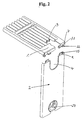
- the panel shown in Figure 1 of a radiator not shown consists of an upper trim part 1 and a side trim part 2, which are rectangular are arranged to each other.
- the with a plurality of passages 3 for heated Air-provided upper trim part 1 covers the top of the radiator, while the the front side with a respective recess 4 and 5 provided lateral trim part 2 for Cover one end of the radiator is used.
- Figure 1 is in Pictured there mounted state of the two trim parts 1 and 2 in the plane of Side panel 2 only to see a rectilinear parting line 6, the limited by 90 ° angled edge strip 7 of the upper trim part 1.
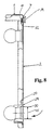
- the lateral covering part 2 at its upper Fairing part 1 facing end face with a 90 ° in the direction of the radiator Angled edge strip 9 is provided, which is on both sides of the recess. 4 extends. In extension of this edge strip 9 are integral with the lateral Cover part 2 connected tabs 10 are formed, the hook-shaped in the direction of the Level of the lateral covering part 2 are bent back.
- the upper trim part 1 is next to the Edge strip 7, which lies in a plane with the lateral covering part 2, still with an adjoining and 90 ° in the direction of the passage openings. 3 provided bent back edge strip 11. With this edge strip 11 are in turn integrally connected four U-shaped bent tabs 12, which extend into areas below the Edge strip 11 extend.
- Figure 5 shows that the trim parts 1 and 2 inclined at an angle ⁇ of 30 ° to each other must be approximated to each other, wherein according to Figure 6, the edge strip. 9 of the side trim part 2 is inserted into the groove formed by the tab 12.
- FIG. 6 shows the lining parts 1 and 2 in a section plane shifted in parallel, in FIG which is an upper flap 12, but no lower flap 10, but only the edge strip. 9 located.
- Figure 7 shows the two trim parts 1 and 2 still in a mutually inclined Arrangement, wherein the tabs 10 of the lateral trim part 2 already the edge strip 11 of the upper trim part 1 have included.
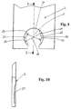
- Figure 9 shows that the lower recess 5 of the side trim part 2 at opposite sides with edge regions 20 and 21 is provided, the edges 22 and 23 lie on a common circle. Between the two edge regions 20 and 21 there is a diameter-extended area 24. In this area 24 is the Diameter 25 slightly larger than the removable from Figure 4 diameter 26 of the usable plastic sleeve 27.
- the plastic sleeve 27 has a longitudinal slot 28 which in its width is adapted to a not shown connecting line, to which the Plastic sleeve 27 must be pushed.
- the plastic sleeve 27 has a front side arranged stop flange 29, to which a recess 30 in the form of a groove followed.
- the outer diameter of the plastic sleeve 27 goes back to a diameter 32, slightly smaller than the diameter 33 of a part-circular and of the Edge strips 20 and 21 limited portion of the recess 5 is. That way initially insert the plastic sleeve 27 without resistance in the recess 5.
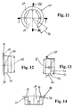
- Figure 15 shows the arrangement of five snap hooks 37, 38 and 39, radially over the inner lateral surface 40 of the plastic sleeve 27 protrude.
- two snap hooks 37 are integral with the inner one Formed surface 40 and extend - adjacent to the longitudinal slot 28 - over an angular range of about 180 ° (see Figure 11).
- These snap hooks 37 have a conical extending surface 41 and an opposite perpendicular to the longitudinal axis L of the Plastic sleeve 27 extending end face 42.
- the conical surface 41 is the Sliding the plastic sleeve 27 via a retaining flange 43 to a pipe socket 44th facilitates, while due to the right angle to the longitudinal axis extending end face 42 a Removal of the sleeve is prevented by the pipe socket 44 (see Figure 3).
- the Outer diameter 43 'of the retaining flange 43 is less than the inner diameter 32' of Plastic sleeve 27 in the area behind the snap hook 37th
- the plastic sleeve 27 has three further snap hooks 38 and 39, the exclusively via a web 45 with the plastic sleeve 27 are in communication.
- the web 45 is located on the side of the snap hooks 38, 39, the front side 46, which is supported on the retaining flange 43 of the pipe socket 44, facing away.
- the Snap hooks 38 and 39 are thus each within a window "in the coat of Plastic sleeve 27 arranged and close with its longitudinal axis L an angle of approximately 20 °.
- Figures 16 to 18 can be seen that the plastic sleeve 27 adjacent to the the pipe socket 44 facing away from end face 47 with three on its inner circumferential surface 40th arranged and radially inwardly projecting engagement cam 48 is provided. Adjacent spacer cams are offset by 90 ° to each other. Between these Attack cam 48 and a key-shaped tool 49, which is shown in Figure 25, can be a positive connection produce the rotation of the plastic sleeve 27 to their Longitudinal axis allowed.
- the tool 49 is offset by two by 180 ° arranged mutually and axially projecting pins 50. To the tool 49 to be able to slide over a connecting pipe to be connected to the pipe socket 44, is this provided on a handle 51 opposite side with a slot 52.
- FIGS. 19 to 24 it is shown how the lateral cladding part 2 Locked plastic sleeve 27 can be removed by twisting again.
- rotational movement engages namely the inclined arranged End segment 36 of the stop flange 29 behind a tapered end face of the edge region 20, so that the groove-shaped recess 30 with this edge portion 20 is disengaged.
- the Positive engagement can be completed by a continued rotation of the plastic sleeve 27 be lifted, so that the side panel 2 of the still with the Holding flange 43 of the pipe socket 44 connected plastic sleeve 27 are deducted can.
- Due to the frontally open recess 5 occurs when swiveling away the side trim part 2 around the hinged connection to the upper trim part 1 to no collision with the connection line.
- the isolated on the pipe socket 44 remaining plastic sleeve 27 can be after removal of the lateral trim part 2 due to their material elastic properties by easily remove expansion from the retaining flange 43.
Landscapes
- Engineering & Computer Science (AREA)
- Physics & Mathematics (AREA)
- Thermal Sciences (AREA)
- Chemical & Material Sciences (AREA)
- Combustion & Propulsion (AREA)
- Mechanical Engineering (AREA)
- General Engineering & Computer Science (AREA)
- Connection Of Plates (AREA)
- Cold Cathode And The Manufacture (AREA)
- Led Device Packages (AREA)
- Cooling, Air Intake And Gas Exhaust, And Fuel Tank Arrangements In Propulsion Units (AREA)
- Domestic Hot-Water Supply Systems And Details Of Heating Systems (AREA)
- Lining Or Joining Of Plastics Or The Like (AREA)
- Finger-Pressure Massage (AREA)
- Cathode-Ray Tubes And Fluorescent Screens For Display (AREA)
- Overhead Projectors And Projection Screens (AREA)
- Resistance Heating (AREA)
- Cookers (AREA)
- Thermotherapy And Cooling Therapy Devices (AREA)
- Housings, Intake/Discharge, And Installation Of Fluid Heaters (AREA)
- Insertion Pins And Rivets (AREA)
Priority Applications (1)
| Application Number | Priority Date | Filing Date | Title |
|---|---|---|---|
| EP03026302A EP1439352A1 (de) | 1998-01-23 | 1999-01-07 | Heizkörperverkleidung |
Applications Claiming Priority (2)
| Application Number | Priority Date | Filing Date | Title |
|---|---|---|---|
| DE29801129U DE29801129U1 (de) | 1998-01-23 | 1998-01-23 | Heizkörperverkleidung |
| DE29801129U | 1998-01-23 |
Related Child Applications (1)
| Application Number | Title | Priority Date | Filing Date |
|---|---|---|---|
| EP03026302A Division EP1439352A1 (de) | 1998-01-23 | 1999-01-07 | Heizkörperverkleidung |
Publications (3)
| Publication Number | Publication Date |
|---|---|
| EP0931987A2 EP0931987A2 (de) | 1999-07-28 |
| EP0931987A3 EP0931987A3 (de) | 2001-11-21 |
| EP0931987B1 true EP0931987B1 (de) | 2005-01-12 |
Family
ID=8051662
Family Applications (2)
| Application Number | Title | Priority Date | Filing Date |
|---|---|---|---|
| EP99100151A Expired - Lifetime EP0931987B1 (de) | 1998-01-23 | 1999-01-07 | Heizkörperverkleidung |
| EP03026302A Withdrawn EP1439352A1 (de) | 1998-01-23 | 1999-01-07 | Heizkörperverkleidung |
Family Applications After (1)
| Application Number | Title | Priority Date | Filing Date |
|---|---|---|---|
| EP03026302A Withdrawn EP1439352A1 (de) | 1998-01-23 | 1999-01-07 | Heizkörperverkleidung |
Country Status (7)
| Country | Link |
|---|---|
| EP (2) | EP0931987B1 (cs) |
| AT (1) | ATE287069T1 (cs) |
| CZ (1) | CZ298344B6 (cs) |
| DE (3) | DE29801129U1 (cs) |
| PL (1) | PL195607B1 (cs) |
| SK (1) | SK286321B6 (cs) |
| TR (1) | TR199802725A2 (cs) |
Families Citing this family (4)
| Publication number | Priority date | Publication date | Assignee | Title |
|---|---|---|---|---|
| DE29817420U1 (de) * | 1998-09-29 | 1999-01-28 | Kermi Gmbh, 94447 Plattling | Befestigungseinrichtung bzw. Anordnung mit dieser |
| ES2231045B1 (es) * | 2004-11-03 | 2007-07-16 | Bsh Ufesa Industrial, S.A. | Estructura de cuerpo calefactor con una cubierta. |
| FR3035955B1 (fr) * | 2015-05-06 | 2019-04-19 | Valeo Systemes Thermiques | Echangeur de chaleur comportant un dispositif de protection |
| CN117823987B (zh) * | 2024-01-02 | 2024-08-27 | 缙云县盛大实业有限公司 | 一种可拆卸钢板散热器结构 |
Family Cites Families (11)
| Publication number | Priority date | Publication date | Assignee | Title |
|---|---|---|---|---|
| DE8902961U1 (de) * | 1989-03-10 | 1989-05-11 | Kermi GmbH, 8350 Plattling | Heizkörperverkleidung |
| DE8904646U1 (de) * | 1989-04-13 | 1989-05-24 | Fa. Kurt Wiemann, 5870 Hemer | Blende zur seitlichen Verkleidung von Flachheizkörpern |
| DE8912436U1 (de) * | 1989-10-20 | 1989-12-07 | Paul Edelhoff KG, 5860 Iserlohn | Verkleidung für einen Plattenheizkörper |
| DE4023548A1 (de) * | 1990-07-25 | 1992-02-06 | Ulamo Beheer Bv | Abdeckplatte fuer die seitenraender von flachheizkoerpern |
| DE9014178U1 (de) * | 1990-10-12 | 1990-12-20 | Fa. Wolfgang Förster, 5870 Hemer | Mehrplattenheizkörper |
| DE29505238U1 (de) * | 1995-03-28 | 1995-06-01 | Paul Edelhoff KG, 58638 Iserlohn | Verkleidung für einen Plattenheizkörper |
| DE29604834U1 (de) * | 1996-03-15 | 1996-05-09 | Ulamo Beheer B.V., Ulft | Randabdeckung für Flachheizkörper |
| DE29607615U1 (de) * | 1996-04-26 | 1996-07-11 | Förster, Wolfgang, 58675 Hemer | Mehrplattenheizkörper |
| DE29707969U1 (de) * | 1997-05-02 | 1997-07-03 | Paul Edelhoff GmbH & Co. KG, 58638 Iserlohn | Verkleidung für einen Flachheizkörper |
| DE29707971U1 (de) * | 1997-05-02 | 1997-06-26 | Paul Edelhoff GmbH & Co. KG, 58638 Iserlohn | Verkleidung für einen Flachheizkörper |
| DE29710290U1 (de) * | 1997-06-12 | 1997-08-07 | Paul Edelhoff GmbH & Co. KG, 58638 Iserlohn | Verkleidung für einen Flachheizkörper |
-
1998
- 1998-01-23 DE DE29801129U patent/DE29801129U1/de not_active Expired - Lifetime
- 1998-05-13 DE DE19821421A patent/DE19821421B4/de not_active Expired - Lifetime
- 1998-12-28 TR TR1998/02725A patent/TR199802725A2/xx unknown
-
1999
- 1999-01-07 AT AT99100151T patent/ATE287069T1/de active
- 1999-01-07 DE DE59911418T patent/DE59911418D1/de not_active Expired - Lifetime
- 1999-01-07 EP EP99100151A patent/EP0931987B1/de not_active Expired - Lifetime
- 1999-01-07 EP EP03026302A patent/EP1439352A1/de not_active Withdrawn
- 1999-01-15 SK SK58-99A patent/SK286321B6/sk not_active IP Right Cessation
- 1999-01-20 CZ CZ0019599A patent/CZ298344B6/cs not_active IP Right Cessation
- 1999-01-20 PL PL330951A patent/PL195607B1/pl unknown
Also Published As
| Publication number | Publication date |
|---|---|
| DE59911418D1 (de) | 2005-02-17 |
| SK5899A3 (en) | 2000-03-13 |
| PL195607B1 (pl) | 2007-10-31 |
| SK286321B6 (en) | 2008-07-07 |
| DE19821421B4 (de) | 2004-04-08 |
| EP0931987A2 (de) | 1999-07-28 |
| EP1439352A1 (de) | 2004-07-21 |
| ATE287069T1 (de) | 2005-01-15 |
| TR199802725A2 (xx) | 1999-08-23 |
| CZ298344B6 (cs) | 2007-09-05 |
| EP0931987A3 (de) | 2001-11-21 |
| DE19821421A1 (de) | 1999-07-29 |
| PL330951A1 (en) | 1999-08-02 |
| CZ19599A3 (cs) | 1999-08-11 |
| DE29801129U1 (de) | 1998-03-26 |
Similar Documents
| Publication | Publication Date | Title |
|---|---|---|
| DE19533727C2 (de) | Spiral-flexibles Halteelement | |
| EP0515657B1 (de) | Zusammengesetztes radial-axial-gleitlager und verfahren zu seiner herstellung | |
| DE19617269C2 (de) | Mehrteilige Fassadenklammer | |
| EP3472904B1 (de) | Scharnieranordnung für einen schaltschrank | |
| DE2501611C3 (de) | Flanschverbindung für rechteckige Klimatisierungskanäle | |
| DE102012009173A1 (de) | Toleranzausgleichseinrichtung | |
| EP1573144A1 (de) | Flächiges metallelement und profilelement | |
| DE3323498C2 (cs) | ||
| EP0931987B1 (de) | Heizkörperverkleidung | |
| EP2754805A2 (de) | Riegelstange für einen Riegelstangenbeschlag | |
| DE19707564A1 (de) | Montagesystem zur Halterung von Verkleidungselementen an Bauwerken | |
| EP1837479A2 (de) | Verbindungsanordnung für einen Lamellen aufweisenden Raffstore oder dergleichen | |
| EP2759666B1 (de) | Beschlaganordnung mit einem Profilelement | |
| EP0386496B1 (de) | Heizkörperverkleidung | |
| AT500181B1 (de) | Tür- oder fensterbeschlag | |
| DE19514963B4 (de) | Kraftfahrzeugtür | |
| EP1997770B2 (de) | Aufzugstürblatt | |
| EP1646756B1 (de) | Verbindungssystem für profilschienen | |
| DE102013100308A1 (de) | Riegelstangenbeschlag für ein Fenster oder eine Tür | |
| EP3029244B1 (de) | Blendenanordnung für einen beschlag | |
| DE102004050074B4 (de) | Fahrzeugtür | |
| EP1869278B1 (de) | Verbundprofil und verfahren zur herstellung eines verbundprofils für rahmen von wandelementen, türen oder fenstern | |
| EP2689078B1 (de) | Profilelement und verfahren zum herstellen eines profilelements | |
| DE19734647B4 (de) | Beschlagteil an einem Flügel oder einem festen Rahmen eines Fensters, einer Tür od. dgl. | |
| DE102024109048B3 (de) | Teilesatz für eine Bodendichtung eines Türflügels, insbesondere einer Rauchschutztür, mit Adapter |
Legal Events
| Date | Code | Title | Description |
|---|---|---|---|
| PUAI | Public reference made under article 153(3) epc to a published international application that has entered the european phase |
Free format text: ORIGINAL CODE: 0009012 |
|
| AK | Designated contracting states |
Kind code of ref document: A2 Designated state(s): AT BE CH CY DE DK ES FI FR GB GR IE IT LI LU MC NL PT SE Kind code of ref document: A2 Designated state(s): AT BE CH DE ES FI FR GB IT LI NL SE |
|
| AX | Request for extension of the european patent |
Free format text: AL;LT;LV;MK;RO;SI |
|
| RAP1 | Party data changed (applicant data changed or rights of an application transferred) |
Owner name: BLACK KNIGHT BV |
|
| 111Z | Information provided on other rights and legal means of execution |
Free format text: 20010124 AT BE CH CY DE DK ES FI FR GB GR IE IT LI LU MC NL PT SE |
|
| RAP1 | Party data changed (applicant data changed or rights of an application transferred) |
Owner name: CARADON HEATING EUROPE B.V. |
|
| PUAL | Search report despatched |
Free format text: ORIGINAL CODE: 0009013 |
|
| AK | Designated contracting states |
Kind code of ref document: A3 Designated state(s): AT BE CH CY DE DK ES FI FR GB GR IE IT LI LU MC NL PT SE |
|
| AX | Request for extension of the european patent |
Free format text: AL;LT;LV;MK;RO;SI |
|
| 111Z | Information provided on other rights and legal means of execution |
Free format text: 20011217 NL |
|
| 17P | Request for examination filed |
Effective date: 20020211 |
|
| AKX | Designation fees paid |
Free format text: AT BE CH DE ES FI FR GB IT LI NL SE |
|
| 17Q | First examination report despatched |
Effective date: 20030702 |
|
| GRAP | Despatch of communication of intention to grant a patent |
Free format text: ORIGINAL CODE: EPIDOSNIGR1 |
|
| GRAS | Grant fee paid |
Free format text: ORIGINAL CODE: EPIDOSNIGR3 |
|
| GRAA | (expected) grant |
Free format text: ORIGINAL CODE: 0009210 |
|
| AK | Designated contracting states |
Kind code of ref document: B1 Designated state(s): AT BE CH DE ES FI FR GB IT LI NL SE |
|
| PG25 | Lapsed in a contracting state [announced via postgrant information from national office to epo] |
Ref country code: IT Free format text: LAPSE BECAUSE OF NON-PAYMENT OF DUE FEES;WARNING: LAPSES OF ITALIAN PATENTS WITH EFFECTIVE DATE BEFORE 2007 MAY HAVE OCCURRED AT ANY TIME BEFORE 2007. THE CORRECT EFFECTIVE DATE MAY BE DIFFERENT FROM THE ONE RECORDED. Effective date: 20050112 |
|
| REG | Reference to a national code |
Ref country code: GB Ref legal event code: FG4D Free format text: NOT ENGLISH |
|
| REG | Reference to a national code |
Ref country code: CH Ref legal event code: EP |
|
| REF | Corresponds to: |
Ref document number: 59911418 Country of ref document: DE Date of ref document: 20050217 Kind code of ref document: P |
|
| PG25 | Lapsed in a contracting state [announced via postgrant information from national office to epo] |
Ref country code: ES Free format text: LAPSE BECAUSE OF FAILURE TO SUBMIT A TRANSLATION OF THE DESCRIPTION OR TO PAY THE FEE WITHIN THE PRESCRIBED TIME-LIMIT Effective date: 20050423 |
|
| REG | Reference to a national code |
Ref country code: SE Ref legal event code: TRGR |
|
| REG | Reference to a national code |
Ref country code: CH Ref legal event code: NV Representative=s name: LUCHS & PARTNER PATENTANWAELTE |
|
| REG | Reference to a national code |
Ref country code: GB Ref legal event code: 710B Free format text: EXTENSION APPLICATION: APPLICATION FOR EXTENSION OF THE PERIOD(S) PRESCRIBED BY RULE(S) SCHEDULE 4 PARA 2 FILED ON 20050712. |
|
| PLBE | No opposition filed within time limit |
Free format text: ORIGINAL CODE: 0009261 |
|
| STAA | Information on the status of an ep patent application or granted ep patent |
Free format text: STATUS: NO OPPOSITION FILED WITHIN TIME LIMIT |
|
| GBT | Gb: translation of ep patent filed (gb section 77(6)(a)/1977) |
Effective date: 20051206 |
|
| ET | Fr: translation filed | ||
| 26N | No opposition filed |
Effective date: 20051013 |
|
| PGFP | Annual fee paid to national office [announced via postgrant information from national office to epo] |
Ref country code: CH Payment date: 20080228 Year of fee payment: 10 |
|
| PGFP | Annual fee paid to national office [announced via postgrant information from national office to epo] |
Ref country code: FI Payment date: 20080103 Year of fee payment: 10 |
|
| REG | Reference to a national code |
Ref country code: CH Ref legal event code: PL |
|
| PG25 | Lapsed in a contracting state [announced via postgrant information from national office to epo] |
Ref country code: LI Free format text: LAPSE BECAUSE OF NON-PAYMENT OF DUE FEES Effective date: 20090131 Ref country code: FI Free format text: LAPSE BECAUSE OF NON-PAYMENT OF DUE FEES Effective date: 20090107 Ref country code: CH Free format text: LAPSE BECAUSE OF NON-PAYMENT OF DUE FEES Effective date: 20090131 |
|
| PGFP | Annual fee paid to national office [announced via postgrant information from national office to epo] |
Ref country code: IT Payment date: 20080108 Year of fee payment: 10 |
|
| PGRI | Patent reinstated in contracting state [announced from national office to epo] |
Ref country code: IT Effective date: 20091201 |
|
| PGRI | Patent reinstated in contracting state [announced from national office to epo] |
Ref country code: IT Effective date: 20091201 |
|
| REG | Reference to a national code |
Ref country code: DE Ref legal event code: R081 Ref document number: 59911418 Country of ref document: DE Owner name: CARADON STELRAD B.V., BE Free format text: FORMER OWNER: CARADON HEATING EUROPE B.V., AMSTERDAM, NL Effective date: 20110329 |
|
| REG | Reference to a national code |
Ref country code: NL Ref legal event code: SD Effective date: 20140109 |
|
| REG | Reference to a national code |
Ref country code: FR Ref legal event code: CD Owner name: CARADON STELRAD B.V., NL Effective date: 20140108 Ref country code: FR Ref legal event code: CA Effective date: 20140108 |
|
| REG | Reference to a national code |
Ref country code: FR Ref legal event code: PLFP Year of fee payment: 18 |
|
| REG | Reference to a national code |
Ref country code: FR Ref legal event code: PLFP Year of fee payment: 19 |
|
| REG | Reference to a national code |
Ref country code: FR Ref legal event code: PLFP Year of fee payment: 20 |
|
| PGFP | Annual fee paid to national office [announced via postgrant information from national office to epo] |
Ref country code: FR Payment date: 20171211 Year of fee payment: 20 |
|
| PGFP | Annual fee paid to national office [announced via postgrant information from national office to epo] |
Ref country code: GB Payment date: 20171211 Year of fee payment: 20 |
|
| PGFP | Annual fee paid to national office [announced via postgrant information from national office to epo] |
Ref country code: NL Payment date: 20180104 Year of fee payment: 20 |
|
| PGFP | Annual fee paid to national office [announced via postgrant information from national office to epo] |
Ref country code: DE Payment date: 20180131 Year of fee payment: 20 |
|
| PGFP | Annual fee paid to national office [announced via postgrant information from national office to epo] |
Ref country code: AT Payment date: 20180109 Year of fee payment: 20 Ref country code: SE Payment date: 20180115 Year of fee payment: 20 Ref country code: BE Payment date: 20171222 Year of fee payment: 20 |
|
| REG | Reference to a national code |
Ref country code: DE Ref legal event code: R071 Ref document number: 59911418 Country of ref document: DE |
|
| REG | Reference to a national code |
Ref country code: NL Ref legal event code: MK Effective date: 20190106 |
|
| REG | Reference to a national code |
Ref country code: GB Ref legal event code: PE20 Expiry date: 20190106 |
|
| REG | Reference to a national code |
Ref country code: BE Ref legal event code: MK Effective date: 20190107 Ref country code: BE Ref legal event code: HC Owner name: CARADON STELRAD B.V.; NL Free format text: DETAILS ASSIGNMENT: CHANGE OF OWNER(S), CHANGEMENT NOM PROPRIETAIRE; FORMER OWNER NAME: CARADON HEATING EUROPE B.V. Effective date: 20140526 |
|
| REG | Reference to a national code |
Ref country code: AT Ref legal event code: MK07 Ref document number: 287069 Country of ref document: AT Kind code of ref document: T Effective date: 20190107 |
|
| PG25 | Lapsed in a contracting state [announced via postgrant information from national office to epo] |
Ref country code: GB Free format text: LAPSE BECAUSE OF EXPIRATION OF PROTECTION Effective date: 20190106 |