EP0933106A2 - Fahrspielzeug mit Reibradantrieb - Google Patents
Fahrspielzeug mit Reibradantrieb Download PDFInfo
- Publication number
- EP0933106A2 EP0933106A2 EP99102112A EP99102112A EP0933106A2 EP 0933106 A2 EP0933106 A2 EP 0933106A2 EP 99102112 A EP99102112 A EP 99102112A EP 99102112 A EP99102112 A EP 99102112A EP 0933106 A2 EP0933106 A2 EP 0933106A2
- Authority
- EP
- European Patent Office
- Prior art keywords
- driving
- drive
- wheel
- motor
- driving toy
- Prior art date
- Legal status (The legal status is an assumption and is not a legal conclusion. Google has not performed a legal analysis and makes no representation as to the accuracy of the status listed.)
- Granted
Links
- 239000000725 suspension Substances 0.000 claims description 5
- 238000006073 displacement reaction Methods 0.000 claims description 2
- 230000002787 reinforcement Effects 0.000 claims 1
- 230000005611 electricity Effects 0.000 abstract 1
- 210000003746 feather Anatomy 0.000 description 3
- 230000005540 biological transmission Effects 0.000 description 2
- 230000002349 favourable effect Effects 0.000 description 2
- 230000036316 preload Effects 0.000 description 2
- 230000001133 acceleration Effects 0.000 description 1
- 238000011109 contamination Methods 0.000 description 1
- 230000001419 dependent effect Effects 0.000 description 1
- 238000011161 development Methods 0.000 description 1
- 230000018109 developmental process Effects 0.000 description 1
- 239000004033 plastic Substances 0.000 description 1
- 230000002028 premature Effects 0.000 description 1
Images


Classifications
-
- A—HUMAN NECESSITIES
- A63—SPORTS; GAMES; AMUSEMENTS
- A63H—TOYS, e.g. TOPS, DOLLS, HOOPS OR BUILDING BLOCKS
- A63H31/00—Gearing for toys
- A63H31/04—Friction mechanisms
-
- A—HUMAN NECESSITIES
- A63—SPORTS; GAMES; AMUSEMENTS
- A63H—TOYS, e.g. TOPS, DOLLS, HOOPS OR BUILDING BLOCKS
- A63H18/00—Highways or trackways for toys; Propulsion by special interaction between vehicle and track
- A63H18/16—Control of vehicle drives by interaction between vehicle and track; Control of track elements by vehicles
- A63H2018/165—Means to improve adhesion of the vehicles on the track, e.g. using magnetic forces
Definitions
- the invention relates to a driving toy, especially for track-guided Car racing tracks, according to the preamble of claim 1.
- Driving toys for car racing tracks generally have two axes, one of which is driven by an electric motor.
- the engine sits there seen in the direction of travel, preferably in front of the rear axle and drives it over a pinion.
- the motor axis runs parallel to Drive thing, with a translation between the motor axis and drive axis is made by means of two gears.
- the Motor axis at right angles to the drive axis, and the power transmission takes place via a gear angular gear, which in further training can also have an idle wheel, with the help of which Control functions are performed.
- the invention is therefore based on the object of having a driving toy motor drive to indicate the susceptibility to wear of the drive is reduced by simple measures.
- a driving toy especially for track-guided car racing tracks, with a drive motor, which is provided with an end drive wheel and with at least one drive wheel of the vehicle is in drive connection
- a drive motor which is provided with an end drive wheel and with at least one drive wheel of the vehicle is in drive connection
- the driving wheel in immediate there is a frictional connection with one of the drive wheels of the toy vehicle.
- a gear transmission is completely dispensed with, so that a corresponding wear of gears is excluded.
- the driving wheel attached to the motor axis acts directly on a driving wheel a, wherein the drive wheel is preferably made of rubber or at least one has a rubber-like surface. Since the drive wheels are also made of rubber exist or have a rubber-like surface, results from the direct contact of the drive wheel with a drive wheel a strong one frictional connection that is quiet, has little slip and one has a long service life.
- the axis of the drive motor is preferably parallel to the drive axis of the vehicle. This means that there are no angular gears, Bevel gear or similar angular connections required. With the help of Invention, it is also easily possible that the drive motor on both End faces are each provided with a drive wheel, the drive wheels each on Act the drive wheel of the vehicle. This can drive power be made more balanced. In a further embodiment of the invention also be provided, both the rear axle of the toy and the The front axle of the toy vehicle each has a drive motor with one or two Assign driving wheels. This allows an all-wheel drive to be realized, the high Offers acceleration options, and especially not track-bound vehicles, for example for remote-controlled off-road vehicles, can be used so that large with such a vehicle Terrain slopes can be overcome.
- the drive axle or the drive axles of the toy vehicle can be undivided or divided into two.
- the two-part design has in particular Advantages when driving wheels are used in pairs. If at one divided drive axle each part of the drive axle has its own motor is assigned, it is possible through targeted control of the energy supply of the individual motors on the respective drive axles different Achieve torques, thereby controlled cornering or changing lanes become possible.
- Driving wheels interchangeable to wear them either against one replace a new driving wheel or to replace a driving wheel with another driving wheel with a changed diameter, so that drive torque and Driving speeds can be changed.
- the drive motor in question is preferably articulated stored in order to change the center distance of the motor to the drive wheel can.
- the articulated mounting of the drive motor is in another Embodiment of the invention preferably chosen so that the drive the motor generates a force component on the drive wheel when loaded, which acts against the drive wheel, so while driving the toy vehicle to increase the frictional force between the driving wheel and the driving wheel.
- the suspension of the drive motor can be designed to be resilient To be able to press the driving wheel against the driving wheel with a resilient preload.
- a rotation of the motor suspension via a swivel joint parallel to Drive axis may be provided. It is also possible to put the engine on one resilient bias to slide slidable to arrange so that the spring force presses the friction wheel of the motor radially against the drive wheel.
- the invention is particularly applicable to track-bound vehicles on a racetrack, but it can also be easily track-bound vehicles can be used.
- Replacement of the drive wheels can be carried out by z.
- B. a tire change is carried out from a rear to a front rim.
- drive wheel is not based on the real thing limited to the ground running wheel, but also includes a gradation of the Drive wheel with a smaller diameter, on which the drive wheel acts or on wheel parallel to the wheel not running on the ground, whereby contamination of the drive wheel and drive wheel surfaces is prevented can be.
- the driving toy shown in FIG. 1 has a base plate 1 on which a chassis upper part, not shown, can be fitted. Located in the rear area there are two drive wheels 2, 3 which are rigid with one another via a drive axle 13 are connected.
- the drive axle can also be formed in two parts, wherein they are available in the holding blocks in both the one and two-part versions 11, 12 is mounted.
- the holding blocks 11, 12 are preferably made of plastic. However, in an improved quality they can also be used as ball bearings be trained.
- a hinge axis 14 is arranged parallel to the drive axis 13, the two engine mounts 9, 10 connected to the bottom plate carries to the engine 6 articulated.
- the motor has a continuous motor axis 16 the ends of which are each drive wheels 7 and 8 respectively.
- the position of the motor with respect to the Joint axis 14 and the drive axis 13 can be adjusted so that the Driving wheels 7, 8 with sufficient pressure against the driving wheels 2, 3 press on.
- FIG. 1 shows a motor 6 with two drive wheels 7, 8 the invention nevertheless in a simple embodiment with only one driving wheel usable.
- the drive wheels 7 and 8 arranged at the end of the motor axis 16 exist made of rubber or at least have a rubber-like surface to a to achieve strong frictional engagement with the drive wheels 2 and 3.
- the drive wheels 7 and 8 are designed interchangeably, so that they Wear can be changed or with another driving wheel larger or smaller diameter can be exchanged.
- the articulated suspension of the motor allows the radius changes of the Driving wheels can be compensated for, as in further detail with reference to FIG. 4 is explained.
- the front wheels 4, 5 are fastened on a front axle 21.
- the axis 21 can also be formed in one or two parts.
- driving toy can a corresponding one on the front axle 21 and the front wheels 4, 5 Drive arrangement, as it is assigned to the rear axle, are used.
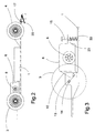
- FIG. 2 shows a driving toy according to FIG. 1 in a side view. It is clear shown that the drive wheel 8 in direct contact with the drive wheel 3rd stands. Since the engine efficiency is particularly favorable at high engine speeds Motor, the diameter of the driving wheel is relatively small compared to that Diameter of the drive wheel 3 selected.
- FIG. 3 shows a detailed view of the drive area of the toy vehicle. It is shown here in particular that the motor 6 on an articulated axis 14 is mounted so that it can perform a pivoting movement.
- the motor 6 is raised, so that its drive wheel 8 against the surface of the drive wheel 3 with a certain preload.
- the clamping screw 15 can Swivel range of the motor 6 can be limited.
- the holder 23 therefore abuts the head of the clamping screw 15, this means that the wear of the drive wheel 8 has become so great that a Exchange is required. This is shown by the increased slip between Driving wheel 8 and driving wheel 3.
- Fig. 4 shows a symbolic representation of the drive connection between Driving wheel 8 and driving wheel 3.
- the hinge axis 14 is here below the horizontal 24 between drive axle 13 and motor axle 16.
- the contact point of drive wheel 8 and drive wheel 3 lies in the line of intersection between the horizontal 24 and one Vertical. If the drive from the drive wheel 8 and drive wheel 3 in the direction of arrow shown is carried out, the drive torque of Driving wheel 8 that the connecting axis 28 between the hinge axis 14 and Motor axis 16 is raised upwards so that the contact point 30th between drive wheel 3 and drive wheel 8 has a tendency towards the arc 29 emigrate. As can be clearly seen, this leads to an increase in Pressing force of the drive wheel 8 against the drive wheel 3 practical operation achieves an increase in driving force at the same time an increase in the contact pressure of the drive wheel 8 on the drive wheel 3.
- the motor 6 is on one on the base plate guided in the longitudinal direction of the vehicle arranged carriage 31 attached.
- the carriage 31 is spring-loaded between slide 31 and base plate 1 of the springs 32, 33 in the direction of the Drive wheel 3 pressed.
- the Reibard 8 acts radially in the direction of the Drive axis 13 and there is a relatively large displacement that can be achieved It is advantageous if a change in diameter of the friction wheel 8 or Drive wheel 3 is desired.
- the sled is set on the base plate via two with play Screws 35, 36 are held, which are arranged in guides of the carriage and in which the springs 32, 33 are also mounted.
Landscapes
- Toys (AREA)
Abstract
Description
- Fig. 1
- eine Aufsicht auf ein Fahrspielzeug nach der Erfindung bei entferntem Chassisaufbau,
- Fig. 2
- eine Seitenansicht eines Fahrspielzeuges nach Fig. 1,
- Fig. 3
- eine Detailansicht zur Darstellung einer Ausführungsform einer Motorbefestigung,
- Fig. 4
- eine graphische Darstellung zur Erläuterung der Andruckkräfte beim Betrieb eines derartigen Fahrspielzeuges, und
- Fig. 5
- eine alternative Ausführungsform zur Motorbefestigung.
- 1
- Bodenplatte
- 2
- Antriebsrad
- 3
- Antriebsrad
- 4
- Vorderrad
- 5
- Vorderrad
- 6
- Motor
- 7
- Treibrad
- 8
- Treibrad
- 9
- Motoraufhängung
- 10
- Motoraufhänung
- 11
- Halteblock
- 12
- Halteblock
- 13
- Antriebsachse
- 14
- Gelenkachse
- 15
- Spannschraube
- 16
- Motorachse
- 17
- Gelenk
- 18
- Platte
- 19
- Kontaktbürste
- 20
- Kontaktbürste
- 21
- Vorderachse
- 22
- Feder
- 23
- Halter
- 24
- Horizontale
- 25
- Bogen
- 26
- Vertikale
- 27
- Bogen
- 28
- Verbindungsachse
- 29
- Bogen
- 30
- Kontaktpunkt
- 31
- Schlitten
- 32
- Feder
- 33
- Feder
- 34
- Magnet
- 35
- Schraube
- 36
- Schraube
Claims (12)
- Fahrspielzeug, insbesondere für spurgeführte Autorennbahnen, mit einem Antriebsmotor (6), der mit einem stirnseitigen Treibrad (7, 8) versehen ist und mit wenigstens einem Antriebsrad (2, 3) des Fahrspielzeuges in Antriebsverbindung steht, dadurch gekennzeichnet, daß das Treibrad (7,8) in unmittelbarer reibschlüssiger Verbindung mit dem Antriebsrad (2, 3) steht.
- Fahrspielzeug nach Anspruch 1, dadurch gekennzeichnet, daß das Treibrad eine aus Gummi bestehende oder gummiartige Oberfläche aufweist.
- Fahrspielzeug nach Anspruch 1, dadurch gekennzeichnet, daß die Motorachse (16) achsparallel zur Antriebsachse (13) des Fahrspielzeuges ausgerichtet ist.
- Fahrspielzeug nach Anspruch 3, dadurch gekennzeichnet, daß der Antriebsmotor (6) an beiden Stirnseiten mit je einem Treibrad (7, 8) versehen ist, und daß die Treibräder (7,8) jeweils auf ein Antriebsrad (2,3) des Fahrspielzeuges einwirken.
- Fahrspielzeug nach Anspruch 1 oder 3, dadurch gekennzeichnet, daß sowohl der Hinterachse (13) als auch der Vorderachse (21) des Fahrspielzeuges je ein Antriebsmotor zugeordnet ist.
- Fahrspielzeug nach Anspruch 4 oder 5, dadurch gekennzeichnet, daß die Antriebsachse (13, 21) zweigeteilt ausgebildet ist.
- Fahrspielzeug nach einem oder mehreren der vorhergehenden Ansprüche, dadurch gekennzeichnet, daß das Treibrad (7, 8) gegen ein Treibrad mit verändertem Durchmesser austauschbar ist.
- Fahrspielzeug nach einem oder mehreren der vorhergehenden Ansprüche, dadurch gekennzeichnet, daß das Treibrad (7, 8) des Antriebsmotors (6) durch federnd befestigte Aufhängung des Antriebmotors unter Vorspannung gegen das Antriebsrad gedrückt wird.
- Fahrspielzeug nach einem oder mehreren der vorhergehenden Ansprüche, dadurch gekennzeichnet, daß der Antriebsmotor (6) einseitig gelenkig am Chassis (1) des Fahrspielzeuges gelagert ist, wobei der Lagerungsort derartig gewählt ist, daß beim Antrieb des Fahrspielzeuges in Vorwärtsrichtung und Erhöhung der Antriebslast eine Verstärkung des Anpreßdrucks des Treibrades (7, 8) gegen das Antriebsrad (2, 3) eintritt.
- Fahrspielzeug nach Anspruch 8, dadurch gekennzeichnet, daß der Antriebsmotor auf einem gegenüber der Bodenplatte verschieblich geführten Schlitten (31) angeordnet ist.
- Fahrspielzeug nach Anspruch 10, dadurch gekennzeichnet, daß die Verschieberichtung des Schlittens (31) radial zur Antriebsachse verläuft.
- Fahrspielzeug nach Anspruch 10, dadurch gekennzeichnet, daß der Schlitten (31) einen Haltemagneten (34) zum Andrücken des Fahrspielzeugs an die Fahrbahn aufweist.
Applications Claiming Priority (2)
| Application Number | Priority Date | Filing Date | Title |
|---|---|---|---|
| DE19804292 | 1998-02-04 | ||
| DE19804292A DE19804292A1 (de) | 1998-02-04 | 1998-02-04 | Fahrspielzeug mit Reibradantrieb |
Publications (3)
| Publication Number | Publication Date |
|---|---|
| EP0933106A2 true EP0933106A2 (de) | 1999-08-04 |
| EP0933106A3 EP0933106A3 (de) | 2001-01-03 |
| EP0933106B1 EP0933106B1 (de) | 2003-08-13 |
Family
ID=7856573
Family Applications (1)
| Application Number | Title | Priority Date | Filing Date |
|---|---|---|---|
| EP99102112A Expired - Lifetime EP0933106B1 (de) | 1998-02-04 | 1999-02-03 | Fahrspielzeug mit Reibradantrieb |
Country Status (5)
| Country | Link |
|---|---|
| US (1) | US6062943A (de) |
| EP (1) | EP0933106B1 (de) |
| AT (1) | ATE246947T1 (de) |
| DE (2) | DE19804292A1 (de) |
| ES (1) | ES2202938T3 (de) |
Families Citing this family (8)
| Publication number | Priority date | Publication date | Assignee | Title |
|---|---|---|---|---|
| US6231422B1 (en) * | 1999-05-21 | 2001-05-15 | Bong Kyu Choi | Toy automobile |
| FR2840541B1 (fr) * | 2002-06-11 | 2005-02-25 | Janick Simeray | Jouet mobile motorise a telecommande |
| DE102004011936B3 (de) * | 2004-03-11 | 2005-08-25 | Dr.Ing.H.C. F. Porsche Ag | Spielfahrzeug, insbesondere für spurgeführte Rennbahnen |
| DE102004011933B4 (de) * | 2004-03-11 | 2008-04-10 | Dr.Ing.H.C. F. Porsche Ag | Stromabnahmeeinrichtung für ein spurgeführtes Spielfahrzeug |
| DE102004011937A1 (de) | 2004-03-11 | 2005-10-06 | Dr.Ing.H.C. F. Porsche Ag | Führungseinrichtung für ein spurgeführtes Spielfahrzeug |
| DE102005002883B4 (de) * | 2005-01-21 | 2013-10-10 | Dr. Ing. H.C. F. Porsche Aktiengesellschaft | Hinterachse eines Fahrgestells für ein Spielfahrzeug |
| US9440159B1 (en) * | 2012-12-21 | 2016-09-13 | Shoot The Moon Products Ii, Llc | Rechargeable toy vehicles |
| ES1300656Y (es) * | 2023-03-10 | 2023-09-06 | Quis Informatica Y Comunicacion Sl | Soporte de motor para coches de slot |
Family Cites Families (5)
| Publication number | Priority date | Publication date | Assignee | Title |
|---|---|---|---|---|
| US3553886A (en) * | 1968-04-03 | 1971-01-12 | Harry M Hamilton | Clutch and drive assembly for model vehicles |
| US4045908A (en) * | 1974-08-05 | 1977-09-06 | Ideal Toy Corporation | Powered vehicle transport vehicle and track having a well therein |
| DE3047070A1 (de) * | 1980-12-13 | 1982-07-15 | Willy Dipl.-Ing. 4053 Jüchen Bartels | Schlupfregelvorrichtung fuer motorgetriebene fahrzeuge |
| JPS5914696U (ja) * | 1982-07-21 | 1984-01-28 | 株式会社トミー | 玩具用発車装置 |
| JPH0396899U (de) * | 1990-01-23 | 1991-10-03 |
-
1998
- 1998-02-04 DE DE19804292A patent/DE19804292A1/de not_active Withdrawn
-
1999
- 1999-02-03 DE DE59906548T patent/DE59906548D1/de not_active Expired - Lifetime
- 1999-02-03 EP EP99102112A patent/EP0933106B1/de not_active Expired - Lifetime
- 1999-02-03 AT AT99102112T patent/ATE246947T1/de active
- 1999-02-03 ES ES99102112T patent/ES2202938T3/es not_active Expired - Lifetime
- 1999-02-04 US US09/244,157 patent/US6062943A/en not_active Expired - Lifetime
Also Published As
| Publication number | Publication date |
|---|---|
| DE19804292A1 (de) | 1999-08-05 |
| US6062943A (en) | 2000-05-16 |
| DE59906548D1 (de) | 2003-09-18 |
| EP0933106A3 (de) | 2001-01-03 |
| ES2202938T3 (es) | 2004-04-01 |
| EP0933106B1 (de) | 2003-08-13 |
| ATE246947T1 (de) | 2003-08-15 |
Similar Documents
| Publication | Publication Date | Title |
|---|---|---|
| DE69707023T2 (de) | Fahrspielzeug mit veränderlich positionierbaren Rädern | |
| EP0770013B1 (de) | Angetriebenes laufwerk für schienenfahrzeuge mit spurwechseleinrichtung | |
| EP0589864B1 (de) | Triebfahrzeug, insbesondere Eisenbahn-Triebfahrzeug | |
| EP0507137B1 (de) | Lenkbarer Radantrieb | |
| DE3135490A1 (de) | Batteriegetriebenes elektrofahrzeug | |
| EP0933106B1 (de) | Fahrspielzeug mit Reibradantrieb | |
| WO2011113456A1 (de) | Kraftwagen | |
| DE102017003528B4 (de) | Fahrzeug mit hoher Manövrierbarkeit und vier unabhängig voneinander antreibbaren Antriebsrädern | |
| DE19810480B4 (de) | Fahrzeugscheinwerfer mit einem verstellbaren Reflektor | |
| EP0567445B1 (de) | Fahrwerk für Schienenfahrzeuge, insbesondere Niederflurwagen | |
| DE3618308A1 (de) | Radfuehrungsschwinge fuer horizontal schwenkbare schienenraeder | |
| DE1530023B2 (de) | Fahrgestell für ein mehrspuriges spurgebundenes Triebfahrzeug | |
| DE4126311A1 (de) | Elektrokraftwagen mit einer kompakt-antriebseinheit | |
| EP0444016A2 (de) | Triebdrehgestell für elektrische Lokomotiven | |
| DE68901847T2 (de) | Motordrehgestell fuer schienenfahrzeug mit ueber seine ganze laenge durchgehend niedrigem boden. | |
| DE4418480A1 (de) | Vertikalaufzug | |
| DE102008040505A1 (de) | Eigenlenkende Radaufhängung mit Geradführung | |
| DE4443943A1 (de) | Straßenfahrzeug für das Befahren von Straßen- und Schienenwegen | |
| DE3131433C2 (de) | ||
| WO1999046155A1 (de) | Vorrichtung zur übertragung der längskräfte eines drehgestelles auf den wagenkasten eines schienenfahrzeuges, insbesondere eines triebfahrzeuges mit hoher zugkraft | |
| EP1110819B1 (de) | Elektrisch verstellbarer Aussenrückspiegel | |
| DE3714686C1 (en) | Wheel suspension for motor vehicles | |
| DE203895C (de) | ||
| DE3924219C2 (de) | Kupplungsvorrichtung für ein Modellbahn-Gelenkfahrzeug | |
| AT395540B (de) | Modellbahn-gelenkfahrzeug |
Legal Events
| Date | Code | Title | Description |
|---|---|---|---|
| PUAI | Public reference made under article 153(3) epc to a published international application that has entered the european phase |
Free format text: ORIGINAL CODE: 0009012 |
|
| AK | Designated contracting states |
Kind code of ref document: A2 Designated state(s): AT BE CH DE DK ES FI FR GB GR IT LI NL PT SE |
|
| AX | Request for extension of the european patent |
Free format text: AL;LT;LV;MK;RO;SI |
|
| PUAL | Search report despatched |
Free format text: ORIGINAL CODE: 0009013 |
|
| AK | Designated contracting states |
Kind code of ref document: A3 Designated state(s): AT BE CH CY DE DK ES FI FR GB GR IE IT LI LU MC NL PT SE |
|
| AX | Request for extension of the european patent |
Free format text: AL;LT;LV;MK;RO;SI |
|
| RIC1 | Information provided on ipc code assigned before grant |
Free format text: 7A 63H 31/04 A, 7A 63H 17/26 B |
|
| 17P | Request for examination filed |
Effective date: 20010117 |
|
| RAP1 | Party data changed (applicant data changed or rights of an application transferred) |
Owner name: STS RACING GMBH |
|
| AKX | Designation fees paid |
Free format text: AT BE CH DE DK ES FI FR GB GR IT LI NL PT SE |
|
| GRAH | Despatch of communication of intention to grant a patent |
Free format text: ORIGINAL CODE: EPIDOS IGRA |
|
| GRAH | Despatch of communication of intention to grant a patent |
Free format text: ORIGINAL CODE: EPIDOS IGRA |
|
| GRAA | (expected) grant |
Free format text: ORIGINAL CODE: 0009210 |
|
| AK | Designated contracting states |
Designated state(s): AT BE CH DE DK ES FI FR GB GR IT LI NL PT SE |
|
| PG25 | Lapsed in a contracting state [announced via postgrant information from national office to epo] |
Ref country code: NL Free format text: LAPSE BECAUSE OF FAILURE TO SUBMIT A TRANSLATION OF THE DESCRIPTION OR TO PAY THE FEE WITHIN THE PRESCRIBED TIME-LIMIT Effective date: 20030813 Ref country code: FR Free format text: LAPSE BECAUSE OF NON-PAYMENT OF DUE FEES Effective date: 20030813 Ref country code: FI Free format text: LAPSE BECAUSE OF FAILURE TO SUBMIT A TRANSLATION OF THE DESCRIPTION OR TO PAY THE FEE WITHIN THE PRESCRIBED TIME-LIMIT Effective date: 20030813 |
|
| REG | Reference to a national code |
Ref country code: GB Ref legal event code: FG4D Free format text: NOT ENGLISH |
|
| REG | Reference to a national code |
Ref country code: CH Ref legal event code: EP |
|
| GBT | Gb: translation of ep patent filed (gb section 77(6)(a)/1977) | ||
| RAP2 | Party data changed (patent owner data changed or rights of a patent transferred) |
Owner name: STADLBAUER SPIEL- UND FREIZEITARTIKEL GMBH |
|
| REF | Corresponds to: |
Ref document number: 59906548 Country of ref document: DE Date of ref document: 20030918 Kind code of ref document: P |
|
| NLT2 | Nl: modifications (of names), taken from the european patent patent bulletin |
Owner name: STADLBAUER SPIEL- UND FREIZEITARTIKEL GMBH |
|
| PG25 | Lapsed in a contracting state [announced via postgrant information from national office to epo] |
Ref country code: SE Free format text: LAPSE BECAUSE OF FAILURE TO SUBMIT A TRANSLATION OF THE DESCRIPTION OR TO PAY THE FEE WITHIN THE PRESCRIBED TIME-LIMIT Effective date: 20031113 Ref country code: GR Free format text: LAPSE BECAUSE OF FAILURE TO SUBMIT A TRANSLATION OF THE DESCRIPTION OR TO PAY THE FEE WITHIN THE PRESCRIBED TIME-LIMIT Effective date: 20031113 Ref country code: DK Free format text: LAPSE BECAUSE OF FAILURE TO SUBMIT A TRANSLATION OF THE DESCRIPTION OR TO PAY THE FEE WITHIN THE PRESCRIBED TIME-LIMIT Effective date: 20031113 |
|
| PG25 | Lapsed in a contracting state [announced via postgrant information from national office to epo] |
Ref country code: PT Free format text: LAPSE BECAUSE OF FAILURE TO SUBMIT A TRANSLATION OF THE DESCRIPTION OR TO PAY THE FEE WITHIN THE PRESCRIBED TIME-LIMIT Effective date: 20040113 |
|
| NLV1 | Nl: lapsed or annulled due to failure to fulfill the requirements of art. 29p and 29m of the patents act | ||
| PG25 | Lapsed in a contracting state [announced via postgrant information from national office to epo] |
Ref country code: BE Free format text: LAPSE BECAUSE OF NON-PAYMENT OF DUE FEES Effective date: 20040228 |
|
| PG25 | Lapsed in a contracting state [announced via postgrant information from national office to epo] |
Ref country code: LI Free format text: LAPSE BECAUSE OF NON-PAYMENT OF DUE FEES Effective date: 20040229 Ref country code: CH Free format text: LAPSE BECAUSE OF NON-PAYMENT OF DUE FEES Effective date: 20040229 |
|
| REG | Reference to a national code |
Ref country code: ES Ref legal event code: FG2A Ref document number: 2202938 Country of ref document: ES Kind code of ref document: T3 |
|
| PLBE | No opposition filed within time limit |
Free format text: ORIGINAL CODE: 0009261 |
|
| STAA | Information on the status of an ep patent application or granted ep patent |
Free format text: STATUS: NO OPPOSITION FILED WITHIN TIME LIMIT |
|
| 26N | No opposition filed |
Effective date: 20040514 |
|
| EN | Fr: translation not filed | ||
| BERE | Be: lapsed |
Owner name: *STS RACING G.M.B.H. Effective date: 20040228 |
|
| REG | Reference to a national code |
Ref country code: CH Ref legal event code: PL |
|
| PG25 | Lapsed in a contracting state [announced via postgrant information from national office to epo] |
Ref country code: IT Free format text: LAPSE BECAUSE OF NON-PAYMENT OF DUE FEES Effective date: 20080203 |
|
| REG | Reference to a national code |
Ref country code: GB Ref legal event code: 732E Free format text: REGISTERED BETWEEN 20110602 AND 20110608 |
|
| REG | Reference to a national code |
Ref country code: ES Ref legal event code: PC2A Owner name: STADLBAUER MARKETING + VERTRIEB GMBH Effective date: 20110629 |
|
| PGFP | Annual fee paid to national office [announced via postgrant information from national office to epo] |
Ref country code: IT Payment date: 20090225 Year of fee payment: 11 |
|
| PGRI | Patent reinstated in contracting state [announced from national office to epo] |
Ref country code: IT Effective date: 20110616 |
|
| REG | Reference to a national code |
Ref country code: DE Ref legal event code: R082 Ref document number: 59906548 Country of ref document: DE Representative=s name: ZEITLER, VOLPERT, KANDLBINDER, DE |
|
| REG | Reference to a national code |
Ref country code: DE Ref legal event code: R082 Ref document number: 59906548 Country of ref document: DE Representative=s name: ZEITLER VOLPERT KANDLBINDER PATENT- UND RECHTS, DE Effective date: 20111122 Ref country code: DE Ref legal event code: R082 Ref document number: 59906548 Country of ref document: DE Representative=s name: ZEITLER VOLPERT KANDLBINDER, DE Effective date: 20111122 Ref country code: DE Ref legal event code: R082 Ref document number: 59906548 Country of ref document: DE Representative=s name: ZEITLER VOLPERT KANDLBINDER PATENTANWAELTE PAR, DE Effective date: 20111122 Ref country code: DE Ref legal event code: R081 Ref document number: 59906548 Country of ref document: DE Owner name: STADLBAUER MARKETING UND VERTRIEB GMBH, AT Free format text: FORMER OWNER: STS RACING GMBH, 90449 NUERNBERG, DE Effective date: 20111122 |
|
| PGRI | Patent reinstated in contracting state [announced from national office to epo] |
Ref country code: IT Effective date: 20110616 |
|
| PGFP | Annual fee paid to national office [announced via postgrant information from national office to epo] |
Ref country code: AT Payment date: 20140121 Year of fee payment: 16 |
|
| REG | Reference to a national code |
Ref country code: AT Ref legal event code: MM01 Ref document number: 246947 Country of ref document: AT Kind code of ref document: T Effective date: 20150203 |
|
| PG25 | Lapsed in a contracting state [announced via postgrant information from national office to epo] |
Ref country code: AT Free format text: LAPSE BECAUSE OF NON-PAYMENT OF DUE FEES Effective date: 20150203 |
|
| PGFP | Annual fee paid to national office [announced via postgrant information from national office to epo] |
Ref country code: GB Payment date: 20170227 Year of fee payment: 19 |
|
| PGFP | Annual fee paid to national office [announced via postgrant information from national office to epo] |
Ref country code: ES Payment date: 20170227 Year of fee payment: 19 |
|
| PGFP | Annual fee paid to national office [announced via postgrant information from national office to epo] |
Ref country code: DE Payment date: 20170427 Year of fee payment: 19 |
|
| REG | Reference to a national code |
Ref country code: DE Ref legal event code: R119 Ref document number: 59906548 Country of ref document: DE |
|
| GBPC | Gb: european patent ceased through non-payment of renewal fee |
Effective date: 20180203 |
|
| PG25 | Lapsed in a contracting state [announced via postgrant information from national office to epo] |
Ref country code: DE Free format text: LAPSE BECAUSE OF NON-PAYMENT OF DUE FEES Effective date: 20180901 |
|
| PG25 | Lapsed in a contracting state [announced via postgrant information from national office to epo] |
Ref country code: GB Free format text: LAPSE BECAUSE OF NON-PAYMENT OF DUE FEES Effective date: 20180203 |
|
| REG | Reference to a national code |
Ref country code: ES Ref legal event code: FD2A Effective date: 20190801 |
|
| PG25 | Lapsed in a contracting state [announced via postgrant information from national office to epo] |
Ref country code: ES Free format text: LAPSE BECAUSE OF NON-PAYMENT OF DUE FEES Effective date: 20180204 |