EP0933202A2 - Entraínement d'un appareil de marge - Google Patents
Entraínement d'un appareil de marge Download PDFInfo
- Publication number
- EP0933202A2 EP0933202A2 EP98123782A EP98123782A EP0933202A2 EP 0933202 A2 EP0933202 A2 EP 0933202A2 EP 98123782 A EP98123782 A EP 98123782A EP 98123782 A EP98123782 A EP 98123782A EP 0933202 A2 EP0933202 A2 EP 0933202A2
- Authority
- EP
- European Patent Office
- Prior art keywords
- coupling half
- coupling
- output shaft
- brake
- drive
- Prior art date
- Legal status (The legal status is an assumption and is not a legal conclusion. Google has not performed a legal analysis and makes no representation as to the accuracy of the status listed.)
- Granted
Links
Images
Classifications
-
- B—PERFORMING OPERATIONS; TRANSPORTING
- B41—PRINTING; LINING MACHINES; TYPEWRITERS; STAMPS
- B41F—PRINTING MACHINES OR PRESSES
- B41F13/00—Common details of rotary presses or machines
- B41F13/008—Mechanical features of drives, e.g. gears, clutches
-
- B—PERFORMING OPERATIONS; TRANSPORTING
- B41—PRINTING; LINING MACHINES; TYPEWRITERS; STAMPS
- B41P—INDEXING SCHEME RELATING TO PRINTING, LINING MACHINES, TYPEWRITERS, AND TO STAMPS
- B41P2213/00—Arrangements for actuating or driving printing presses; Auxiliary devices or processes
- B41P2213/10—Constitutive elements of driving devices
- B41P2213/25—Couplings; Clutches
Definitions
- the improvement affects a drive for an investor sheet-processing machine according to the preamble of claim 1.
- the object of the improvement is therefore a compact, easy to control Gearbox for driving a feeder from a sheet-processing machine to create from.
- the device provides a simple possibility for controllable coupling of an investor to a sheet-processing machine.
- the arrangement is in decoupled state lossless. It provides information about the coupling design engaging clutch balls 8a an overload function, the damage to Avoids aggregates. Furthermore, the coupling arrangement is maintenance-free and easy to assemble.
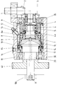
- a Drive shaft 1 is with a sheet processing machine, not shown connected. It transmits the drive movement into the bevel gears 2, 3 actual feeder drive. This is arranged in a housing 30.
- the Drive motion is initiated via the bevel gear 3 in the drive.
- the Bevel gear 3 is connected to a bell-shaped coupling half 4.
- the Coupling half 4 is by means of a roller bearing 5 on a pin 6 one Output shaft 20 arranged.
- the coupling half 4 is on its inner end face provided with locking openings 4a.
- Opposite the coupling half 4 is one second coupling half 8.
- Driving balls 8a used.
- Compared to the output shaft 20 is the Coupling half 8 mounted on a coupling ring 7.
- the coupling ring 7 is in the form of a pneumatic cylinder on the output shaft 20 a second shaft shoulder 9 mounted longitudinally.
- For air supply of the pneumatic system is an air supply 11 inside the output shaft 20 provided and passed through cross holes in the seat of the shaft shoulder 9.
- the driving coupling of the second coupling half 8 compared to the Output shaft 20 takes place via a spline 10, which is a longitudinal displacement this coupling half 8 allows.
- a sensor 12 is directed onto a shoulder surface of the second coupling half 8, which determines the position of the coupling half 8.
- the zero position or The idle position of the entire clutch arrangement is determined by a spring 13 ensured that the second coupling half 8 in the rest position out of contact from the first coupling half 4.
- a brake is arranged axially following the clutch 4, 8.
- the brake consists of a brake ring 14 and a brake pad 15. Both are conical shaped and form a conical braking surface.
- the brake ring 14 acts again as a pneumatic cylinder within the housing 30 and is via a Air connection 16 operated.
- the air connection 16 opens onto a shoulder of the Brake ring 14.
- the brake ring 14 is by means of a locking pin 17 to the Housing 30 axially displaceable, but coupled against rotation.
- springs 18 are provided which are supported on the housing and the brake ring 14 keep out of contact with the brake pad 15 at rest.
- the output shaft 20 is finally mounted in the housing 30 by means of a further roller bearing 19.
- the output gear 40 is then connected to the actual feeder drive.
- the output shaft 20 is finally coupled in the feeder housing 50.
- the function is as follows: When no air is applied, the clutch 4, 8 is disconnected and the brake 14, 15 is open. The drive shaft 1 thus runs through empty without influencing the transmission in any way, since the coupling half 4 can rotate freely on the output shaft 20. By applying air to the connection 11, the second coupling half 8 is axially displaced and the coupling balls 8a couple on the first coupling half 4 into the driving openings 4a. This creates a through drive from the drive shaft 1 via the coupling halves 4, 8 and the spline 10 to the output shaft 20. For monitoring purposes, the position is detected by the sensor 12 when the clutch 4, 8 is engaged.
- the brakes 14, 15 can be engaged by means of pneumatic actuation at the air connection 16 by means of pneumatic actuation by means of pneumatic operation.
- the brake 14, 15 acts directly on the output shaft 20 and thus detects the movement of the feeder in the fastest way.
- the relative position of the drive shaft 1 and the output shaft 20 to one another is ensured by the type of clutch 4, 8.
- the clutch balls 8a engage the clutch 4, 8 in a predetermined position and thus specify the position between the input and output.
Landscapes
- Engineering & Computer Science (AREA)
- Mechanical Engineering (AREA)
- Hydraulic Clutches, Magnetic Clutches, Fluid Clutches, And Fluid Joints (AREA)
- Sheets, Magazines, And Separation Thereof (AREA)
- Bearings For Parts Moving Linearly (AREA)
- Valve Device For Special Equipments (AREA)
Applications Claiming Priority (2)
| Application Number | Priority Date | Filing Date | Title |
|---|---|---|---|
| DE29801140U | 1998-01-24 | ||
| DE29801140U DE29801140U1 (de) | 1998-01-24 | 1998-01-24 | Anlegerantrieb |
Publications (3)
| Publication Number | Publication Date |
|---|---|
| EP0933202A2 true EP0933202A2 (fr) | 1999-08-04 |
| EP0933202A3 EP0933202A3 (fr) | 2000-03-29 |
| EP0933202B1 EP0933202B1 (fr) | 2002-07-24 |
Family
ID=8051670
Family Applications (1)
| Application Number | Title | Priority Date | Filing Date |
|---|---|---|---|
| EP98123782A Expired - Lifetime EP0933202B1 (fr) | 1998-01-24 | 1998-12-15 | Entraínement d'un appareil de marge |
Country Status (3)
| Country | Link |
|---|---|
| EP (1) | EP0933202B1 (fr) |
| AT (1) | ATE220993T1 (fr) |
| DE (1) | DE29801140U1 (fr) |
Cited By (1)
| Publication number | Priority date | Publication date | Assignee | Title |
|---|---|---|---|---|
| DE10040070A1 (de) * | 2000-08-16 | 2002-02-28 | Roland Man Druckmasch | Antrieb für einen Bogenanleger |
Families Citing this family (1)
| Publication number | Priority date | Publication date | Assignee | Title |
|---|---|---|---|---|
| DE102005029934A1 (de) * | 2005-06-28 | 2007-01-04 | Man Roland Druckmaschinen Ag | Kupplungsanordnung für eine Druckmaschine |
Family Cites Families (5)
| Publication number | Priority date | Publication date | Assignee | Title |
|---|---|---|---|---|
| DE2335781C2 (de) * | 1973-07-13 | 1982-03-18 | Horton Manufacturing Co. Inc., Minneapolis, Minn. | Kupplung |
| DD277446A1 (de) * | 1988-12-02 | 1990-04-04 | Polygraph Leipzig | Einrichtung zur drehwinkelgerechten zuschaltung eines bogenanlegers an eine druckmaschine |
| DE4102472A1 (de) * | 1991-01-20 | 1992-08-06 | Heidelberger Druckmasch Ag | Rotationsdruckmaschine zur verarbeitung von bogen |
| DE29515803U1 (de) * | 1995-10-05 | 1995-12-07 | Kba-Planeta Ag, 01445 Radebeul | Antrieb von Steuerwellen für Funktionsgruppen |
| DE19537421C1 (de) * | 1995-10-07 | 1997-03-27 | Koenig & Bauer Albert Ag | Verfahren und Vorrichtung zum Ankuppeln eines Zylinders |
-
1998
- 1998-01-24 DE DE29801140U patent/DE29801140U1/de not_active Expired - Lifetime
- 1998-12-15 AT AT98123782T patent/ATE220993T1/de not_active IP Right Cessation
- 1998-12-15 EP EP98123782A patent/EP0933202B1/fr not_active Expired - Lifetime
Cited By (2)
| Publication number | Priority date | Publication date | Assignee | Title |
|---|---|---|---|---|
| DE10040070A1 (de) * | 2000-08-16 | 2002-02-28 | Roland Man Druckmasch | Antrieb für einen Bogenanleger |
| DE10040070B4 (de) * | 2000-08-16 | 2009-02-26 | Manroland Ag | Antrieb für einen Bogenanleger |
Also Published As
| Publication number | Publication date |
|---|---|
| DE29801140U1 (de) | 1998-03-12 |
| EP0933202A3 (fr) | 2000-03-29 |
| ATE220993T1 (de) | 2002-08-15 |
| EP0933202B1 (fr) | 2002-07-24 |
Similar Documents
| Publication | Publication Date | Title |
|---|---|---|
| DE19708968B4 (de) | Differential für ein Kraftfahrzeug | |
| EP0741015B1 (fr) | Dispositif pour régler la position circonférentielle et latérale du cylindre porte-plaque | |
| DE19539627B4 (de) | Kraftantriebseinheit für Flugzeugfrachtbeförderungssysteme | |
| DE102021131440B4 (de) | Elektromagnetisch zuschaltbare Differentialbaugruppe | |
| DE102018203529B4 (de) | Betätigung und Steuerung einer Differentialsperre | |
| EP0997273B1 (fr) | Groupe imprimant d'une presse à bobines | |
| DE19721091A1 (de) | Zweistellungs-Antriebstrenneinrichtungen für Fahrzeuge | |
| DE19852438A1 (de) | Druckwerk für eine Rollenrotationsdruckmaschine | |
| DE3931618A1 (de) | Zu- oder abschaltbare viskosekupplung | |
| DE4110035C2 (de) | Vorrichtung zum Verstellen von Elementen in Falzwerkzylindern von Rotationsdruckmaschinen | |
| DE3830200C1 (fr) | ||
| EP0521268B1 (fr) | Accouplement à surcharge | |
| DE4106203C2 (de) | Kraftübertragungssystem | |
| DE2613065B2 (de) | Automatische kupplungsvorrichtung fuer ein handrad | |
| DE4027209C1 (fr) | ||
| WO2023021086A1 (fr) | Ensemble embrayage pour un différentiel d'un véhicule à moteur | |
| EP1109695B1 (fr) | Dispositif de commande servant a regler des elements d'equipement appartenant a un vehicule automobile | |
| DE69808593T2 (de) | Verstelleinrichtung für ein stufenloses getriebe | |
| DE3822518C2 (fr) | ||
| EP0933202B1 (fr) | Entraínement d'un appareil de marge | |
| DE2612628A1 (de) | Hilfs- oder notantrieb fuer ein motorisch angetriebenes rolltor | |
| DE10223224B4 (de) | Gangwechselvorrichtung für Fahrzeuggetriebe | |
| DE2363080A1 (de) | Einrichtung zur lenkung eines kraftfahrzeuges | |
| DE69009565T2 (de) | Differentialgetriebe. | |
| DE102022202313B4 (de) | Differentialgetriebevorrichtung für ein Kraftfahrzeug zum Ankoppeln und Abkoppeln von Freiläufen |
Legal Events
| Date | Code | Title | Description |
|---|---|---|---|
| PUAI | Public reference made under article 153(3) epc to a published international application that has entered the european phase |
Free format text: ORIGINAL CODE: 0009012 |
|
| AK | Designated contracting states |
Kind code of ref document: A2 Designated state(s): AT CH FR GB LI |
|
| AX | Request for extension of the european patent |
Free format text: AL;LT;LV;MK;RO;SI |
|
| PUAL | Search report despatched |
Free format text: ORIGINAL CODE: 0009013 |
|
| AK | Designated contracting states |
Kind code of ref document: A3 Designated state(s): AT BE CH CY DE DK ES FI FR GB GR IE IT LI LU MC NL PT SE |
|
| AX | Request for extension of the european patent |
Free format text: AL;LT;LV;MK;RO;SI |
|
| 17P | Request for examination filed |
Effective date: 20000225 |
|
| AKX | Designation fees paid |
Free format text: AT CH FR GB LI |
|
| 17Q | First examination report despatched |
Effective date: 20001106 |
|
| REG | Reference to a national code |
Ref country code: DE Ref legal event code: 8566 |
|
| GRAG | Despatch of communication of intention to grant |
Free format text: ORIGINAL CODE: EPIDOS AGRA |
|
| GRAG | Despatch of communication of intention to grant |
Free format text: ORIGINAL CODE: EPIDOS AGRA |
|
| GRAH | Despatch of communication of intention to grant a patent |
Free format text: ORIGINAL CODE: EPIDOS IGRA |
|
| GRAH | Despatch of communication of intention to grant a patent |
Free format text: ORIGINAL CODE: EPIDOS IGRA |
|
| GRAA | (expected) grant |
Free format text: ORIGINAL CODE: 0009210 |
|
| AK | Designated contracting states |
Kind code of ref document: B1 Designated state(s): AT CH FR GB LI |
|
| REF | Corresponds to: |
Ref document number: 220993 Country of ref document: AT Date of ref document: 20020815 Kind code of ref document: T |
|
| REG | Reference to a national code |
Ref country code: GB Ref legal event code: FG4D Free format text: NOT ENGLISH |
|
| REG | Reference to a national code |
Ref country code: CH Ref legal event code: EP |
|
| GBT | Gb: translation of ep patent filed (gb section 77(6)(a)/1977) |
Effective date: 20020724 |
|
| REG | Reference to a national code |
Ref country code: CH Ref legal event code: NV Representative=s name: E. BLUM & CO. PATENTANWAELTE |
|
| PGFP | Annual fee paid to national office [announced via postgrant information from national office to epo] |
Ref country code: CH Payment date: 20021119 Year of fee payment: 5 |
|
| PGFP | Annual fee paid to national office [announced via postgrant information from national office to epo] |
Ref country code: GB Payment date: 20021128 Year of fee payment: 5 |
|
| PGFP | Annual fee paid to national office [announced via postgrant information from national office to epo] |
Ref country code: FR Payment date: 20021206 Year of fee payment: 5 |
|
| PLBE | No opposition filed within time limit |
Free format text: ORIGINAL CODE: 0009261 |
|
| STAA | Information on the status of an ep patent application or granted ep patent |
Free format text: STATUS: NO OPPOSITION FILED WITHIN TIME LIMIT |
|
| 26N | No opposition filed |
Effective date: 20030425 |
|
| PG25 | Lapsed in a contracting state [announced via postgrant information from national office to epo] |
Ref country code: GB Free format text: LAPSE BECAUSE OF NON-PAYMENT OF DUE FEES Effective date: 20031215 |
|
| PG25 | Lapsed in a contracting state [announced via postgrant information from national office to epo] |
Ref country code: LI Free format text: LAPSE BECAUSE OF NON-PAYMENT OF DUE FEES Effective date: 20031231 Ref country code: CH Free format text: LAPSE BECAUSE OF NON-PAYMENT OF DUE FEES Effective date: 20031231 |
|
| GBPC | Gb: european patent ceased through non-payment of renewal fee |
Effective date: 20031215 |
|
| REG | Reference to a national code |
Ref country code: CH Ref legal event code: PL |
|
| PG25 | Lapsed in a contracting state [announced via postgrant information from national office to epo] |
Ref country code: FR Free format text: LAPSE BECAUSE OF NON-PAYMENT OF DUE FEES Effective date: 20040831 |
|
| REG | Reference to a national code |
Ref country code: FR Ref legal event code: ST |
|
| PGFP | Annual fee paid to national office [announced via postgrant information from national office to epo] |
Ref country code: AT Payment date: 20061213 Year of fee payment: 9 |
|
| PG25 | Lapsed in a contracting state [announced via postgrant information from national office to epo] |
Ref country code: AT Free format text: LAPSE BECAUSE OF NON-PAYMENT OF DUE FEES Effective date: 20071215 |