EP0933221B1 - Appareil d'enregistrement, méthode d'enregistrement, et moyen de stockage - Google Patents
Appareil d'enregistrement, méthode d'enregistrement, et moyen de stockage Download PDFInfo
- Publication number
- EP0933221B1 EP0933221B1 EP99300666A EP99300666A EP0933221B1 EP 0933221 B1 EP0933221 B1 EP 0933221B1 EP 99300666 A EP99300666 A EP 99300666A EP 99300666 A EP99300666 A EP 99300666A EP 0933221 B1 EP0933221 B1 EP 0933221B1
- Authority
- EP
- European Patent Office
- Prior art keywords
- recording
- size
- sheet
- recording medium
- ink
- Prior art date
- Legal status (The legal status is an assumption and is not a legal conclusion. Google has not performed a legal analysis and makes no representation as to the accuracy of the status listed.)
- Expired - Lifetime
Links
- 238000000034 method Methods 0.000 title claims description 58
- 230000008569 process Effects 0.000 claims description 25
- 239000003086 colorant Substances 0.000 claims description 9
- 230000008859 change Effects 0.000 claims description 3
- 238000005549 size reduction Methods 0.000 claims 2
- 238000011946 reduction process Methods 0.000 claims 1
- 238000001514 detection method Methods 0.000 description 24
- 238000000859 sublimation Methods 0.000 description 5
- 230000008022 sublimation Effects 0.000 description 5
- 230000000994 depressogenic effect Effects 0.000 description 4
- 230000015572 biosynthetic process Effects 0.000 description 3
- 230000004927 fusion Effects 0.000 description 3
- 230000000977 initiatory effect Effects 0.000 description 3
- 238000004519 manufacturing process Methods 0.000 description 3
- 230000009467 reduction Effects 0.000 description 3
- XEEYBQQBJWHFJM-UHFFFAOYSA-N Iron Chemical compound [Fe] XEEYBQQBJWHFJM-UHFFFAOYSA-N 0.000 description 2
- 238000010586 diagram Methods 0.000 description 2
- 238000001454 recorded image Methods 0.000 description 2
- GGCZERPQGJTIQP-UHFFFAOYSA-N sodium;9,10-dioxoanthracene-2-sulfonic acid Chemical compound [Na+].C1=CC=C2C(=O)C3=CC(S(=O)(=O)O)=CC=C3C(=O)C2=C1 GGCZERPQGJTIQP-UHFFFAOYSA-N 0.000 description 2
- 230000002194 synthesizing effect Effects 0.000 description 2
- 239000000853 adhesive Substances 0.000 description 1
- 239000012790 adhesive layer Substances 0.000 description 1
- 230000003466 anti-cipated effect Effects 0.000 description 1
- 230000004397 blinking Effects 0.000 description 1
- 238000006243 chemical reaction Methods 0.000 description 1
- 239000000470 constituent Substances 0.000 description 1
- 230000000881 depressing effect Effects 0.000 description 1
- 238000007599 discharging Methods 0.000 description 1
- 230000000694 effects Effects 0.000 description 1
- 230000006870 function Effects 0.000 description 1
- 238000010438 heat treatment Methods 0.000 description 1
- 229910052742 iron Inorganic materials 0.000 description 1
- 230000004048 modification Effects 0.000 description 1
- 238000012986 modification Methods 0.000 description 1
- 238000010186 staining Methods 0.000 description 1
Images

Classifications
-
- B—PERFORMING OPERATIONS; TRANSPORTING
- B41—PRINTING; LINING MACHINES; TYPEWRITERS; STAMPS
- B41J—TYPEWRITERS; SELECTIVE PRINTING MECHANISMS, i.e. MECHANISMS PRINTING OTHERWISE THAN FROM A FORME; CORRECTION OF TYPOGRAPHICAL ERRORS
- B41J2/00—Typewriters or selective printing mechanisms characterised by the printing or marking process for which they are designed
- B41J2/315—Typewriters or selective printing mechanisms characterised by the printing or marking process for which they are designed characterised by selective application of heat to a heat sensitive printing or impression-transfer material
- B41J2/32—Typewriters or selective printing mechanisms characterised by the printing or marking process for which they are designed characterised by selective application of heat to a heat sensitive printing or impression-transfer material using thermal heads
- B41J2/325—Typewriters or selective printing mechanisms characterised by the printing or marking process for which they are designed characterised by selective application of heat to a heat sensitive printing or impression-transfer material using thermal heads by selective transfer of ink from ink carrier, e.g. from ink ribbon or sheet
Definitions
- the present invention relates to a recording apparatus for recording by driving a recording head to transfer ink from an ink sheet carrying sequential colours to a recording medium in accordance with image data, the apparatus being capable of recording on a plurality of different sizes of recording media and being capable of using plural ink sheets corresponding to the different sizes of recording media, as well as to relate to a recording method and a storage medium therefore.
- thermo transfer methods As recording methods of color images, there have been known various ones, among some others, such as the ink jet method for recording by discharging ink, the electronic photographing method for forming images by use of toner, the thermal transfer method for transferring ink to a recording medium by the application of thermal energy with an ink sheet having ink coated on it. Also, of the thermal transfer methods, there have been known a thermal fusion type that uses an ink sheet coated with ink which is fused when heat is applied, and a thermal sublimation type that uses an ink sheet coated with ink which is sublimated when heat is applied, and so on.
- the recording apparatus that adopts the thermal transfer method using the ink sheet makes it easier to maintain the apparatus.
- the sublimation type transfer method facilitates the formation of full color images of the higher quality which is equal to that of a silver salt photography.
- this method is suitable for a recording apparatus that records on a recording sheet of comparatively small size.
- the recording sheet of comparatively small size is mainly used often.
- the output images should desirably be recorded in the higher quality equal to that of a silver salt photography.
- the aforesaid thermal transfer type recording apparatus is anticipated to function as a color printer adoptable as output means of the video camera, digital camera, or the like.
- the recording sheets are housed in a sheet feed cassette or set in a sheet feed unit of the thermal transfer type recording apparatus. Then, each of the recording sheets is picked up by the rotation of a sheet feed roller to carry it to the recording unit.
- the thermal head installed in the recording unit is driven with respect to the recording sheet thus carried to this unit in a state where the thermal head is pressed to the platen through the ink sheet and the recording sheet as well. In this way, the ink which is coated on the ink sheet is transferred to the recording sheet for recording images on it.
- the sizes of images to be recorded, the sizes of recording sheets on which the images should be output, and the kinds of recording sheets to be used for recording may differ variously. Therefore, it is desired to provide a recording apparatus capable of recording on various sizes and kinds of recording sheets as the case may be.
- thermal transfer type recording apparatus it is generally practiced to use ink sheet having ink of plural colors coated on each of them sequentially for recording a color image. Then, there has been known a method whereby to arrange the area on which ink of each color is coated corresponding to the size of a recording sheet to be used, hence preventing the wasteful consumption of ink sheets.
- the user should select the size of a recording sheet and set on a recording apparatus the ink sheet which corresponds to the size of that particular recording sheet used for recording when he intends to output an image in a desired size using such recording apparatus that may be able to deal with a plurality of recording sheets of different sizes.
- the recording apparatus For the recording apparatus that may be able to deal with a plurality of recording sheets of different sizes, it is generally known to select a recording sheet and execute the recording control in accordance with the size of recording sheet thus selected by the designation which is made by the user through his key entry or the like. However, if the user inputs an erroneous designation or forget inputting designation, the resultant recording is not made on the recording sheet as he has intended. Thus, the recording sheets are wastefully used after all. Particularly, for the aforesaid thermal sublimation type recording apparatus, it is usual to adopt recording sheets dedicated for its use in order to attain the higher quality recording. As compared with an ordinary sheet, this specially treated recording sheet is expensive, and it costs the user more if the recording sheets are wastefully used.
- a recording apparatus capable of recording on a recording sheet (hereinafter referred to as a seal sheet) having a adhesive layer on it.
- the recording sheet is peeled off from the base sheet to make its adhesion to some other object possible so that the recorded image can be used as a seal.
- the user may wrongly select the kind of recording sheet to be used or wrongly execute the edit or the process or he may execute recording without recognizing the kind of recording sheets stored in a sheet feed cassette that supplies recording sheets.
- some other images which are not suitable for the seal formation, may be recorded while seal sheets are stored in the sheet feed cassette or a larger image may be recorded against a perforated seal sheet.
- the seal sheets which are more expensive than ordinary sheets are consumed wastefully after all.
- US-A-5432532 describes a video printer for printing a plurality of kinds of images of different image formats by transferring ink from an ink sheet carrying sequential colors to a recording medium in accordance with image data, wherein the video printer includes an ink decision unit which determines the length and type of ink sheet and an image printing sheet decision unit which determines the length of printing sheet.
- a system controller determines the type of printing to be carried out on the basis of this information, for example the system controller determines whether the image data should be expanded or compressed to fit the printing sheet.
- the present invention provides a recording apparatus as set out in claim 1.
- the present invention provides a method of recording as set out in claim 12.
- An embodiment of the invention provides a recording apparatus capable of recording without recording improperly any smaller images that may be unfit for the size of the recording sheet or staining the platen even when the recording medium and the ink sheet installed thereon are different in its sizes or the user does not designate the size of the recording medium to be used, and a recording method and a storage medium therefor.
- the present invention is not necessarily limited to the recording apparatus, but it may be possible to implement the invention by a recording method, and further, in the form of a storage medium, such as a CD-ROM or a floppy disc. Example not falling within the scope of the claims
- This example is arranged to provide a recording apparatus capable of executing the recording operation appropriately without recording an image whose size is made improperly larger than the recording sheet even when the size of the recording sheet used for recording and the size of the corresponding ink sheet are different, and also, this example provides a recording method therefor.
- Fig. 1 is a cross-sectional view which shows the principal structure of a recording apparatus in accordance with this example.
- each one of recording sheets P is carried separately from a sheet cassette 2 having the recording sheets P stored in it to a apparatus main body 1 by means of a sheet feed roller 3.
- the recording sheet P is pinched by a pair of carrier rollers 4 to make its reciprocation possible to and from the recording unit.
- a platen roller 5 and a thermal head 6 which gives heat in accordance with recording information are arranged to face each other with the carrier path of the recording sheet between them.
- each of ink sheets 8 having thermal fusion or thermal sublimation ink coated on them which are stored in an ink sheet cassette (may be referred to as an ink cassette) 7, is pressed to the recording sheet P by means of the thermal head 6.
- the heat generating devices of the thermal head 6 are selectively heated to record the required images on the recording sheet P.
- each ink portion of yellow (Y), magenta (M), and cyan (C) is coated sequentially on the ink sheet 8 substantially in the same size as the recording sheet P shown in Fig. 2B.
- the recording sheet P is returned to a position P1 where the recording is initiated.
- each of the recording sheets P stored in the sheet cassette 2 is, as shown in Fig. 2B, in the A-7 size which is approximately a half of A-6 size recording sheet Ps shown in Fig. 2D.
- the position (indicated by solid lines) before recording in the case of the A-6 size (indicated by solid lines), and the position immediately after the recording (indicated by broken lines) are also represented in Fig. 1.
- Fig. 2B shows the recording sheet P of A-7 size.
- Fig. 2D shows the recording sheet Ps of A-6 size. Therefore, the recording sheet P shown in Fig. 2B has a size which is a half the recording sheet Ps as shown in 2D.
- the recording sheet Ps may also be referred to as the standard size, while the recording sheet P as the half size.
- Fig. 2A shows an ink sheet that corresponds to the recording sheet P of A-7 size shown in Fig. 2B.
- Fig.. 2C shows an ink sheet that corresponds to the recording sheet Ps of A-6 size shown in Fig. 2D.
- the recording apparatus shown in Fig. 1 is provided with a sensor 10 to discriminate the kinds of the ink sheet cassettes.
- the recording sheets it is more reliable fundamentally if the sheet cassettes are arranged each per sheet size, thus making the discrimination easier.
- Fig. 1 there is no representation of the detection sensor for the size of each recording sheet.
- the detection sensor for the size of each recording sheet.
- the user forgets setting the guide plate 11 when he sets the recording sheets of A-7 size, which is a half the size of the standard sheet, there is the problem of erroneous recognition that the ink sheet cassette for the A-6 standard size has been set.
- the recording sheet is carried provisionally to the position P1 for initiating the current recording, the length of the recording sheet in use can be measured by measuring the time or the like required for the recording sheet to pass a leading end detection sensor 14. Therefore, it is possible to discriminate the difference of the size of the ink sheet cassette for the A-7 recording sheet and exhaust the recording sheet immediately, thus avoiding the erroneous recording.
- the image control unit comprises means 15 for detecting an ink sheet cassette; means 16 for detecting the size of a recording sheet; a buffer memory 17; an image processing unit 18 for executing the reduction or enlargement of an image, the rotation thereof, or the like; a thermal head 19; a thermal control unit 20 therefor; a carrier motor 21; and a driving control pulse generation unit 22.
- the inputted image can be edited to provide an image form having the optimal size and direction for recording without any particular entry of the size of the recording sheet for the current recording, because both the kinds of the recording sheet and ink sheet cassette currently installed on the recording apparatus can be determined by the output contents of the detection means 15 and 16.
- the intended recording is executed as it is if the size of the recording sheet is as shown in Fig. 2D, and the size of the ink sheet is as shown in Fig. 2C, which indicates that both of them are of the A-6 size identically.
- the combination of the recording sheet and ink sheet is such as those shown in Fig. 2B and Fig. 2C or Fig. 2D and Fig. 2A, which indicates that either one of them is different at least with respect to the size or the direction, a warning is issued or an error message is indicated, hence prohibiting the execution of recording process.
- the recording apparatus automatically resizes (modification of image size) and changes the direction of recording (executes the image rotation process) in accordance with information from the recording size detection means 16 based on the image information of the A-6 size.
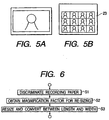
- step S1 the recording sheets are discriminated in step S1.
- the recording sheets usable for the recording apparatus shown in Fig. 1 are not necessarily limited to the paper sheets whose sizes are different as shown in Fig. 2B and Fig. 2D, but the transfer sheet is also useable, with which an image can be transferred to some other medium by use of a heating equipment such as an iron.
- a heating equipment such as an iron.
- the recording sheet discrimination in the step S1 it is determined whether the size is A-7 like the recording sheet P shown in Fig. 2B or A-6 like the recording sheet P, shown in Fig. 2D. At the same time, it is determined whether or not the current sheet is a transfer sheet. Also, for the transfer sheet, it is determined whether it is of the A-6 size or of the A-7 size.
- the discrimination of the recording sheets is possible by use of the sheet feed cassettes 2 as to the sizes thereof.
- the discrimination of whether it is an ordinary sheet or a transfer sheet is possible in accordance with the user's key entry through an operation unit (not shown).
- the method of recording sheet determination is not necessarily limited to those described above. It may be possible to arrange the structure so that both the sizes and kinds of recording sheets are determined in accordance with the designation made by the user.
- a flag flg_sheet is set as given below to indicate the kind and size of the recording sheet.
- Ordinary sheet of A-6 size flg_sheet 0
- step S2 the process is executed to obtain the enlargement (reduction) factor h in the resizing process whereby to modify the size of an image.
- the description will be made of a case where the size is modified so that no image is made larger than the recording sheet currently in use for any one of images irrespective of its aspect ratio.
- the enlargement (reduction) factor h in the resizing process is arranged to adopt the pixel numbers required for recording, as well as the smaller factor of the respective ratios of the sizes in the length and the breadth of the original image.
- h (the smaller one of M1/m and L/n)
- h (the smaller one of M2/n and L/m)
- step S3 the resizing process, and the image rotation process whereby to convert the length and breadth of the image are executed.
- the pixel position of the original image is indicated by the (x, y)
- the pixel position of the resized image is indicated by the (X, Y).
- the value of the position (x, y) of the original image is defined as f(x, y)
- the value of the position (X, Y) of the resized image is defined as g(X, Y).
- a recording sheet such as a seal sheet having half perforations 23 as shown in Fig. 5A
- the A-7 size as shown in Fig. 5A so that such recording sheet is arranged to be a (specific) size which is dedicated for the intended use, and then, such dedicated size is arranged to be detectable by use of the detection means 16 or the leading end detection sensor 14.
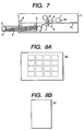
- Fig. 7 is a cross-sectional view which shows the structure of a recording apparatus which is applicable to the present embodiment.
- the same reference numerals are applied to the same constituents shown in Fig. 1.
- the entire structure of the recording apparatus will be described.
- Each one of the recording sheets P is carried separately from the sheet cassette 2 having the recording sheets P stored in it to the apparatus main body 1 by means of the sheet feed roller 3.
- the recording sheet is pinched by a pair of the carrier rollers 4 to make its reciprocation possible to and from the recording unit.
- the platen roller 5 and the thermal head 6 which gives heat in accordance with recording information are arranged to face each other with the carrier path of the recording sheet between them.
- the heat generating devices of the thermal head 6 are selectively heated to transfer and record the required images on the recording sheet P.
- the ink sheet 8 which has been described earlier is such that each ink portion of yellow (Y), magenta (M), and cyan (C) is coated sequentially almost in the same size as the recording sheet P.
- the recording sheet P is returned to the position P1 where the recording is initiated.
- recording is made one after another by the ink portion corresponding to each color.
- the recording sheet P reciprocates by means of the pair of the carrier rollers 4 in the same numbers as those of colors. Lastly, the recording sheet is guided to a pair of the exhaust rollers 9 to be exhausted outside of the housing, hence completing the current recording.
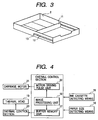
- the recording sheets P stored in the cassette 2 vary such as the A-6 size (postcard size) as shown in Fig. 8A, the A-7 size which is approximately a half thereof as shown in Fig. 8B, and the panorama size (not shown) whose length is two times the length of the one shown in Fig. 8A.
- the recording apparatus shown in Fig. 7 is provided with the sensor 10 to discriminate the kinds of the ink sheet cassettes 7.
- the sheet cassettes are arranged each per sheet size, thus making the discrimination easier.
- the detection sensor for the size of each recording sheet there is no representation of the detection sensor for the size of each recording sheet.
- the user forgets setting the guide plate 11 when he sets the recording sheets of A-7 size, which is a half the size of the standard sheet a problem is encountered, provided that the ink sheet cassette for the A-6 standard size has been set.
- the recording sheet P1 is carried provisionally to the position P1 for initiating the current recording, the length of the recording sheet P in use can be measured by measuring the time or the like required for the recording sheet P to pass the leading end detection sensor 14. Therefore, it is possible to discriminate the difference of the size of the ink sheet cassette before recording is initiated and exhaust the recording sheet, thus avoiding the erroneous recording.
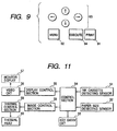
- Fig. 9 and Figs. 10A to 10C are views which illustrate the structure related to the operation unit.
- Fig. 9 shows the arrangement of operational keys.
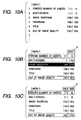
- Fig. 10 shows the editing screen.
- a print key 91 of the operational keys shown in Fig. 9 is depressed to execute it.
- a menu key 92 in Fig. 9 is depressed to call the menu screen as shown in Fig. 10A.
- selection is made by means of four arrow keys 93 shown in Fig. 9 as needed, and determined by depressing the execution key 94.
- the numeral 1 designates the setting of the "printed numbers of sheets"
- the [1] is the default setting which indicates one sheet.
- the numeral can advance beginning with 2. Then, when the desired number appears, the execution key 94 is depressed to determine the printed numbers of sheet for execution.
- the numeral 2 indicated on the menu shown in Fig. 10A designates the selection of the "multiple screen", which makes it possible to select 2 screens, 4 screens, 9 screens, or the like for the number of images to be recorded from one recording sheet. If the seal sheet, such as shown in Fig. 8A, which is divided by perforations, 16 screens can be selected to make each image usable as a seal.
- the numeral 3 designates the "image to be inlaid" which is prepared for use of superimposition in advance.
- the numeral 4 designates the selection of "panoramic image", which makes it possible to record on the panorama sheet by synthesizing a plurality of sheets having on them the images which have been continuously photographed (not shown).
- the numeral 5 designates the "title phrase” such as "A Merry Christmas” "A Happy New Year” or some other specific expression which is prepared in advance for use of superimposition for the standard postcard size.
- the numeral 6 designates the "image quality adjustment”. If this designation is selected with "yes” mark, it becomes possible to adjust the contrast, darkness of colors, or the like. These have been one example. It may be possible to provide many other selections, such as frames for use of superimposition, patterns of famous sites and landscapes, special effects or the like.
- the control system that deals with the above operations comprises an ink cassette detection sensor 51; a recording sheet size detection sensor 52; a key entry circuit 53; a control unit 54 of these sensors and circuit; a video output circuit 56; a monitor display indicator 57; an image control unit 58, a thermal head 60, and a thermal control unit 59.
- the seal sheet of the standard size coated with adhesive agent which is formed to be partly peeled off for its adhesion to some other object, is installed on the recording apparatus, while the ink cassette for A-6 seal sheet use is set as the ink cassette 7, the detection of A-6 size is made by use of the recording sheet size sensor 52, and also, the detection of the ink cassette for use of A-6 seal sheet is made by use of the ink cassette detection sensor 52. Consequently, then, the menu is indicated on the display as shown in Fig. 10B. On the menu shown in Fig. 10B, only the framed items are effective, and, for example, only such portion is indicated by solid line or by the reversed characters, while the other portions are indicated by broken line or the like to make its selections impossible.
- the multiple screen selection is restricted to the 16 screens so that the number 16 is automatically set if this is selected.
- the next item that is, the image for inlaying use, may be used for recording as it is without being superimposed in some cases, but it is mostly used for the superimposition. Therefore, the screen which is used in this respect is assumed to be the one immediately before the execution button is depressed. Also, it is arranged to display the information that indicates the seal sheet at A in Fig. 10B in accordance with the discriminating signals from the ink cassette detection sensor 51 which may sense the respective ink ribbon marks for determination as shown in Fig. 11.
- the ordinary sheet of A-6 size is set in the recording apparatus, while the ink cassette for use of ordinary sheet of A-6 size as the ink cassette 7, the A-6 size is detected by use of the recording sheet size sensor 52, and the ink cassette for use of the ordinary sheet which corresponds to the A-6 size is detected by use of the ink cassette detection sensor 51. Consequently, then, the printed numbers of sheet, the multiple screen, the title phrase, and the image quality adjustment are indicated on the menu. Thus, whereas the "title phrase" is made selective, it becomes impossible to select the "image to be inlaid", and then, the information of the "full size” is indicated at A in Fig. 10B.
- Fig. 10C shows the edit screen when the half size recording sheet, which is illustrated in Fig. 8B, is set, and also, the ink cassette for the half size use is set.
- the recording sheet since the recording sheet is small, it automatically becomes impossible to select the multiple screen, the title phrase, or the like. Only the limited items are indicated, and the information that indicates the "half size" appears at A in Fig. 10C.
- the seal sheet is mainly used as the A-6 size sheet, and the seal sheet cannot be sensed directly. Therefore, there is a drawback that the edit screen for use of sheet is not displayed even when the seal sheet is set if the ink cassette is for the use of the ordinary sheet.
- the seal sheet is detected by the recording sheet size detection sensor, and it is arranged to illuminate the item indications on the seal sheet edit screen if the seal sheet is detected by use of the ink cassette detection sensor. It may also be arranged to blink the item indications on the seal sheet edit screen to issue warning if the seal sheet is set but not the ink cassette for use of the seal sheet and vice versa. For the combination which causes this blinking, a fairly good image is still obtainable, although it is impossible to obtain the optimal one. Therefore, it may be possible to ignore such warning.
- the item indications on the edit screen may be determined depending only on the detection output of the recording sheet size detection sensor.
- the A-6 size such menu that contains the printed numbers of sheet, the multiple screen, the title phrase, the image quality adjustment is indicated on the display.
- the aforesaid menu for use of the seal sheet is indicated on it.
- the panorama size such menu that contains the printed numbers of sheet, the panorama, the title phrase, and the image quality adjustment is indicated on it.
- the menu which is represented in Fig. 10C is indicated on it, that is, the printed numbers of sheet, and the image quality adjustment.
- the present invention it is made possible to select the size of the recording sheet installed on the recording apparatus or only the items that can be edited to obtain the image mode adjust to the kind of the ink cassette without manually inputting the size of the sheet on which to record the images. Hence, it becomes easier to record the images adjusted to match the size and kind of a recording sheet.
- the present invention it is of course possible for the present invention to arrange the variations of its embodiment in accordance with various sizes of the recording sheet and the particularity of the sheet to be used.
- the recording sheet and the ink cassette are used correspondingly in a proper combination. It is, therefore, desirable to detect both the kind of the recording sheet and the size of the ink cassette in order to prevent them from being used in a wrong combination. It is of course possible to execute the operation in accordance with the result of the detection of either one of them. Since it costs more to provide detection means for both of them, the manufacture costs of the apparatus can be suppressed by the implementation of the present invention with only one of the detection means.
Landscapes
- Electronic Switches (AREA)
- Impression-Transfer Materials And Handling Thereof (AREA)
Claims (23)
- Appareil d'enregistrement destiné à enregistrer en attaquant une tête d'enregistrement (6) afin de transférer une encre d'une feuille encreuse (8) portant des couleurs successives à un support d'enregistrement (P) conformément à des données d'image, l'appareil étant capable d'enregistrer sur plusieurs formats différents de supports d'enregistrement et étant capable d'utiliser plusieurs feuilles encreuses correspondant aux différents formats de support d'enregistrement, l'appareil comportant :un moyen (2) de transport de support d'enregistrement destiné à transporter le support d'enregistrement ;un moyen (7) de transport de feuille encreuse destiné à transporter la feuille encreuse ;un moyen (51, 52, 54) de détermination destiné à déterminer au moins l'un du format du support d'enregistrement (P) devant être utilisé pour l'enregistrement et du format du support d'enregistrement correspondant à la feuille encreuse (8) devant être utilisée pour l'enregistrement ;caractérisé par
un moyen de sortie (56) destiné à délivrer en sortie à un afficheur (57) une information pour indiquer à l'utilisateur les options d'enregistrement disponibles pour une opération d'enregistrement ; et
un moyen de commande (54, 55) destiné à commander l'information d'option d'enregistrement délivrée en sortie par le moyen de sortie (56) conformément au résultat de la détermination par le moyen de détermination (51, 52, 54) afin de commander le moyen de sortie (56) pour amener l'afficheur à indiquer en tant qu'options d'enregistrement disponibles les options d'enregistrement qui correspondent au, au moins un, du format du support d'enregistrement et du format du support d'enregistrement correspondant à la feuille encreuse déterminée par le moyen de détermination (51, 52, 54). - Appareil d'enregistrement selon la revendication 1, dans lequel le moyen de sortie (56) peut être mis en oeuvre pour délivrer en sortie le contenu devant être indiqué sur un moyen d'indication de l'équipement connecté extérieurement à l'appareil d'enregistrement, et le moyen de sortie (56) peut être mis en oeuvre pour délivrer en sortie une information pour afficher un écran d'édition concernant le contenu de l'opération, sur le moyen d'indication.
- Appareil d'enregistrement selon la revendication 1 ou 2, comportant en outre : un moyen destiné à détecter la longueur du support d'enregistrement dans la direction de transport du moyen de transport, dans lequel le moyen de détermination (51, 52, 54) peut être mis en oeuvre pour déterminer le format du support d'enregistrement conformément à la longueur détectée du support d'enregistrement.
- Appareil d'enregistrement selon la revendication 1 ou 2, dans lequel le moyen (2) de transport du support d'enregistrement comporte une unité d'alimentation en feuilles destinée à contenir le support d'enregistrement, l'unité d'alimentation en feuilles étant pourvue d'un élément mobile (11) pouvant être déplacé par un utilisateur jusqu'à une position correspondant au format du support d'enregistrement (P) devant être contenu, et dans lequel le moyen de détermination (51, 52, 54) peut être mis en oeuvre pour déterminer le format du support d'enregistrement (P) en fonction de la position de l'élément mobile.
- Appareil d'enregistrement selon la revendication 4, dans lequel l'unité (2) d'alimentation en feuilles d'enregistrement se présente sous la forme d'une cassette pouvant être montée de façon amovible sur l'appareil d'enregistrement.
- Appareil d'enregistrement selon l'une quelconque des revendications précédentes, dans lequel chaque zone de la région revêtue d'une encre de chaque couleur parmi les multiples feuilles encreuses est différente suivant le format du support d'enregistrement qui lui correspond.
- Appareil d'enregistrement selon l'une quelconque des revendications précédentes, dans lequel le moyen de transport de feuille encreuse se présente sous la forme d'une cassette pour feuilles encreuses contenant des feuilles encreuses (8) et est agencé de façon à pouvoir être monté de manière amovible sur le support d'enregistrement, et le moyen de détermination (51, 52, 54) peut être mis en oeuvre pour déterminer le format de la feuille encreuse en fonction de l'état de la cassette pour feuilles encreuses.
- Appareil d'enregistrement selon l'une quelconque des revendications précédentes, comportant en outre : un moyen de traitement de données d'image destiné à traiter des données d'image pour exécuter un processus d'édition sur les données d'image, le moyen de traitement de données d'image pouvant être mis en oeuvre pour agencer plusieurs images traitées par un processus de réduction de format d'image, le moyen de commande (54, 55) pouvant être mise en oeuvre pour commander la sortie du moyen de sortie (56) afin d'indiquer le contenu pour exécuter l'opération d'enregistrement en agençant plusieurs fois la même image sur le support d'enregistrement en utilisant le moyen de traitement de données d'image lorsque le format du support d'enregistrement déterminé (P) ou du support d'enregistrement correspondant à la feuille encreuse déterminée (8) est un format spécifique.
- Appareil d'enregistrement selon l'une quelconque des revendications précédentes, comprenant en outre la feuille encreuse et dans lequel l'encre revêtant la feuille encreuse a pour propriété d'être sublimée lorsque de l'énergie électrique est appliquée.
- Appareil d'enregistrement selon l'une quelconque des revendications 1 à 8, comportant en outre la feuille encreuse et dans lequel l'encre revêtant la feuille encreuse a pour propriété de fondre lorsque de l'énergie électrique est appliquée.
- Appareil d'enregistrement selon l'une quelconque des revendications précédentes, dans lequel les options comprennent une pluralité de points correspondants à différents processus respectifs d'édition, et le moyen de commande (54, 55) peut être mis en oeuvre afin d'amener un ou plusieurs de la pluralité de points d'édition à pouvoir être sélectionnés afin que seule une opération d'édition ou des opérations d'édition convenant au format déterminé du support d'enregistrement et au type du moyen (7) de transport de feuille encreuse soient autorisées, et pour rendre l'indication pour des points pouvant être sélectionnés différente de l'indication pour des points ne pouvant pas être sélectionnés.
- Procédé d'enregistrement utilisant un appareil d'enregistrement qui est capable d'enregistrer sur plusieurs formats différents de support d'enregistrement et d'utiliser plusieurs feuilles encreuses correspondant aux différents formats de support d'enregistrement et est pourvu d'un moyen (2) de transport de support d'enregistrement transportant un support d'enregistrement (P), d'un moyen de transport de feuille encreuse transportant une feuille encreuse (8) portant en revêtement une encre de plusieurs couleurs successives, et d'une tête d'enregistrement (6) destinée à transférer de l'encre de la feuille encreuse au support d'enregistrement conformément à des données d'image, le procédé d'enregistrement comprenant les étapes qui consistent :à déterminer au moins l'un du format du support d'enregistrement (P) devant être utilisé pour un enregistrement et du format du support d'enregistrement correspondant à la feuille encreuse (8) devant être utilisée pour l'enregistrement; et caractérisé par les étapes qui consistentà délivrer en sortie à un afficheur (57) une information pour indiquer à un utilisateur les options d'enregistrement disponibles pour une opération d'enregistrement ; età commander la sortie de l'information d'options d'enregistrement conformément au format déterminé du support d'enregistrement afin d'amener l'afficheur à indiquer en tant qu'options d'enregistrement disponibles les options d'enregistrement qui correspondent au, au moins un, déterminé du format du support d'enregistrement et du format du support d'enregistrement correspondant à la feuille encreuse.
- Procédé d'enregistrement selon la revendication 12, dans lequel l'étape de commande délivre en sortie le contenu devant être affiché sur une unité d'indication d'un équipement connecté extérieurement à l'appareil d'enregistrement, et délivre en sortie une information pour l'affichage d'un écran d'édition pour le contenu de l'opération, sur l'unité d'indication.
- Procédé d'enregistrement selon la revendication 12 ou 13, comprenant en outre les étapes qui consistent:à détecter la longueur du support d'enregistrement dans la direction de transport du moyen de transport du support d'enregistrement et à déterminer le format du support d'enregistrement (P) conformément à la longueur détectée du support d'enregistrement.
- Procédé d'enregistrement selon la revendication 12 ou 13, dans lequel l'étape de détermination détermine le format du support d'enregistrement en fonction de la position d'un élément mobile (11) d'une unité d'alimentation en feuilles du moyen (2) de transport de support, l'élément mobile pouvant être amené par un utilisateur dans une position correspondant au format du support d'enregistrement contenu dans l'unité d'alimentation en feuilles.
- Procédé d'enregistrement selon l'une quelconque des revendications 12 à 15, dans lequel l'unité (2) d'alimentation en feuilles d'enregistrement se présente sous la forme d'une cassette pouvant être montée de façon amovible sur l'appareil d'enregistrement.
- Procédé d'enregistrement selon l'une quelconque des revendications 12 à 16, dans lequel le moyen de transport de feuille encreuse se présente sous la forme d'une cassette à feuilles encreuses contenant la feuille encreuse et pouvant être montée de façon amovible sur le support d'enregistrement, et dans lequel l'étape de détermination détermine le format de la feuille encreuse conformément à l'état de la cassette (8) de feuilles encreuses.
- Procédé d'enregistrement selon l'une quelconque des revendications 12 à 17, comprenant en outre l'étape qui consiste :à traiter des données d'image pour exécuter un processus d'édition des données d'image avant l'opération d'enregistrement, l'étape de traitement de données d'image agençant plusieurs images traitées par un processus de réduction de format d'image, etdans lequel l'étape de commande commande la sortie pour afficher le contenu de l'exécution de l'opération d'enregistrement en agençant plusieurs fois la même image sur le support d'enregistrement dans l'étape de traitement lorsque le format du support d'enregistrement détecté est un format spécifique.
- Procédé d'enregistrement selon la revendication 18, dans lequel l'étape de traitement peut exécuter des processus d'agrandissement et de réduction pour modifier le format d'une image devant être enregistrée conformément aux données d'image, et le processus de rotation d'image pour modifier l'orientation de l'image.
- Procédé d'enregistrement selon l'une quelconque des revendications 12 à 19, dans lequel l'encre revêtant la feuille encreuse a pour propriété d'être sublimée lorsque de l'énergie thermique est appliquée.
- Procédé d'enregistrement selon l'une quelconque des revendications 12 à 19, dans lequel l'encre revêtant la feuille encreuse a pour propriété de fondre lorsque de l'énergie thermique est appliquée.
- Procédé d'enregistrement selon l'une quelconque des revendications 12 à 21, dans lequel les options comprennent plusieurs points correspondant à des processus d'édition différents respectifs, et l'étape de commande amène un ou plusieurs des multiples points d'édition à pouvoir être sélectionnés afin que seule une opération d'édition ou des opérations d'édition convenant au format déterminé du support d'enregistrement et au type de moyen de transport de feuille encreuse soient permises, et rend l'indication pour des points pouvant être sélectionnés différente de l'indication pour des points ne pouvant pas être sélectionnés.
- Support de stockage stockant des instructions de programme pour programmer un moyen à processeur afin qu'il exécute un procédé selon l'une quelconque des revendications 12 à 22.
Applications Claiming Priority (4)
| Application Number | Priority Date | Filing Date | Title |
|---|---|---|---|
| JP02085898A JP4046829B2 (ja) | 1998-02-02 | 1998-02-02 | 記録装置、および記録方法 |
| JP2085898 | 1998-02-02 | ||
| JP17898198 | 1998-06-25 | ||
| JP17898198A JP3710291B2 (ja) | 1998-06-25 | 1998-06-25 | 記録装置及び記録装置の制御方法 |
Publications (3)
| Publication Number | Publication Date |
|---|---|
| EP0933221A2 EP0933221A2 (fr) | 1999-08-04 |
| EP0933221A3 EP0933221A3 (fr) | 2000-01-26 |
| EP0933221B1 true EP0933221B1 (fr) | 2006-06-28 |
Family
ID=26357863
Family Applications (1)
| Application Number | Title | Priority Date | Filing Date |
|---|---|---|---|
| EP99300666A Expired - Lifetime EP0933221B1 (fr) | 1998-02-02 | 1999-01-29 | Appareil d'enregistrement, méthode d'enregistrement, et moyen de stockage |
Country Status (3)
| Country | Link |
|---|---|
| US (2) | US6313858B1 (fr) |
| EP (1) | EP0933221B1 (fr) |
| DE (1) | DE69932108T2 (fr) |
Families Citing this family (17)
| Publication number | Priority date | Publication date | Assignee | Title |
|---|---|---|---|---|
| JPH10304187A (ja) * | 1997-04-28 | 1998-11-13 | Canon Inc | 印刷制御装置及び方法及び記憶媒体 |
| EP0933221B1 (fr) * | 1998-02-02 | 2006-06-28 | Canon Kabushiki Kaisha | Appareil d'enregistrement, méthode d'enregistrement, et moyen de stockage |
| US6504559B1 (en) * | 1998-09-14 | 2003-01-07 | Gerald W. Newton | Digital thermal printing process |
| JP2001260492A (ja) * | 2000-03-17 | 2001-09-25 | Minolta Co Ltd | 印刷システム及び印刷方法 |
| ATE412527T1 (de) * | 2001-01-26 | 2008-11-15 | Seiko Epson Corp | Drucksystem, thermodrucker, drucksteuerungsverfahren und datenspeichermedium |
| JP4323918B2 (ja) | 2003-10-16 | 2009-09-02 | キヤノン株式会社 | 画像処理装置、印刷システム、印刷方法、画像処理方法 |
| JP4532917B2 (ja) * | 2004-01-30 | 2010-08-25 | キヤノン株式会社 | 印刷システム、撮像装置、および、撮像装置の制御方法 |
| JP2007152603A (ja) * | 2005-12-01 | 2007-06-21 | Funai Electric Co Ltd | プリンタ装置 |
| JP4838662B2 (ja) * | 2006-08-09 | 2011-12-14 | キヤノン株式会社 | 情報処理装置、情報処理方法、記憶媒体、プログラム |
| JP2008062474A (ja) * | 2006-09-06 | 2008-03-21 | Casio Comput Co Ltd | プリンタ |
| TWI312733B (en) * | 2006-11-14 | 2009-08-01 | Hiti Digital Inc | Thermal sublimation card printers and associated methods for printing images onto a card |
| JP2008194880A (ja) * | 2007-02-09 | 2008-08-28 | Canon Finetech Inc | 記録方法および記録装置 |
| JP4944651B2 (ja) * | 2007-03-26 | 2012-06-06 | キヤノン株式会社 | 画像形成装置、市場サポートシステム、制御方法、及びプログラム |
| JP5836587B2 (ja) * | 2010-12-15 | 2015-12-24 | キヤノン株式会社 | サーマルプリンタ及びオーバーコート印刷方法 |
| CN111098603A (zh) * | 2018-10-25 | 2020-05-05 | 陪里你色株式会社 | 一体型墨盒及利用该墨盒的打印装置 |
| JP2024082544A (ja) * | 2022-12-08 | 2024-06-20 | キヤノン株式会社 | 画像形成システム |
| JP2024082542A (ja) * | 2022-12-08 | 2024-06-20 | キヤノン株式会社 | 画像形成システム |
Family Cites Families (12)
| Publication number | Priority date | Publication date | Assignee | Title |
|---|---|---|---|---|
| JPH0630922B2 (ja) | 1984-07-10 | 1994-04-27 | 株式会社東芝 | 画像形成装置 |
| JPH0727471Y2 (ja) * | 1987-08-20 | 1995-06-21 | キヤノン株式会社 | 画像形成装置 |
| JP2771662B2 (ja) * | 1989-02-21 | 1998-07-02 | キヤノン株式会社 | 画像記録装置 |
| JP2556224B2 (ja) * | 1991-09-25 | 1996-11-20 | ブラザー工業株式会社 | テープ印字装置 |
| JP3184263B2 (ja) * | 1991-10-11 | 2001-07-09 | 株式会社日立製作所 | ビデオプリンタ装置 |
| JP3212039B2 (ja) * | 1992-02-21 | 2001-09-25 | ブラザー工業株式会社 | テープ印字装置 |
| JPH0630922A (ja) | 1992-07-20 | 1994-02-08 | Toshiba Corp | X線ct装置 |
| CA2107759A1 (fr) * | 1992-10-06 | 1994-04-07 | Masahiko Nunokawa | Dispositif d'impression de bande |
| JP3111442B2 (ja) * | 1993-12-14 | 2000-11-20 | ブラザー工業株式会社 | 文書処理装置 |
| JPH07214826A (ja) * | 1994-01-28 | 1995-08-15 | Casio Comput Co Ltd | 印刷装置 |
| US5574551A (en) * | 1994-05-24 | 1996-11-12 | Hewlett-Packard Company | Print media supply apparatus with media parameter detection capability |
| EP0933221B1 (fr) * | 1998-02-02 | 2006-06-28 | Canon Kabushiki Kaisha | Appareil d'enregistrement, méthode d'enregistrement, et moyen de stockage |
-
1999
- 1999-01-29 EP EP99300666A patent/EP0933221B1/fr not_active Expired - Lifetime
- 1999-01-29 DE DE69932108T patent/DE69932108T2/de not_active Expired - Lifetime
- 1999-02-01 US US09/240,845 patent/US6313858B1/en not_active Expired - Lifetime
-
2001
- 2001-09-05 US US09/945,724 patent/US6664994B2/en not_active Expired - Lifetime
Also Published As
| Publication number | Publication date |
|---|---|
| DE69932108D1 (de) | 2006-08-10 |
| US6664994B2 (en) | 2003-12-16 |
| EP0933221A2 (fr) | 1999-08-04 |
| US6313858B1 (en) | 2001-11-06 |
| EP0933221A3 (fr) | 2000-01-26 |
| US20020051027A1 (en) | 2002-05-02 |
| DE69932108T2 (de) | 2007-05-31 |
Similar Documents
| Publication | Publication Date | Title |
|---|---|---|
| US6313858B1 (en) | Recording apparatus, recording method, and storage medium | |
| US6831683B2 (en) | Methods and apparatus for print control of moving a position of a non-print area | |
| KR960012755B1 (ko) | 화상포맷이 다른 여러 종류의 화상을 프린트하는 비디오프린터 장치 | |
| JPH11314443A (ja) | 印刷品質最適化機能を有するプリンタ | |
| EP0921010A2 (fr) | Adaptation du mode d'impression au papier ordinaire et au film plastique | |
| US6333774B1 (en) | Method and system for printing a pair of images on opposite sides of a sheet | |
| US4980706A (en) | Image processor with partial image size zooming and method of partial image processing | |
| US6498659B1 (en) | Character image layout method and device | |
| US20050007606A1 (en) | Printing apparatus, display method thereof, printing system, display method thereof, program, and memory medium | |
| US6348940B1 (en) | Image forming apparatus and system and a recording medium | |
| JP4651102B2 (ja) | 印刷制御装置、印刷制御方法、及びプログラム | |
| JPH11321021A (ja) | 写真画像印刷装置 | |
| JP5339887B2 (ja) | 印刷装置、その制御方法及びプログラム | |
| KR20020062179A (ko) | 인쇄 제어 장치와 방법 및 열전사 인쇄 매체 | |
| JP3710291B2 (ja) | 記録装置及び記録装置の制御方法 | |
| JP3242394B2 (ja) | ビデオプリントシステム | |
| JPH11320987A (ja) | 写真画像印刷装置 | |
| JP4046829B2 (ja) | 記録装置、および記録方法 | |
| JPH09216385A (ja) | カラー印刷装置 | |
| JPH07314750A (ja) | カラープリンタの色調整方法及びカラー感熱プリンタ | |
| KR0141228B1 (ko) | 프린터의 인쇄방법 | |
| JP2000025209A (ja) | 記録装置 | |
| JPH11321019A (ja) | 写真画像印刷装置 | |
| KR0150977B1 (ko) | 프린터의 인쇄방법 | |
| JPH1170680A (ja) | 熱転写装置 |
Legal Events
| Date | Code | Title | Description |
|---|---|---|---|
| PUAI | Public reference made under article 153(3) epc to a published international application that has entered the european phase |
Free format text: ORIGINAL CODE: 0009012 |
|
| AK | Designated contracting states |
Kind code of ref document: A2 Designated state(s): DE FR GB IT NL |
|
| AX | Request for extension of the european patent |
Free format text: AL;LT;LV;MK;RO;SI |
|
| PUAL | Search report despatched |
Free format text: ORIGINAL CODE: 0009013 |
|
| AK | Designated contracting states |
Kind code of ref document: A3 Designated state(s): AT BE CH CY DE DK ES FI FR GB GR IE IT LI LU MC NL PT SE |
|
| AX | Request for extension of the european patent |
Free format text: AL;LT;LV;MK;RO;SI |
|
| 17P | Request for examination filed |
Effective date: 20000609 |
|
| AKX | Designation fees paid |
Free format text: DE FR GB IT NL |
|
| 17Q | First examination report despatched |
Effective date: 20040205 |
|
| GRAP | Despatch of communication of intention to grant a patent |
Free format text: ORIGINAL CODE: EPIDOSNIGR1 |
|
| GRAS | Grant fee paid |
Free format text: ORIGINAL CODE: EPIDOSNIGR3 |
|
| GRAA | (expected) grant |
Free format text: ORIGINAL CODE: 0009210 |
|
| AK | Designated contracting states |
Kind code of ref document: B1 Designated state(s): DE FR GB IT NL |
|
| PG25 | Lapsed in a contracting state [announced via postgrant information from national office to epo] |
Ref country code: NL Free format text: LAPSE BECAUSE OF FAILURE TO SUBMIT A TRANSLATION OF THE DESCRIPTION OR TO PAY THE FEE WITHIN THE PRESCRIBED TIME-LIMIT Effective date: 20060628 Ref country code: IT Free format text: LAPSE BECAUSE OF FAILURE TO SUBMIT A TRANSLATION OF THE DESCRIPTION OR TO PAY THE FEE WITHIN THE PRESCRIBED TIME-LIMIT;WARNING: LAPSES OF ITALIAN PATENTS WITH EFFECTIVE DATE BEFORE 2007 MAY HAVE OCCURRED AT ANY TIME BEFORE 2007. THE CORRECT EFFECTIVE DATE MAY BE DIFFERENT FROM THE ONE RECORDED. Effective date: 20060628 |
|
| REG | Reference to a national code |
Ref country code: GB Ref legal event code: FG4D |
|
| REF | Corresponds to: |
Ref document number: 69932108 Country of ref document: DE Date of ref document: 20060810 Kind code of ref document: P |
|
| NLV1 | Nl: lapsed or annulled due to failure to fulfill the requirements of art. 29p and 29m of the patents act | ||
| PLBE | No opposition filed within time limit |
Free format text: ORIGINAL CODE: 0009261 |
|
| STAA | Information on the status of an ep patent application or granted ep patent |
Free format text: STATUS: NO OPPOSITION FILED WITHIN TIME LIMIT |
|
| EN | Fr: translation not filed | ||
| 26N | No opposition filed |
Effective date: 20070329 |
|
| PG25 | Lapsed in a contracting state [announced via postgrant information from national office to epo] |
Ref country code: FR Free format text: LAPSE BECAUSE OF FAILURE TO SUBMIT A TRANSLATION OF THE DESCRIPTION OR TO PAY THE FEE WITHIN THE PRESCRIBED TIME-LIMIT Effective date: 20070511 |
|
| PG25 | Lapsed in a contracting state [announced via postgrant information from national office to epo] |
Ref country code: FR Free format text: LAPSE BECAUSE OF FAILURE TO SUBMIT A TRANSLATION OF THE DESCRIPTION OR TO PAY THE FEE WITHIN THE PRESCRIBED TIME-LIMIT Effective date: 20060628 |
|
| PGFP | Annual fee paid to national office [announced via postgrant information from national office to epo] |
Ref country code: DE Payment date: 20170131 Year of fee payment: 19 |
|
| PGFP | Annual fee paid to national office [announced via postgrant information from national office to epo] |
Ref country code: GB Payment date: 20170130 Year of fee payment: 19 |
|
| REG | Reference to a national code |
Ref country code: DE Ref legal event code: R119 Ref document number: 69932108 Country of ref document: DE |
|
| GBPC | Gb: european patent ceased through non-payment of renewal fee |
Effective date: 20180129 |
|
| PG25 | Lapsed in a contracting state [announced via postgrant information from national office to epo] |
Ref country code: DE Free format text: LAPSE BECAUSE OF NON-PAYMENT OF DUE FEES Effective date: 20180801 |
|
| PG25 | Lapsed in a contracting state [announced via postgrant information from national office to epo] |
Ref country code: GB Free format text: LAPSE BECAUSE OF NON-PAYMENT OF DUE FEES Effective date: 20180129 |