EP0933501A2 - Einrichtung zur Rotationshinderung für den umlaufenden Spiralkörper einer Spiralfluidmaschine - Google Patents
Einrichtung zur Rotationshinderung für den umlaufenden Spiralkörper einer Spiralfluidmaschine Download PDFInfo
- Publication number
- EP0933501A2 EP0933501A2 EP99101467A EP99101467A EP0933501A2 EP 0933501 A2 EP0933501 A2 EP 0933501A2 EP 99101467 A EP99101467 A EP 99101467A EP 99101467 A EP99101467 A EP 99101467A EP 0933501 A2 EP0933501 A2 EP 0933501A2
- Authority
- EP
- European Patent Office
- Prior art keywords
- movable
- scroll
- race
- fixed
- ball rolling
- Prior art date
- Legal status (The legal status is an assumption and is not a legal conclusion. Google has not performed a legal analysis and makes no representation as to the accuracy of the status listed.)
- Granted
Links
Images


Classifications
-
- F—MECHANICAL ENGINEERING; LIGHTING; HEATING; WEAPONS; BLASTING
- F01—MACHINES OR ENGINES IN GENERAL; ENGINE PLANTS IN GENERAL; STEAM ENGINES
- F01C—ROTARY-PISTON OR OSCILLATING-PISTON MACHINES OR ENGINES
- F01C17/00—Arrangements for drive of co-operating members, e.g. for rotary piston and casing
- F01C17/06—Arrangements for drive of co-operating members, e.g. for rotary piston and casing using cranks, universal joints or similar elements
- F01C17/063—Arrangements for drive of co-operating members, e.g. for rotary piston and casing using cranks, universal joints or similar elements with only rolling movement
-
- F—MECHANICAL ENGINEERING; LIGHTING; HEATING; WEAPONS; BLASTING
- F01—MACHINES OR ENGINES IN GENERAL; ENGINE PLANTS IN GENERAL; STEAM ENGINES
- F01C—ROTARY-PISTON OR OSCILLATING-PISTON MACHINES OR ENGINES
- F01C1/00—Rotary-piston machines or engines
- F01C1/02—Rotary-piston machines or engines of arcuate-engagement type, i.e. with circular translatory movement of co-operating members, each member having the same number of teeth or tooth-equivalents
- F01C1/0207—Rotary-piston machines or engines of arcuate-engagement type, i.e. with circular translatory movement of co-operating members, each member having the same number of teeth or tooth-equivalents both members having co-operating elements in spiral form
- F01C1/0215—Rotary-piston machines or engines of arcuate-engagement type, i.e. with circular translatory movement of co-operating members, each member having the same number of teeth or tooth-equivalents both members having co-operating elements in spiral form where only one member is moving
Definitions
- the present invention relates to a scroll type fluid machine such as a compressor, a vacuum pump or an expander and more particularly, to a mechanism for inhibiting rotation of a movable scroll of the fluid machine revolving at the time of operation of the fluid machine.
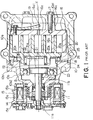
- a housing 10 of the scroll type compressor is provided with a rear housing 10a in the shape of a large-diameter bottomed cylinder and a front housing 10b formed of a large-diameter cylindrical portion 10b1 and a small-diameter cylindrical portion 10b2 and fixed to an open end of the rear housing 10a. Further, the rear housing 10a and the front housing 10b are arranged concentric with each other.
- a shaft 11 extends into the housing 10 along the central axis X of the latter through the small-diameter cylindrical portion 10b2 of the front housing 10b.
- the shaft 11 is provided with a small-diameter portion 11a surrounded by the small-diameter cylindrical portion 10b2 of the front housing 10b and a large-diameter portion 11b surrounded by the large-diameter cylindrical portion 10b1.
- a driving pin 12 extending parallel to, and eccentric with, the axis X.
- the shaft 11 is rotatably supported by the large-diameter cylindrical portion 10b1 of the front housing 10b through a ball bearing 13 while the small-diameter portion 11a is rotatably supported by the small-diameter cylindrical portion 10b2 of the front housing 10b through a ball bearing 14.
- an electromagnetic clutch 15 rotatably fits about the small-diameter cylindrical portion 10b2 of the front housing 10b and is provided with a pulley 15a connected to an external driving source (not shown) by means of a V-belt (not shown), an exciting coil 15b fixed to the small-diameter cylindrical portion 10b2 and a rotation transmitting plate 15c fixed to one end of the small-diameter portion 11a of the shaft 11.
- the shaft 11 is rotated by the external driving source (not shown) through the electromagnetic clutch 15.
- the fixed scroll 16 is provided with a disk-shaped end plate 16a which fits in the rear housing 10a arranged coaxially with the axis X, a spiral body 16b formed on one of the surfaces of the end plate 16a and legs 16c formed on the other surface of the end plate 16a. At the center of the end plate 16a there is formed a discharge hole 16a1.
- the fixed scroll 16 is fixed to the rear housing 10a by means of bolts 17 while the legs 16c are held in contact with the bottom 10a1 of the rear housing 10a.
- the space within the rear housing 10a is divided into an intake chamber 18 and a discharge chamber 19 by means of the end plate 16a of the fixed scroll 16.
- a movable scroll 20 as a revolving member lying adjacent to the fixed scroll 16.
- the movable scroll 20 is provided with a disk-shaped end plate 20a, a spiral body 20b formed on one of the surfaces of the end plate 20a and an annular boss 20c formed on the other surface of the end plate 20a.
- the central axis of the end plate 20a is eccentric with the axis X.
- the spiral body 20b of the movable scroll 20 engages with the spiral body 16b of the fixed scroll 16.
- a thick disk-shaped bush 21 disposed concentric with the end plate 20a. Further, the bush 21 is provided with an eccentric through hole 21a extending parallel to the axis X and a balance weight 23 extending in the radial direction is fixed to the bush 21.
- the through hole 21a houses the driving pin 12 fixed to the large-diameter portion 11b of the shaft 11 so as to allow the pin 12 to slide therein.
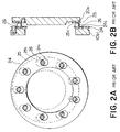
- a fixed race 24 is fixed to one end of the large-diameter cylindrical portion 10b1 of the front housing 10b and a movable race 25 is fixed to the end plate 20a of the movable scroll 20. Further, a plurality of balls 26 are interposed between the fixed race 24 and the movable race 25 in spaced apart relationships with one another in the circumferential direction and a ball coupling for preventing the rotation of the movable scroll 20, that is, a rotation inhibiting mechanism is constructed by these races 24 and 25 and the plurality of balls 26.
- Each of the fixed race 24 and the movable race 25 is formed by a press using a ferrous material and is in the shape of an annular ring.
- the fixed race 24 is provided on one of the surfaces thereof with a plurality of annularly extending ball rolling grooves 24c which are spaced apart from one another in the circumferential direction and likewise, the movable race 25 is provided on one of the surfaces thereof with a plurality of annularly extending ball rolling grooves 25c which are spaced apart from one another in the circumferential direction.
- the balls 26 are made of a bearing steel material and are interposed between the fixed race 24 and the movable race 25 in a state in which they are held sandwiched by the rolling grooves 24c of the fixed race 24 and the opposing ball rolling grooves 25c of the movable race 25.
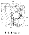
- the inner surface of the ball rolling groove 24c includes an inner peripheral portion 24c1 having a curved surface of a radius of curvature R1, an outer peripheral portion 24c2 having a curved surface of a radius of curvature of R2 and a bottom portion 24c3 connecting the portions 24c1 and 24c2 while the inner surface of the ball rolling groove 25c includes an inner peripheral portion 25c1 having a curved surface of a radius of curvature of R1, an outer peripheral portion 25c2 having a curved surface of a radius of curvature of R2 and a bottom portion 25c3 connecting the portions 25c1 and 25c2.
- the radius of curvature R1 and the radius of curvature R2 may be the same or somewhat different from each other.
- the radii of curvature R1 and R2 bear close resemblance to the radius of each of the balls 26 and are set to a value slightly larger than the value of the radius of the ball 26.
- the bottom portions 24c3 and 25c3 are each in the form of a flat surface so as to become tangential to the inner peripheral portions 24c1 and 25c1 and the outer peripheral portions 24c2 and 25c2, respectively.
- the bottom portions 24c3 and 25c3 form themselves geometrical curved surfaces of large radii of curvature gently connecting the inner peripheral portions 24c1 and 25c1 to the outer peripheral portions 24c2 and 25c2, respectively.
- the central diameter of each of the curved bottom portions 24c3 and 25c3 is set to a value substantially identical with the radius of revolutionary motion of the movable scroll 20.
- the size of the width of each of the bottom portions 24c3 and 25c3 is set to one-third of the width of the effective ball rolling locus and it is desirable to set this size to a value which is determined in anticipation of an error of the shape of each of the scrolls of the scroll type compressor, an error of the attachment position of each of the races and an error of the position of each of the ball rolling grooves.
- the fixed race 24 and the movable race 25 there are provided flat portions 24d and 25d, respectively. These flat portions 24d and 25d are larger in width than the bottom portions 24c3 and 25c3. Accordingly, the fixed race 24 and the movable race 25 are brought into contact with, and supported by, the large-diameter cylindrical portion 10b1 of the front housing 10b and the end plate 20a of the movable scroll 20 as race support members, over a width larger than the width of each of the bottom portions 24c3 and 25c3.
- a fluid flowed into the intake chamber 18 from an external fluid circuit through the intake port (not shown) formed in the housing 10 is taken into the compression chamber from the outer peripheral ends of both of the spiral bodies 16b and 20b, compressed within the compression chamber and flows out into the discharge port 19 through the discharge hole 16a1 formed in the fixed scroll 16.
- the pressurized fluid flowed into the discharge chamber 19 then flows outside the external fluid circuit through the discharge port (not shown) formed in the rear housing 10a.
- reaction force applied on the movable scroll 20 in the direction of the axis X and the movable scroll rotation inhibiting force in the radial direction at the time when the fluid is compressed are transmitted to the front housing 10b through the movable race 25, each of the balls 26 and the fixed race 24.
- each of the balls 26 rolls within the ball rolling grooves 24c and 25c as it draws a circular orbit having a diameter substantially the same as the radius of revolution of the movable scroll 20.
- the diameter of the bottom portion 24c3 (25c3) of the ball rolling groove 24c (25c) is set to a value substantially the same as the value of the radius of revolution of the movable scroll 20
- each of the balls 26 can roll smoothly within the ball rolling grooves 24c and 25c as it draws a circular orbit of a diameter substantially equal to the radius of revolution of the movable scroll 20 in a state in which it is pressed against the bottom portions 24c3 and 25c3 of the ball rolling grooves 24c and 25c, respectively.
- the movable scroll 20 revolves while it keeps a predetermined angular relationship with the front housing 10b, and in the end, with the fixed scroll 16.
- each of the balls 26 rolls generally along the bottom portions 24c3 and 25c3 of the rolling grooves 24c and 25c, respectively. Further, the lines of action of thrust forces F0 acting on the fixed and movable races 24 and 25, respectively, from the ball 26 generally coincide with each other along the axial direction.
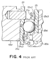
- FIG. 4 A ball coupling as a rotation inhibiting mechanism according to a second prior art technology will be described with reference to Fig. 4 wherein like parts are designated by like reference numerals with respect to the ball coupling shown in Figs. 2A and 2B and Fig. 3 without repeating the description thereof.
- the radius of curvature R3 of the bottom portion 24c3 (25c3) of the ball rolling groove 24c (25c) of the fixed race 24 (the movable race 25) is set to a value far larger than any of the radius of curvature R1 of the inner peripheral portion 24c1 (25c1) of the fixed race 24 (the movable race 25) and the radius of curvature R2 of the outer peripheral portion 24c2 (25c2) of the fixed race 24 (the movable race 25).
- the bottom portion 24c3 (25c3) is so formed as to become tangential to the inner peripheral portion 24c1 (25c1) and the outer peripheral portion 24c2 (25c2).
- the inner surfaces of the ball rolling grooves 24c and 25c are continuously curved so that it is possible to prevent the surface pressure from rising up locally.
- the radius of curvature R1 and the radius of curvature R2 may be identical with, or somewhat different from, each other.
- the bottom portion 24c3 (25c3) of the ball rolling groove 24c (25c) is not always required to be flat. That is, where the inner peripheral portion 24c1 (25c1) and the outer peripheral portion 24c2 (25c2) are made to form curved surfaces whose radii of curvature are R1 and R2, respectively, the bottom portion 24c3 (25c3) may be made to form a geometrical curved surface whose radius of curvature is larger than any of the radii of curvature of R1 and R2.
- FIG. 5 A prior art ball coupling as a rotation inhibiting mechanism according to a third prior art technology will be described with reference to Fig. 5 wherein parts similar to those of the ball coupling shown in Figs. 3 and 4 are designated by the same reference numerals without repeating the description thereof.
- each of the ball rolling grooves 24c (25c) of the fixed race 24 is curved in the form of an annular ellipse having its major axis in the radial direction.
- the inner surface of each of the ball rolling grooves 24c (25c) of the fixed race 24 is formed by one half portion, or a part, of an ellipse having two foci obtained by dividing the ellipse by its major axis.
- the inner surface of the ball rolling groove 240 (25c) becomes continuously curved so that it is possible to prevent the surface pressure from rising locally.
- an object of the present invention is to provide a rotation inhibiting mechanism for a movable scroll of a scroll type fluid machine in which the contact surface pressure between each of movable and fixed races is considerably small.
- Another object of the invention is to provide a rotation inhibiting mechanism for a movable scroll of a scroll type fluid machine suitable for a large-scale production.
- a rotation inhibiting mechanism for a movable scroll of a scroll type fluid machine comprising a fixed scroll having a fixed race provided with a plurality of annular ball rolling grooves extending along a revolutionary locus of the movable scroll, the movable scroll revolving with respect to the fixed scroll and having a movable race fixed to the movable scroll and provided with a plurality of annular ball rolling grooves extending along the revolutionary locus of the movable scroll, the fixed race opposing to the movable race and provided with a plurality of balls sandwiched between the ball rolling grooves of the movable race and those of the fixed race, wherein when the radius of revolution obtained by the movable race, the plurality of balls and the fixed race is S1 and the radius of revolution determined by the walls of the fixed and movable scrolls is S2, the relationship of S1 ⁇ S2 is established.
- a scroll type compressor provided with a ball coupling as a rotation inhibiting mechanism for a movable scroll of the compressor according to one embodiment of the present invention will be described.
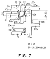
- the basic structure of the scroll type compressor according to one embodiment of the invention is the same as that of the prior art scroll type compressor. Therefore, the essential point of this embodiment will be described by referring to Fig. 7 and Figs. 8A through 8D.
- the rotation inhibiting mechanism for the movable scroll does not allow the movable scroll to rotate although it allows the movable scroll to revolve and it is arranged between the movable scroll and a front housing.
- a spiral body 20b of the movable scroll 20 engages with a spiral body 16b of a fixed scroll.
- An end plate 20a of the movable scroll 20 and a thick disk-shaped bush 21 are arranged concentric with each other and the bush 21 rotatably fits into a boss 20c of the movable scroll 20 through a needle bearing 22.
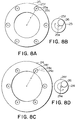
- a movable race 25 shown in Fig. 8A To the end plate 20a of the movable scroll 20 on the side of the front housing 10b there is fixed a movable race 25 shown in Fig. 8A and to the front housing 10b on the side of the movable scroll 20 there is fixed a fixed race 24 shown in Fig. 8C. Further, between six ball rolling grooves 25c of the movable race 25 and six ball rolling grooves 24c of the fixed race 24 there are interposed balls 26, respectively.
- An O-ring 27 is disposed between the front housing 10b and a rear housing.
- Fig. 8A on the circumference of the ring-shaped movable race 25 having a radius r, there are provided the six annular ball rolling grooves 25c at equal intervals. At the center of each of the ball rolling grooves 25c there is formed a projection 25e about which the ball rolls.
- Fig. 8C on the circumference of the ring-shaped fixed race 24 there are provided the six circular ball rolling grooves 24c at equal intervals. At the center of each of the ball rolling grooves 24c there is formed a projection 24e about which the ball rolls.
- the rotation inhibiting mechanism for the movable scroll comprises the movable race 25, the six balls 26 and the fixed race 24.
- the radius of revolution of the movable scroll 20 obtained by the rotation inhibiting mechanism is S1
- the radius of revolution (the radius of turning of the movable scroll) determined by the scroll walls of the movable and fixed scrolls 20 and 16 is S2
- the diameter of the circumferential track of each of the balls 26 in each of the ball rolling grooves 24c of the fixed race 24 is A
- the diameter of the circumferential track of each of the balls 26 in each of the ball rolling grooves 25c of the movable race 25 is B
- the difference between S1 and S2 is desired to be within the range of 0.3 mm.
- each of the ball rolling grooves 25c of the movable race 25 and that of each of the ball rolling grooves 24c of the fixed race 24 is curved in the shape of a circular arc or in a shape closely resembling a circular arc, the rotation inhibiting mechanism can be manufactured with ease.
- the amount of running of each of the balls on the outer edges 24f and 25f of the ball rolling grooves 24c and 25a due to the difference between S1 and S2 is below the minimum resolution of a casing shim used for adjusting the gap between the movable scroll and the fixed scroll of the compressor in the axial direction, the productivity of the compressor does not lower.
- the variation of the contact angle of each of the balls 26 with respect to the fixed and movable races 24 and 25 when the ball runs on the above-mentioned outer edges of the ball rolling grooves 24c and 25c is small so that no so strong component force as to interfere with the favorable contact between the scroll wall of the movable scroll 25 and the scroll wall of the fixed scroll 24 at the time of compressing operation generates.
Landscapes
- Engineering & Computer Science (AREA)
- Mechanical Engineering (AREA)
- General Engineering & Computer Science (AREA)
- Rotary Pumps (AREA)
Applications Claiming Priority (2)
| Application Number | Priority Date | Filing Date | Title |
|---|---|---|---|
| JP1387498 | 1998-01-27 | ||
| JP10013874A JP3115553B2 (ja) | 1998-01-27 | 1998-01-27 | スクロール型流体機械における可動スクロールの自転阻止機構 |
Publications (3)
| Publication Number | Publication Date |
|---|---|
| EP0933501A2 true EP0933501A2 (de) | 1999-08-04 |
| EP0933501A3 EP0933501A3 (de) | 1999-08-18 |
| EP0933501B1 EP0933501B1 (de) | 2003-05-07 |
Family
ID=11845384
Family Applications (1)
| Application Number | Title | Priority Date | Filing Date |
|---|---|---|---|
| EP99101467A Expired - Lifetime EP0933501B1 (de) | 1998-01-27 | 1999-01-27 | Einrichtung zur Rotationshinderung für den umlaufenden Spiralkörper einer Spiralfluidmaschine |
Country Status (5)
| Country | Link |
|---|---|
| US (1) | US6139293A (de) |
| EP (1) | EP0933501B1 (de) |
| JP (1) | JP3115553B2 (de) |
| AU (1) | AU1216999A (de) |
| DE (1) | DE69907529T2 (de) |
Families Citing this family (4)
| Publication number | Priority date | Publication date | Assignee | Title |
|---|---|---|---|---|
| JP4398539B2 (ja) * | 1999-06-01 | 2010-01-13 | サンデン株式会社 | スクロール型圧縮機 |
| JP2001132664A (ja) | 1999-11-04 | 2001-05-18 | Sanden Corp | スクロール型圧縮機 |
| US6315460B1 (en) * | 1999-12-29 | 2001-11-13 | Visteon Global Technologies, Inc. | Orbital motion bearing |
| US9797401B2 (en) * | 2013-12-09 | 2017-10-24 | Mitsubishi Electric Corporation | Scroll compressor |
Family Cites Families (28)
| Publication number | Priority date | Publication date | Assignee | Title |
|---|---|---|---|---|
| GB1257658A (de) * | 1969-04-22 | 1971-12-22 | ||
| US4259043A (en) * | 1977-06-17 | 1981-03-31 | Arthur D. Little, Inc. | Thrust bearing/coupling component for orbiting scroll-type machinery and scroll-type machinery incorporating the same |
| JPS56141087A (en) * | 1980-04-05 | 1981-11-04 | Sanden Corp | Scroll type compressor |
| JPS6017959B2 (ja) * | 1980-10-09 | 1985-05-08 | サンデン株式会社 | スクロ−ル型圧縮機 |
| JPS6022199B2 (ja) * | 1981-03-09 | 1985-05-31 | サンデン株式会社 | スクロ−ル型圧縮機 |
| JPS57148087A (en) * | 1981-03-09 | 1982-09-13 | Sanden Corp | Scroll type compressor |
| JPS57157085A (en) * | 1981-03-23 | 1982-09-28 | Sanden Corp | Apparatus having element moved along circular orbiting path |
| JPS57195801A (en) * | 1981-05-27 | 1982-12-01 | Sanden Corp | Fluidic device of volute type |
| JPS6037320B2 (ja) * | 1981-10-12 | 1985-08-26 | サンデン株式会社 | スクロ−ル型圧縮機 |
| US4472120A (en) * | 1982-07-15 | 1984-09-18 | Arthur D. Little, Inc. | Scroll type fluid displacement apparatus |
| JPS5928082A (ja) * | 1982-08-07 | 1984-02-14 | Sanden Corp | 旋回ピストン式流体機械 |
| JPS5952193U (ja) * | 1982-09-30 | 1984-04-05 | サンデン株式会社 | スクロ−ル型圧縮機 |
| JPS59142483U (ja) * | 1983-03-15 | 1984-09-22 | サンデン株式会社 | スクロ−ル型圧縮機の回転阻止機構 |
| JPS60104788A (ja) * | 1983-11-14 | 1985-06-10 | Sanden Corp | スクロ−ル型圧縮機 |
| JPS60111080A (ja) * | 1983-11-19 | 1985-06-17 | Sanden Corp | スクロ−ル型圧縮機 |
| JPH0781556B2 (ja) * | 1987-01-21 | 1995-08-30 | 岩田塗装機工業株式会社 | 空冷オイルレススクロ−ル圧縮機のスラスト軸受機構 |
| JPS63266214A (ja) * | 1987-04-22 | 1988-11-02 | Daikin Ind Ltd | ボ−ル継手機構 |
| JPS63280882A (ja) * | 1987-05-11 | 1988-11-17 | Matsushita Electric Ind Co Ltd | スクロ−ル型圧縮機 |
| JPH01167481A (ja) * | 1987-12-21 | 1989-07-03 | Toyota Autom Loom Works Ltd | スクロール型圧縮機 |
| JPH03105088A (ja) * | 1989-09-18 | 1991-05-01 | Sanden Corp | スクロール型圧縮機 |
| US5221198A (en) * | 1990-07-18 | 1993-06-22 | Kabushiki Kaisha Toyoda Jidoshokki Seisakusho | Scroll type compressor with intake port aligned with counterweight |
| JP2997103B2 (ja) * | 1991-07-26 | 2000-01-11 | エヌティエヌ株式会社 | スラスト玉軸受 |
| JP3012063B2 (ja) * | 1991-07-26 | 2000-02-21 | エヌティエヌ株式会社 | スラスト玉軸受 |
| JPH05126140A (ja) * | 1991-11-06 | 1993-05-21 | Ntn Corp | 旋回部材のスラスト支持装置 |
| JPH0649783U (ja) * | 1992-12-07 | 1994-07-08 | サンデン株式会社 | スクロール流体機械 |
| JP2873359B2 (ja) * | 1993-06-30 | 1999-03-24 | 株式会社アキタファインブランキング | スクロール流体機械におけるリテーナリング並びにその製造方法 |
| JP3053551B2 (ja) * | 1995-08-03 | 2000-06-19 | サンデン株式会社 | ボールカップリング |
| JP3136267B2 (ja) * | 1996-05-21 | 2001-02-19 | サンデン株式会社 | スクロール型圧縮機の回転阻止機構 |
-
1998
- 1998-01-27 JP JP10013874A patent/JP3115553B2/ja not_active Expired - Lifetime
-
1999
- 1999-01-21 AU AU12169/99A patent/AU1216999A/en not_active Abandoned
- 1999-01-26 US US09/236,551 patent/US6139293A/en not_active Expired - Lifetime
- 1999-01-27 EP EP99101467A patent/EP0933501B1/de not_active Expired - Lifetime
- 1999-01-27 DE DE69907529T patent/DE69907529T2/de not_active Expired - Lifetime
Also Published As
| Publication number | Publication date |
|---|---|
| JPH11210647A (ja) | 1999-08-03 |
| AU1216999A (en) | 1999-08-19 |
| EP0933501A3 (de) | 1999-08-18 |
| US6139293A (en) | 2000-10-31 |
| DE69907529T2 (de) | 2004-03-18 |
| DE69907529D1 (de) | 2003-06-12 |
| JP3115553B2 (ja) | 2000-12-11 |
| EP0933501B1 (de) | 2003-05-07 |
Similar Documents
| Publication | Publication Date | Title |
|---|---|---|
| EP0061698B1 (de) | Vorrichtung mit kreisendem Kolben zum Fördern von Fluiden, mit einer Einrichtung zum Verhindern der Rotation | |
| JPH0237192A (ja) | スクロール型流体装置 | |
| JP3136267B2 (ja) | スクロール型圧縮機の回転阻止機構 | |
| JPH04358784A (ja) | スクロール圧縮機 | |
| JP3053551B2 (ja) | ボールカップリング | |
| JPH02308991A (ja) | スクロール型圧縮機 | |
| JP3018850B2 (ja) | スクロール型圧縮機 | |
| EP0933501B1 (de) | Einrichtung zur Rotationshinderung für den umlaufenden Spiralkörper einer Spiralfluidmaschine | |
| JP2997103B2 (ja) | スラスト玉軸受 | |
| JPH0630486U (ja) | スクロール型圧縮機 | |
| US6206665B1 (en) | Rotation inhibiting mechanism for movable scroll of scroll type fluid machine | |
| JPH0649783U (ja) | スクロール流体機械 | |
| JP2734408B2 (ja) | スクロール圧縮機 | |
| JPH09303274A (ja) | スクロール型圧縮機 | |
| US5597297A (en) | Scroll type compressor | |
| JP2000046048A (ja) | スクロールスラスト軸受 | |
| JPH08219053A (ja) | スクロール型圧縮機 | |
| JP3227290B2 (ja) | スクロール型圧縮機 | |
| JP2000120563A (ja) | スクロール型圧縮機 | |
| JP2594717B2 (ja) | スクロール式流体機械 | |
| JP2002250338A (ja) | スラスト軸受装置 | |
| US6315460B1 (en) | Orbital motion bearing | |
| JPH094639A5 (de) | ||
| JPH10220367A (ja) | スクロール型圧縮機 | |
| JPH09324816A (ja) | スラスト玉軸受 |
Legal Events
| Date | Code | Title | Description |
|---|---|---|---|
| PUAI | Public reference made under article 153(3) epc to a published international application that has entered the european phase |
Free format text: ORIGINAL CODE: 0009012 |
|
| PUAL | Search report despatched |
Free format text: ORIGINAL CODE: 0009013 |
|
| AK | Designated contracting states |
Kind code of ref document: A2 Designated state(s): DE FR |
|
| AX | Request for extension of the european patent |
Free format text: AL;LT;LV;MK;RO;SI |
|
| AK | Designated contracting states |
Kind code of ref document: A3 Designated state(s): AT BE CH CY DE DK ES FI FR GB GR IE IT LI LU MC NL PT SE |
|
| AX | Request for extension of the european patent |
Free format text: AL;LT;LV;MK;RO;SI |
|
| 17P | Request for examination filed |
Effective date: 20000215 |
|
| AKX | Designation fees paid |
Free format text: DE FR |
|
| GRAH | Despatch of communication of intention to grant a patent |
Free format text: ORIGINAL CODE: EPIDOS IGRA |
|
| GRAH | Despatch of communication of intention to grant a patent |
Free format text: ORIGINAL CODE: EPIDOS IGRA |
|
| GRAA | (expected) grant |
Free format text: ORIGINAL CODE: 0009210 |
|
| AK | Designated contracting states |
Designated state(s): DE FR |
|
| REF | Corresponds to: |
Ref document number: 69907529 Country of ref document: DE Date of ref document: 20030612 Kind code of ref document: P |
|
| ET | Fr: translation filed | ||
| PLBE | No opposition filed within time limit |
Free format text: ORIGINAL CODE: 0009261 |
|
| STAA | Information on the status of an ep patent application or granted ep patent |
Free format text: STATUS: NO OPPOSITION FILED WITHIN TIME LIMIT |
|
| 26N | No opposition filed |
Effective date: 20040210 |
|
| REG | Reference to a national code |
Ref country code: FR Ref legal event code: PLFP Year of fee payment: 17 |
|
| PGFP | Annual fee paid to national office [announced via postgrant information from national office to epo] |
Ref country code: DE Payment date: 20150121 Year of fee payment: 17 |
|
| PGFP | Annual fee paid to national office [announced via postgrant information from national office to epo] |
Ref country code: FR Payment date: 20150122 Year of fee payment: 17 |
|
| REG | Reference to a national code |
Ref country code: DE Ref legal event code: R119 Ref document number: 69907529 Country of ref document: DE |
|
| REG | Reference to a national code |
Ref country code: FR Ref legal event code: ST Effective date: 20160930 |
|
| PG25 | Lapsed in a contracting state [announced via postgrant information from national office to epo] |
Ref country code: DE Free format text: LAPSE BECAUSE OF NON-PAYMENT OF DUE FEES Effective date: 20160802 |
|
| PG25 | Lapsed in a contracting state [announced via postgrant information from national office to epo] |
Ref country code: FR Free format text: LAPSE BECAUSE OF NON-PAYMENT OF DUE FEES Effective date: 20160201 |