EP0936600B1 - Support d'enregistrement magnétique, procédé pour sa fabrication et procédé pour la formation d'un film par plasma CVD - Google Patents
Support d'enregistrement magnétique, procédé pour sa fabrication et procédé pour la formation d'un film par plasma CVD Download PDFInfo
- Publication number
- EP0936600B1 EP0936600B1 EP98118269A EP98118269A EP0936600B1 EP 0936600 B1 EP0936600 B1 EP 0936600B1 EP 98118269 A EP98118269 A EP 98118269A EP 98118269 A EP98118269 A EP 98118269A EP 0936600 B1 EP0936600 B1 EP 0936600B1
- Authority
- EP
- European Patent Office
- Prior art keywords
- film
- magnetic recording
- coating layer
- back coating
- recording medium
- Prior art date
- Legal status (The legal status is an assumption and is not a legal conclusion. Google has not performed a legal analysis and makes no representation as to the accuracy of the status listed.)
- Expired - Lifetime
Links
Images

Classifications
-
- G—PHYSICS
- G11—INFORMATION STORAGE
- G11B—INFORMATION STORAGE BASED ON RELATIVE MOVEMENT BETWEEN RECORD CARRIER AND TRANSDUCER
- G11B5/00—Recording by magnetisation or demagnetisation of a record carrier; Reproducing by magnetic means; Record carriers therefor
- G11B5/84—Processes or apparatus specially adapted for manufacturing record carriers
- G11B5/8404—Processes or apparatus specially adapted for manufacturing record carriers manufacturing base layers
-
- G—PHYSICS
- G11—INFORMATION STORAGE
- G11B—INFORMATION STORAGE BASED ON RELATIVE MOVEMENT BETWEEN RECORD CARRIER AND TRANSDUCER
- G11B5/00—Recording by magnetisation or demagnetisation of a record carrier; Reproducing by magnetic means; Record carriers therefor
- G11B5/62—Record carriers characterised by the selection of the material
- G11B5/73—Base layers, i.e. all non-magnetic layers lying under a lowermost magnetic recording layer, e.g. including any non-magnetic layer in between a first magnetic recording layer and either an underlying substrate or a soft magnetic underlayer
- G11B5/735—Base layers, i.e. all non-magnetic layers lying under a lowermost magnetic recording layer, e.g. including any non-magnetic layer in between a first magnetic recording layer and either an underlying substrate or a soft magnetic underlayer characterised by the back layer
Definitions
- the present invention relates to a method for forming a film by a plasma CVD (chemical vapor deposition).
- the present invention relates to a magnetic recording medium which is used in an audio or video equipment, a computer, and the like, and has a back coating layer on a surface of a nonmagnetic substrate reverse to a magnetic recording layer.
- a magnetic recording equipment is required to have a large capacity, achieve high speed reading and writing, high picture and sound quality, and have a small size and a light weight. To satisfy such requirements, it is inevitable for a magnetic recording medium to achieve a high density recording.
- a ferromagnetic metal thin film magnetic recording medium instead of a conventional powder coating type magnetic recording medium having a magnetic layer which comprises a binder and magnetic powder dispersed in said binder, a ferromagnetic metal thin film magnetic recording medium has been actively developed and practically used, since it has a larger residual magnetic flux density (Br) and coercive force (Hc) and a thinner magnetic layer, and is more suitable for ultra-smoothing of a magnetic layer surface than the powder coating type one.
- the surface roughness of the back coating layer in particular that of the ferromagnetic metal thin film magnetic recording medium should be as small as possible to decrease a so-called back transfer, that is, shape transfer of unevenness of the back coating layer to the magnetic layer surface in a winding up step or a heat treating step, and to prevent deterioration of electromagnetic conversion characteristics.
- worn debris from the back coating layer is transferred to the magnetic layer surface during tape winding and may clog a magnetic head, increase the number of drop-outs or decrease output signal level.
- the magnetic recording medium When the magnetic recording medium is stored for a long time, it suffers from blocking, namely adhesion of the magnetic layer and the back coating layer each other.
- the magnetic layer of the ferromagnetic metal thin film magnetic recording medium has low hardness and is easily abraded, it is proposed to form, on the magnetic layer, a diamond-like carbon film and a fluorine-containing lubricant layer having a lubricity and water-repellency, successively to improve running stability and durability.
- the lubricant component migrates to the back coating layer so that an amount of the lubricant on the diamond-like carbon film is reduced, and then a still-frame life is decreased.
- JP-A-353616/1992 discloses a magnetic recording medium comprising a back coating layer on a surface of a nonmagnetic substrate reverse to a magnetic layer and a fluorine-containing hard carbon film on the back coating layer to improve wear resistance of the back coating layer and also to prevent the blocking and migration of a lubricant component from a lubricant layer to the back coating layer.
- EP-A-0264699 representing the closed prior art for which the invention proceeds, discloses a method for depositing protective coatings on magnetic tapes provided with metal film wherein the top of a partition wall terminates very closely to a temperature-adjusted drum so that there is only a very thin gap between the partition wall and the drum.
- the film formed by such method includes two distinct layers, the first one of which is formed in a first vacuum system at the one side of the partition wall and the second one of which is formed in a second vacuum system at the other side of the partition wall. As a result, the film cannot have a continuously changed composition.
- An object of the present invention is to provide an improved method for forming a film by a plasma CVD method.
- a method for forming a film having continuously changed composition by a plasma CVD method comprising generating glow discharge plasma in a substrate placed in a vacuum chamber using a discharge tube facing said substrate and having at least one partition plate, characterized in that a distance between a top end of said partition plate and said substrate surface is larger than a distance between a top end of said discharge tube and said substrate surface.
- the distance between the top end of said partition plate and said substrate surface is at least 2 times larger than the distance between the top end of said discharge tube and said substrate surface.
- a magnetic recording medium produced by the method according to the present invention can achieve good wear resistance and low energy surface properties (water and oil repellency) while maintaining the good adhesion between the carbonaceous film and the back coating layer. Therefore, the present invention can provide a magnetic recording medium which is excellent in the running stability, durability and weatherability without deteriorating the electromagnetic conversion characteristics.
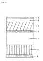
- Fig. 1 shows an enlarged cross section of an example of the ferromagnetic metal thin film magnetic tape according to the present invention, which comprises a nonmagnetic substrate 1, on one surface, a ferromagnetic metal thin film 3, a diamond-like carbon film 4, a lubricant layer 7, and on the other surface, a back coating layer 5 and a carbonaceous film 6.
- the nonmagnetic substrate may be made of any one of conventionally used materials, preferably, a polymer film of, for example, polyethylene terephthalate, polyethylene naphthalate, polyamide, polyimide, and so on.
- a thickness of the nonmagnetic substrate is not critical and can be the same as that of the conventional nonmagnetic substrate.
- a minute protrusion layer 2 is formed on the surface of the nonmagnetic substrate on which the magnetic layer is formed.
- the minute protrusion layer has a maximum height roughness (R max ) of 10 nm to 20 nm.
- the ferromagnetic metal thin film 3 may be formed by a conventional method.
- a ferromagnetic metal or an alloy of ferromagnetic metals such as Co, Co-Ni, etc. is heated and evaporated by, for example, an electron beam under reduced pressure in a vacuum chamber and deposited on the substrate by an oblique vapor deposition method in which an incident angle of the metal vapor is continuously changed while introducing a small amount of an oxygen gas in the vacuum chamber.
- a thickness of the ferromagnetic metal film 3 is preferably from 150 to 200 nm, while it is possible to decrease or increase the thickness depending on a kind of the magnetic recording medium.
- the diamond-like carbon film 4 can be formed by any one of conventional methods such as a plasma CVD method, an ion beam vapor deposition method, an ion beam sputtering method, a laser vapor deposition method, and so on.
- a thickness of the diamond-like film 4 is arbitrary and preferably from 8 nm to 12 nm to maintain a reproducing signal level in a short wavelength range.
- the back coating layer 5 is formed by, for example, coating a back coating paint comprising a filler (e.g. carbon black, calcium carbonate, etc.), a binder resin (e.g. polyester resin, nitrocellulose resin, etc.) and other necessary additive or additives and drying it.
- a filler e.g. carbon black, calcium carbonate, etc.
- a binder resin e.g. polyester resin, nitrocellulose resin, etc.
- a thickness of the back coating layer is not critical and preferably up to about 500 nm.
- the carbonaceous film 6 contains the fluorine atoms and at least one kind of atoms selected from the group consisting of silicon atoms and nitrogen atoms. In this film 6, a concentration of the fluorine atoms decreases in the depth direction from the surface of the film 6, while a concentration of the silicon and/or nitrogen atoms increases in the depth direction from the surface of the film 6.
- the concentration of the fluorine atoms may change continuously or stepwise.
- a thickness of the carbonaceous film 6 is usually from 3 nm to 50 nm, preferably from 5 nm to 30 nm.
- the lubricant layer 7 preferably comprises a fluorine-containing lubricant and is formed by a wet coating method or an organic vapor deposition method. Its thickness is usually up to about 3 nm.
- the lubricant preferably has at least one polar group, such as -COOH, -OH, -SH, -NH 2 , >NH, -NCO, -CONH 2 , -CONHR, -CONR 2 , -COOR, >PR, >PRO, -PRS, -OPO(OH) 2 , -OPO(OR) 2 , and -SO 3 M in which R is a C 1 -C 22 hydrocarbon group, and M is a hydrogen atom, an alkali metal or an alkaline earth metal.
- polar group such as -COOH, -OH, -SH, -NH 2 , >NH, -NCO, -CONH 2 , -CONHR, -CONR 2 , -COOR, >PR, >PRO, -PRS, -OPO(OH) 2 , -OPO(OR) 2 , and -SO 3 M in which R is a C 1 -C 22 hydrocarbon group,
- Fig. 2 schematically shows an embodiment of an apparatus for forming the carbonaceous film 6 constituting the ferromagnetic metal thin film magnetic tape according to the present invention by the plasma CVD method.
- the apparatus comprises a vacuum chamber 8 which is evacuated by a vacuum pump 9 to a pressure of, for example, 10 -4 torr to 10 -5 torr.
- a sheet 10 for a magnetic recording tape which comprises the nonmagnetic substrate 1, the ferromagnetic metal thin film 3, the back coating layer 5 and the diamond-like carbon film 4 is supplied from an unwinder roll 11, passes around a pass roll 12, a cylindrical cooling can 14 and then a pass roll 13, and is taken up on a winder roll 15.
- the cooling can 14 functions to control a conveying rate of the sheet 10 at a constant rate.
- the discharge tube 28 for forming the carbonaceous film 6 on the back coating layer of the sheet 10.
- the discharge tube 28 has a partition plate 29 and two pipe-form discharge electrodes 30 and 31.
- a distance between the top end of the discharge tube 28 and the sheet 10 is 0.5 mm
- a distance between the top end of the partition plate 29 and the sheet 10 is 5 mm.
- the pipe-form discharge electrodes 30 and 31 are connected to plasma-generating power sources 32 and 33, respectively.
- the power source any of a system for applying a direct current or an alternating current and a system for superposing the direct current and the alternating current can be used.
- the fluorine-containing organic compound gas, the silicon-containing organic compound gas, the nitrogen-containing organic compound gas, the silicon and nitrogen-containing organic compound gas, and an inert gas such as argon can be supplied in the discharging electrode 28 from gas inlets 34 and 35.
- any of conventionally used organic compounds may be used.
- fluorine-containing organic compound fluoromethane, difluoromethane, trifluoromethane, tetrafluoromethane, fluoroethylene, difluoroethylene, trifluoroethylene, tetrafluoroethylene, fluoroethane, difluoroethane, trifluoroethane, tetrafluoroethane, pentafluoroethane, hexafluoroethane, fluoropropylene, difluoropropylene, trifluoropropylene, tetrafluoropropylene, pentafluoropropylene, hexafluoropropylene, fluorobutadiene, difluorobutadiene, trifluorobutadiene, tetrafluorobutadiene, pentafluorobutadiene, hexafluorobutadiene, octafluorocyclobutane, per
- Preferred examples of the silicon-containing organic compound are trimethoxysilane, tetramethylsilane, methoxytrimethylsilane, dimethoxydimethylsilane, diethoxysilane, methyltrimethoxysilane, tetramethoxysilane, allyldimethylsilane,trimethylvinylsilane, ethyltrimethylsilane, ethyltrimethoxysilane, tetramethyldisiloxane, pentamethyldisiloxane, hexamethyldisiloxane, and the like.
- Preferred examples of the nitrogen-containing organic compound are methylamine, ethylamine, propylamine, butylamine, pentylamine, vinylamine, allylamine, dimethylamine, diethylamine, trimethylamine, triethylamine, pyridine, picoline, pyridazine, pyrimidine, pyrazine, acrylamide, acrylonitrile, acetonitrile, aniline, toluidine, phenylenediamine, and the like.
- Preferred examples of the silicon and nitrogen-containing organic compound are aminomethyltrimethylsilane, dimethyldimethylaminosilane, dimethylaminotrimethylsilane, tetramethyldisilazane, hexamethyldisilazane, heptamethyldisilazane, hexamethoxydisilazane, and the like.
- a hydrocarbon which does not contain fluorine, silicon or nitrogen atoms such as methane, ethane, benzene, toluene and so on can be used.
- a ferromagnetic metal thin film 3 of Co-O having a thickness of 180 nm was formed by the continuously incident angle changing vapor deposition method.
- a diamond-like carbon film 4 having a thickness of 10 nm was formed by the plasma CVD method using a mixed gas of methane and argon in a volume ratio of 4:1.
- a back coating layer 5 having a thickness of 500 nm after drying was formed by coating the same solution as used in Example 1 by the wet coating method.
- the formed sheet 10 was set on the supply roll 11 in the vacuum chamber 8 of the apparatus of Fig. 2.
- tetrametyldisiloxane and argon in a volume ratio of 4:1 were introduced in the discharge tube 28 with adjusting a total gas pressure to 27 Pa (0.20 torr.) by controlling the flow rates of the gasses.
- octafluorocyclobutane and argon in a volume ratio of 4:1 were introduced in the discharge tube 28 with adjusting a total gas pressure to 27 Pa (0.20 torr.) by controlling the flow rates of the gasses.
- the sheet 10 was conveyed at a running rate of 15 m/min. around the can 14 while a direct current of 800 V and an alternating current of 800 V having a frequency of 20 kHz were superposed and applied to each of the discharge electrodes 30 and 31 to generate nonequilibrium plasma in the discharge tube 28, whereby a carbonaceous film 6 having a thickness of 10 nm was formed on the surface of the back coating layer 5, in which film 6, a concentration of the fluorine atoms continuously decreased in the depth direction from its surface towards the interface between the back coating layer and the carbonaceous film, while a concentration of the silicon atom increased in the depth direction from its surface.
- the chemical composition of the carbonaceous film 6 on the sheet 10 was analyzed by X-ray photoelectron spectroscopy (XPS) to find that an atomic ratio of the fluorine atoms to the carbon atoms near the surface of the carbonaceous film 6 was 23 %.
- XPS X-ray photoelectron spectroscopy
- a critical surface tension ⁇ c on the surface of the carbonaceous film 6 of the magnetic tape was 18.6 x 10 -5 N/cm.
- Example 2 In the same manner as in Example 1 except that pyridine was used in place of tetramethyldisiloxane, pyridine and argon in a volume ratio of 4:1 were introduced in the discharge tube 28 from the inlet 34, the total gas pressure in the discharge tube 28 was adjusted to 33 Pa (0.25 torr.) and a direct current of 1000 V and an alternating current of 1300 V having a frequency of 20 kHz were superposed and applied to the discharge electrode 30, and a thickness of the carbonaceous film 6 was 21 nm, a 8 mm VTR tape was produced.
- the chemical composition of the carbonaceous film 6 on the sheet 10 was analyzed by X-ray photoelectron spectroscopy (XPS) to find that an atomic ratio of the fluorine atoms to the carbon atoms near the surface of the carbonaceous film 6 was 20 %.
- XPS X-ray photoelectron spectroscopy
- a critical surface tension ⁇ c on the surface of the carbonaceous film 6 of the magnetic tape was 18.9 x 10 -5 N/cm.
- Each of four wettability standard solutions having surface tensions of 38 x 10 -5 , 45 x 10 -5 , 54 x 10 -5 and 72 x 10 -5 N/cm, respectively, was dropped on the surface of the carbonaceous film and a contact angle ⁇ of each of the solutions was measured. Then, cosines of angles ⁇ (cos ⁇ ) were plotted against surface tensions of the wettability standard solutions (Zisman plot). A surface tension corresponding to an intersection between a line obtained by the least square method from the plot and the line at cos ⁇ 1.0 was read and this value was defined as the critical surface tension ⁇ c .
- a coefficient of friction obtained after 30 passes is used.
- a video signal is recorded on a magnetic tape of about 60 minutes long, and reproduced in 200 passes (the running durability test).
- the RF output in the first pass as the standard (0 dB)
- the lowest RF output in the 200 passes is represented in the unit of "dB".
- a magnetic tape which has been stored at 40°C, 90 %RH for about 10 days is reproduced in a still mode at 23°C, 10 %RH under a load of 20 g, and a time at which the RF output decreases by 6 dB is measured. The measurement is terminated after 60 minutes.
- the carbonaceous films produced in the above Examples contained the fluorine atoms and the silicon and/or nitrogen atoms and the concentration of the fluorine atoms decreased in the depth direction from the surface of the carbonaceous film while the concentrations of the silicon and/or nitrogen atoms increased in the depth direction from the surface of the carbonaceous film. Since such carbonaceous film was formed on the back coating layer, the adhesion between the carbonaceous film and the back coating layer was maintained good and further the carbonaceous film could achieve sufficient wear resistance, low energy surface properties (water and oil repellency) and so on. Accordingly, the running stability, decrease of output signal and head clogging were greatly improved, and also anti-blocking and still-frame life were increased.
- the metal thin film 8 mm VTR tapes were produced.
- the present invention can be applied to other metal thin film magnetic recording media, and the particulate magnetic recording media.
- the plasma CVD method which can form the carbonaceous film having a continuously changed composition according to the present invention can be employed in the formation of the plasma polymerization film or a diamond-like carbon film which is used as a protective film on a ferromagnetic metal thin film, the formation of an insulating film for a semiconductor or a liquid crystal, the formation of an amorphous silicon which is used in an photoelectric transfer device, the formation of a superconductive thin film, and so on.
Landscapes
- Engineering & Computer Science (AREA)
- Manufacturing & Machinery (AREA)
- Manufacturing Of Magnetic Record Carriers (AREA)
- Magnetic Record Carriers (AREA)
- Chemical Vapour Deposition (AREA)
Claims (2)
- Procédé de formation d'un film ayant une composition modifiée en permanence par un procédé de dépôt chimique en phase vapeur activé au plasma (plasma CVD) comprenant la génération de plasma de décharge luminescente sur un substrat (10) placé dans une chambre à vide (8) utilisant un tube de décharge (28) placé en face dudit substrat et ayant au moins une plaque de séparation (29), dans lequel ledit substrat est déplacé à côté dudit tube de décharge (28) et une composition de gaz d'une source différente est délivrée de chaque côté de ladite plaque de séparation (29) ;
caractérisé en ce qu'une distance entre une extrémité supérieure de ladite plaque de séparation (29) et ladite surface du substrat est supérieure à une distance entre une extrémité supérieure dudit tube de décharge (28) et ladite surface du substrat. - Procédé selon la revendication 1, dans lequel la distance entre l'extrémité supérieure de ladite plaque de séparation (29) et ladite surface du substrat est au moins deux fois plus grande que la distance entre l'extrémité supérieure dudit tube de décharge (28) et ladite surface du substrat.
Applications Claiming Priority (3)
| Application Number | Priority Date | Filing Date | Title |
|---|---|---|---|
| JP26217793 | 1993-10-20 | ||
| JP26217793A JP3419045B2 (ja) | 1993-10-20 | 1993-10-20 | 磁気記録媒体の製造方法 |
| EP94116379A EP0650158B1 (fr) | 1993-10-20 | 1994-10-18 | Support d'enregistrement magnétique, méthode de fabrication de ce support |
Related Parent Applications (1)
| Application Number | Title | Priority Date | Filing Date |
|---|---|---|---|
| EP94116379A Division EP0650158B1 (fr) | 1993-10-20 | 1994-10-18 | Support d'enregistrement magnétique, méthode de fabrication de ce support |
Publications (3)
| Publication Number | Publication Date |
|---|---|
| EP0936600A2 EP0936600A2 (fr) | 1999-08-18 |
| EP0936600A3 EP0936600A3 (fr) | 1999-09-01 |
| EP0936600B1 true EP0936600B1 (fr) | 2004-08-18 |
Family
ID=17372142
Family Applications (2)
| Application Number | Title | Priority Date | Filing Date |
|---|---|---|---|
| EP98118269A Expired - Lifetime EP0936600B1 (fr) | 1993-10-20 | 1994-10-18 | Support d'enregistrement magnétique, procédé pour sa fabrication et procédé pour la formation d'un film par plasma CVD |
| EP94116379A Expired - Lifetime EP0650158B1 (fr) | 1993-10-20 | 1994-10-18 | Support d'enregistrement magnétique, méthode de fabrication de ce support |
Family Applications After (1)
| Application Number | Title | Priority Date | Filing Date |
|---|---|---|---|
| EP94116379A Expired - Lifetime EP0650158B1 (fr) | 1993-10-20 | 1994-10-18 | Support d'enregistrement magnétique, méthode de fabrication de ce support |
Country Status (4)
| Country | Link |
|---|---|
| US (1) | US5496595A (fr) |
| EP (2) | EP0936600B1 (fr) |
| JP (1) | JP3419045B2 (fr) |
| DE (2) | DE69433956T2 (fr) |
Families Citing this family (12)
| Publication number | Priority date | Publication date | Assignee | Title |
|---|---|---|---|---|
| US5688556A (en) * | 1994-04-01 | 1997-11-18 | Mobil Oil Corporation | Barrier films having vapor coated EVOH surfaces |
| WO1997037053A1 (fr) * | 1996-04-01 | 1997-10-09 | Mobil Oil Corporation | Films formant barriere presentant des surfaces a haute energie revetues en phase vapeur |
| US5989998A (en) * | 1996-08-29 | 1999-11-23 | Matsushita Electric Industrial Co., Ltd. | Method of forming interlayer insulating film |
| US5888594A (en) * | 1996-11-05 | 1999-03-30 | Minnesota Mining And Manufacturing Company | Process for depositing a carbon-rich coating on a moving substrate |
| US5948166A (en) * | 1996-11-05 | 1999-09-07 | 3M Innovative Properties Company | Process and apparatus for depositing a carbon-rich coating on a moving substrate |
| JP2001135630A (ja) * | 1999-11-10 | 2001-05-18 | Matsushita Electronics Industry Corp | 半導体装置の製造方法 |
| JP4826004B2 (ja) * | 2000-09-28 | 2011-11-30 | 凸版印刷株式会社 | 真空成膜装置及び真空成膜方法 |
| US7568445B2 (en) | 2000-11-17 | 2009-08-04 | Lockheed Martin Corporation | System and method for the holographic deposition of material |
| JP2003098305A (ja) * | 2001-09-19 | 2003-04-03 | Sumitomo Metal Mining Co Ltd | 反射防止フィルム |
| JP2006312778A (ja) * | 2005-04-06 | 2006-11-16 | Toyo Seikan Kaisha Ltd | 表面波プラズマによる蒸着膜の形成方法及び装置 |
| KR101632397B1 (ko) * | 2014-10-31 | 2016-06-21 | (주)에스엔텍 | 플라즈마 화학기상 장치 |
| US20230227689A1 (en) * | 2020-05-18 | 2023-07-20 | Jiangsu Favored Nanotechnology Co., LTD | Water-resistant film layer and article thereof |
Family Cites Families (15)
| Publication number | Priority date | Publication date | Assignee | Title |
|---|---|---|---|---|
| JPS56148732A (en) * | 1980-04-17 | 1981-11-18 | Matsushita Electric Ind Co Ltd | Thin metallic film type magnetic recording medium |
| JPS57135442A (en) * | 1981-02-16 | 1982-08-21 | Fuji Photo Film Co Ltd | Magnetic recording medium and its manufacture |
| GB2166668B (en) * | 1984-11-09 | 1988-03-09 | Tdk Corp | Magnetic recording medium |
| US4840844A (en) * | 1986-06-02 | 1989-06-20 | Hitachi, Ltd. | Magnetic recording medium |
| JPS6387988A (ja) * | 1986-10-01 | 1988-04-19 | Nisshin Oil Mills Ltd:The | 消化吸収性の良い油脂 |
| DE3635524A1 (de) * | 1986-10-18 | 1988-04-28 | Leybold Ag | Verfahren zum herstellen von schutzschichten auf magnetischen datentraegern und durch das verfahren hergestellter datentraeger |
| US5283087A (en) * | 1988-02-05 | 1994-02-01 | Semiconductor Energy Laboratory Co., Ltd. | Plasma processing method and apparatus |
| US5275850A (en) * | 1988-04-20 | 1994-01-04 | Hitachi, Ltd. | Process for producing a magnetic disk having a metal containing hard carbon coating by plasma chemical vapor deposition under a negative self bias |
| JPH0394069A (ja) * | 1989-09-05 | 1991-04-18 | Mitsubishi Electric Corp | 薄膜形成装置 |
| JPH0449520A (ja) * | 1990-06-19 | 1992-02-18 | Matsushita Electric Ind Co Ltd | 磁気テープ |
| US5198263A (en) * | 1991-03-15 | 1993-03-30 | The United States Of America As Represented By The United States Department Of Energy | High rate chemical vapor deposition of carbon films using fluorinated gases |
| JPH04353616A (ja) * | 1991-05-30 | 1992-12-08 | Matsushita Electric Ind Co Ltd | 磁気記録媒体 |
| JPH0525648A (ja) * | 1991-07-15 | 1993-02-02 | Matsushita Electric Ind Co Ltd | プラズマcvd成膜方法 |
| US5204138A (en) * | 1991-12-24 | 1993-04-20 | International Business Machines Corporation | Plasma enhanced CVD process for fluorinated silicon nitride films |
| DE69311611T2 (de) * | 1992-03-30 | 1997-10-02 | Matsushita Electric Ind Co Ltd | Verfahren zur Herstellung eines Überzuges durch chemische Abscheidung aus der Dampfphase mittels Plasma |
-
1993
- 1993-10-20 JP JP26217793A patent/JP3419045B2/ja not_active Expired - Fee Related
-
1994
- 1994-10-18 DE DE69433956T patent/DE69433956T2/de not_active Expired - Fee Related
- 1994-10-18 DE DE69419868T patent/DE69419868T2/de not_active Expired - Fee Related
- 1994-10-18 EP EP98118269A patent/EP0936600B1/fr not_active Expired - Lifetime
- 1994-10-18 EP EP94116379A patent/EP0650158B1/fr not_active Expired - Lifetime
- 1994-10-19 US US08/325,067 patent/US5496595A/en not_active Expired - Lifetime
Also Published As
| Publication number | Publication date |
|---|---|
| DE69433956D1 (de) | 2004-09-23 |
| EP0650158B1 (fr) | 1999-08-04 |
| EP0936600A3 (fr) | 1999-09-01 |
| DE69433956T2 (de) | 2005-09-08 |
| DE69419868D1 (de) | 1999-09-09 |
| EP0650158A1 (fr) | 1995-04-26 |
| JPH07121855A (ja) | 1995-05-12 |
| US5496595A (en) | 1996-03-05 |
| DE69419868T2 (de) | 2000-04-13 |
| EP0936600A2 (fr) | 1999-08-18 |
| JP3419045B2 (ja) | 2003-06-23 |
Similar Documents
| Publication | Publication Date | Title |
|---|---|---|
| US5776602A (en) | Magnetic recording medium having a carbon protective film containing nitrogen and oxygen and overcoated with a lubricant | |
| EP0936600B1 (fr) | Support d'enregistrement magnétique, procédé pour sa fabrication et procédé pour la formation d'un film par plasma CVD | |
| US5286534A (en) | Process for plasma deposition of a carbon rich coating | |
| US5798135A (en) | Method for producing a magnetic recording medium having a carbon protective layer | |
| JP2830544B2 (ja) | 磁気記録媒体 | |
| JP2000248365A (ja) | 薄膜形成装置および薄膜形成方法ならびに案内ガイドロール | |
| US5232791A (en) | Magnetic recording medium having a carbon rich coating | |
| US5417896A (en) | Preparation of sheet-like polyethylene terephthalate materials having little surface roughness | |
| US6110584A (en) | Magnetic recording medium | |
| JP2918816B2 (ja) | ダイヤモンド状硬質カーボンフィルムが二重コーティングされたvtrヘッドドラムとそのコーティング層の形成方法及び装置 | |
| JP3208972B2 (ja) | 磁気記録媒体 | |
| CA2081095A1 (fr) | Methode d'enregistrement magnetique et methode d'examen de supports d'enregistrement magnetique | |
| EP0655733B1 (fr) | Milieu d'enregistrement magnétique et procédé pour sa fabrication | |
| JP3232948B2 (ja) | 磁気記録媒体の製造方法 | |
| JPH04134623A (ja) | テープ状磁気記録媒体 | |
| JP3687117B2 (ja) | 磁気記録媒体及びその製造方法 | |
| JP2003277937A (ja) | 電極部材 | |
| JPH0644558A (ja) | 磁気記録媒体 | |
| EP1345213A1 (fr) | Support d'enrégistrement magnétique et méthode et appareil pour la fabrication du même | |
| JPH01166329A (ja) | 磁気記録媒体の製造方法 | |
| JP2003346323A (ja) | 磁気記録媒体 | |
| JPH06333230A (ja) | 磁気記録媒体 | |
| JPH07282449A (ja) | 磁気記録媒体の製造方法 | |
| JPH01184713A (ja) | 磁気記録媒体 | |
| JPH03232114A (ja) | 磁気記録媒体 |
Legal Events
| Date | Code | Title | Description |
|---|---|---|---|
| PUAI | Public reference made under article 153(3) epc to a published international application that has entered the european phase |
Free format text: ORIGINAL CODE: 0009012 |
|
| PUAL | Search report despatched |
Free format text: ORIGINAL CODE: 0009013 |
|
| 17P | Request for examination filed |
Effective date: 19980926 |
|
| AC | Divisional application: reference to earlier application |
Ref document number: 650158 Country of ref document: EP |
|
| AK | Designated contracting states |
Kind code of ref document: A2 Designated state(s): DE FR GB |
|
| AK | Designated contracting states |
Kind code of ref document: A3 Designated state(s): DE FR GB |
|
| RIC1 | Information provided on ipc code assigned before grant |
Free format text: 6G 11B 5/704 A, 6G 11B 5/84 B, 6C 23C 16/54 B |
|
| RIN1 | Information on inventor provided before grant (corrected) |
Inventor name: MURAI, MIKIO Inventor name: ODAGIRI, MASARU Inventor name: TAKAHASI, KIYOSI Inventor name: SEKI, HIROSHI Inventor name: KUWAHARA, KENJI Inventor name: UEDA, HIDEYUKI |
|
| 17Q | First examination report despatched |
Effective date: 20021002 |
|
| GRAP | Despatch of communication of intention to grant a patent |
Free format text: ORIGINAL CODE: EPIDOSNIGR1 |
|
| DAX | Request for extension of the european patent (deleted) | ||
| RIN1 | Information on inventor provided before grant (corrected) |
Inventor name: MURAI, MIKIO Inventor name: ODAGIRI, MASARU Inventor name: TAKAHASI, KIYOSI Inventor name: SEKI, HIROSHI Inventor name: KUWAHARA, KENJI Inventor name: UEDA, HIDEYUKI |
|
| GRAS | Grant fee paid |
Free format text: ORIGINAL CODE: EPIDOSNIGR3 |
|
| GRAA | (expected) grant |
Free format text: ORIGINAL CODE: 0009210 |
|
| RIC1 | Information provided on ipc code assigned before grant |
Ipc: 7C 23C 16/54 B Ipc: 7G 11B 5/84 B Ipc: 7G 11B 5/735 A |
|
| AC | Divisional application: reference to earlier application |
Ref document number: 0650158 Country of ref document: EP Kind code of ref document: P |
|
| AK | Designated contracting states |
Kind code of ref document: B1 Designated state(s): DE FR GB |
|
| REG | Reference to a national code |
Ref country code: GB Ref legal event code: FG4D |
|
| REF | Corresponds to: |
Ref document number: 69433956 Country of ref document: DE Date of ref document: 20040923 Kind code of ref document: P |
|
| ET | Fr: translation filed | ||
| PLBE | No opposition filed within time limit |
Free format text: ORIGINAL CODE: 0009261 |
|
| STAA | Information on the status of an ep patent application or granted ep patent |
Free format text: STATUS: NO OPPOSITION FILED WITHIN TIME LIMIT |
|
| 26N | No opposition filed |
Effective date: 20050519 |
|
| PGFP | Annual fee paid to national office [announced via postgrant information from national office to epo] |
Ref country code: DE Payment date: 20071011 Year of fee payment: 14 |
|
| PGFP | Annual fee paid to national office [announced via postgrant information from national office to epo] |
Ref country code: GB Payment date: 20071017 Year of fee payment: 14 Ref country code: FR Payment date: 20071009 Year of fee payment: 14 |
|
| GBPC | Gb: european patent ceased through non-payment of renewal fee |
Effective date: 20081018 |
|
| REG | Reference to a national code |
Ref country code: FR Ref legal event code: ST Effective date: 20090630 |
|
| PG25 | Lapsed in a contracting state [announced via postgrant information from national office to epo] |
Ref country code: DE Free format text: LAPSE BECAUSE OF NON-PAYMENT OF DUE FEES Effective date: 20090501 |
|
| PG25 | Lapsed in a contracting state [announced via postgrant information from national office to epo] |
Ref country code: FR Free format text: LAPSE BECAUSE OF NON-PAYMENT OF DUE FEES Effective date: 20081031 |
|
| PG25 | Lapsed in a contracting state [announced via postgrant information from national office to epo] |
Ref country code: GB Free format text: LAPSE BECAUSE OF NON-PAYMENT OF DUE FEES Effective date: 20081018 |