EP0936686A1 - Pile de stockage alcaline et méthode pour sa fabrication - Google Patents
Pile de stockage alcaline et méthode pour sa fabrication Download PDFInfo
- Publication number
- EP0936686A1 EP0936686A1 EP99102690A EP99102690A EP0936686A1 EP 0936686 A1 EP0936686 A1 EP 0936686A1 EP 99102690 A EP99102690 A EP 99102690A EP 99102690 A EP99102690 A EP 99102690A EP 0936686 A1 EP0936686 A1 EP 0936686A1
- Authority
- EP
- European Patent Office
- Prior art keywords
- secondary battery
- alkaline secondary
- battery according
- hydrogen storing
- storing alloy
- Prior art date
- Legal status (The legal status is an assumption and is not a legal conclusion. Google has not performed a legal analysis and makes no representation as to the accuracy of the status listed.)
- Withdrawn
Links
Images
Classifications
-
- H—ELECTRICITY
- H01—ELECTRIC ELEMENTS
- H01M—PROCESSES OR MEANS, e.g. BATTERIES, FOR THE DIRECT CONVERSION OF CHEMICAL ENERGY INTO ELECTRICAL ENERGY
- H01M4/00—Electrodes
- H01M4/02—Electrodes composed of, or comprising, active material
- H01M4/36—Selection of substances as active materials, active masses, active liquids
- H01M4/38—Selection of substances as active materials, active masses, active liquids of elements or alloys
- H01M4/383—Hydrogen absorbing alloys
-
- H—ELECTRICITY
- H01—ELECTRIC ELEMENTS
- H01M—PROCESSES OR MEANS, e.g. BATTERIES, FOR THE DIRECT CONVERSION OF CHEMICAL ENERGY INTO ELECTRICAL ENERGY
- H01M10/00—Secondary cells; Manufacture thereof
- H01M10/24—Alkaline accumulators
-
- C—CHEMISTRY; METALLURGY
- C01—INORGANIC CHEMISTRY
- C01B—NON-METALLIC ELEMENTS; COMPOUNDS THEREOF; METALLOIDS OR COMPOUNDS THEREOF NOT COVERED BY SUBCLASS C01C
- C01B3/00—Hydrogen; Gaseous mixtures containing hydrogen; Separation of hydrogen from mixtures containing it; Purification of hydrogen; Reversible storage of hydrogen
- C01B3/0005—Reversible storage of hydrogen, e.g. by hydrogen getters or electrodes
- C01B3/001—Reversible storage of hydrogen, e.g. by hydrogen getters or electrodes characterised by the uptaking media; Treatment thereof
- C01B3/0078—Composite solid storage media, e.g. mixtures of polymers and metal hydrides, coated solid compounds or structurally heterogeneous solid compounds
-
- H—ELECTRICITY
- H01—ELECTRIC ELEMENTS
- H01M—PROCESSES OR MEANS, e.g. BATTERIES, FOR THE DIRECT CONVERSION OF CHEMICAL ENERGY INTO ELECTRICAL ENERGY
- H01M10/00—Secondary cells; Manufacture thereof
- H01M10/24—Alkaline accumulators
- H01M10/26—Selection of materials as electrolytes
-
- H—ELECTRICITY
- H01—ELECTRIC ELEMENTS
- H01M—PROCESSES OR MEANS, e.g. BATTERIES, FOR THE DIRECT CONVERSION OF CHEMICAL ENERGY INTO ELECTRICAL ENERGY
- H01M4/00—Electrodes
- H01M4/02—Electrodes composed of, or comprising, active material
- H01M4/24—Electrodes for alkaline accumulators
- H01M4/242—Hydrogen storage electrodes
-
- H—ELECTRICITY
- H01—ELECTRIC ELEMENTS
- H01M—PROCESSES OR MEANS, e.g. BATTERIES, FOR THE DIRECT CONVERSION OF CHEMICAL ENERGY INTO ELECTRICAL ENERGY
- H01M10/00—Secondary cells; Manufacture thereof
- H01M10/24—Alkaline accumulators
- H01M10/30—Nickel accumulators
-
- Y—GENERAL TAGGING OF NEW TECHNOLOGICAL DEVELOPMENTS; GENERAL TAGGING OF CROSS-SECTIONAL TECHNOLOGIES SPANNING OVER SEVERAL SECTIONS OF THE IPC; TECHNICAL SUBJECTS COVERED BY FORMER USPC CROSS-REFERENCE ART COLLECTIONS [XRACs] AND DIGESTS
- Y02—TECHNOLOGIES OR APPLICATIONS FOR MITIGATION OR ADAPTATION AGAINST CLIMATE CHANGE
- Y02E—REDUCTION OF GREENHOUSE GAS [GHG] EMISSIONS, RELATED TO ENERGY GENERATION, TRANSMISSION OR DISTRIBUTION
- Y02E60/00—Enabling technologies; Technologies with a potential or indirect contribution to GHG emissions mitigation
- Y02E60/10—Energy storage using batteries
-
- Y—GENERAL TAGGING OF NEW TECHNOLOGICAL DEVELOPMENTS; GENERAL TAGGING OF CROSS-SECTIONAL TECHNOLOGIES SPANNING OVER SEVERAL SECTIONS OF THE IPC; TECHNICAL SUBJECTS COVERED BY FORMER USPC CROSS-REFERENCE ART COLLECTIONS [XRACs] AND DIGESTS
- Y02—TECHNOLOGIES OR APPLICATIONS FOR MITIGATION OR ADAPTATION AGAINST CLIMATE CHANGE
- Y02E—REDUCTION OF GREENHOUSE GAS [GHG] EMISSIONS, RELATED TO ENERGY GENERATION, TRANSMISSION OR DISTRIBUTION
- Y02E60/00—Enabling technologies; Technologies with a potential or indirect contribution to GHG emissions mitigation
- Y02E60/30—Hydrogen technology
- Y02E60/32—Hydrogen storage
Definitions
- This invention relates to a secondary battery having a negative electrode made of a hydrogen storing alloy and also to a method of manufacturing such a secondary battery. More particularly, the present invention relates to an alkaline secondary battery adapted to prevent oxidation/degradation of the hydrogen storing alloy of the negative electrode from occurring in a charging condition where oxygen gas can be generated from the positive electrode in order to consequently improve the cycle service life and prevent any possible reduction in the capacity of the battery that can appear as a result of prolonged overcharging. It also relates to a method of manufacturing such an improved battery.
- the idea of producing nickel/hydrate secondary batteries using a negative electrode made of a hydrogen storing alloy is based on the use of LaNi 5 .
- the use of LaNi 5 is accompanied by a number of problems including the tendency of generating hydrogen in the charging stage due to a high equilibrium pressure of hydrogen occlusion, that of reducing the electroconductivity as LaNi 5 expands and becomes finely powdery in the charging stage and that of corroding to make La react with alkali and produce La(OH) 3 .
- These problems made the nickel/hydrate secondary battery using LaNi 5 commercially not feasible in the early days of development.
- hydrogen storing alloys such as ZrMn 2 (AB 2 structure), TiNi (AB structure), Mg 2 Ni (A 2 B structure) having a crystal form other than that of the AB 5 structure can also be used for the negative electrode of an alkaline secondary battery and R&D efforts have also been paid in this field of technology.
- such hydrogen storing alloys are found to occlude more hydrogen than alloys with the AB 5 structure and hence more promising when used as negative electrode.
- one or more than one of the metals of such hydrogen storing alloys can be replaced in a manner as described above by referring to metals having the AB 5 structure if they are used for the negative electrode.
- Zr may be partly replaced by Ti and Mn may be partly replaced by Ni, Co, Cr, Al or Fe for the purpose of preparing a commercially feasible negative electrode.
- nickel/hydrate secondary batteries have a drawback that the hydrogen storing alloy of the negative electrode is apt to be oxidized when the nickel electrode generates oxygen under an overcharged state. More specifically, the hydrogen storing alloy is highly apt to be oxidized to reduce the capacity of the battery when the charge/discharge cycle is repeated or when a long charging process continues.
- Japanese Patent Application Laid-Open No. 5-135763 proposes a method of rapidly cooling a hydrogen storing alloy with a particular composition. Another attempt is just to specifically define the composition.
- Japanese Patent Applications Laid-Open Nos. 8-250099 and 9-45331 disclose the use of a water-repelling layer on the surface of the negative electrode or of the separator at the side of the negative electrode to improve the oxygen gas absorbing performance and prevent oxidation/degradation of the hydrogen storing alloy.
- An oxygen gas absorbing reaction takes place on the surface of the hydrogen storing alloy as oxygen chemically reacts with hydrogen occluded in the hydrogen storing alloy and as oxygen is electro-chemically reduced to produce hydroxy ions on the surface. It is said that electro-chemical reduction also occurs on the surface of nickel that operates as collector of electricity.
- Japanese Patent Application Laid-Open No. 8-13868 discloses a method of adding zinc oxide or magnesium oxide to the hydrogen storing alloy of the battery
- Japanese Patent Application Laid-Open No. 5-41210 discloses a method of adding an oxide or hydroxide of copper or bismuth to the negative electrode made of hydrogen storing alloy.
- oxygen gas is consumed by the catalytic effect of the added oxide or hydroxide.
- the hydrogen storing alloy of the battery may not be degraded by oxygen with either of these methods because oxygen is not caused to directly contact the hydrogen storing alloy.
- oxygen gas would not be absorbed completely and satisfactorily through the catalytic effect of the added oxide or hydroxide so that consequently the internal pressure of the battery will rise considerably.
- Japanese Patent Application Laid-Open No. 8-31416 discloses a method of forming a nonelectrolytic nickel plating layer around the hydrogen storing alloy and Japanese Patent Application Laid-Open No. 6-163072 discloses a method of cobalt plating layer on the surface of the hydrogen storing alloy. With either of these methods, an oxygen gas absorbing reaction takes place on the surface of the cobalt layer or the nickel layer, whichever appropriate, so that the hydrogen storing alloy may be hardly degraded and oxygen gas may be absorbed relatively quickly.
- the hydrogen storing alloy can become oxidized in an accelerated fashion to reduce the capacity of the battery after repeating the charge/discharge cycle or as a result of overcharging.
- an alkaline secondary battery comprising a negative electrode made of a hydrogen storing alloy with its surface covered with a compound containing at least carbonic acid.
- a second object of the present invention is to provide a method of manufacturing an alkaline secondary battery having a negative electrode made of a hydrogen storing alloy with its surface coated with a compound containing at least carbonic acid, a positive electrode, a separator and an electrolyte contained in a battery case, said method being characterized by comprising a step of adding a carbonate compound to at least any of the negative electrode, the positive electrode, the separator and the electrolyte.
- Another object of the present invention is to provide an alkaline secondary battery characterized by filling the battery case with a carbonate compound without adding it to any of the positive electrode, the negative electrode, the separator and the electrolyte.
- an alkaline secondary battery that can effectively suppress the progress of the reaction of the hydrogen storing alloy and oxygen gas and remarkably withstand overcharging and an increased number of charge/discharge cycles by coating the surface of the hydrogen storing alloy by a compound containing at least a carbonate.
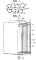
- Fig. 1 is a schematic cross sectional view of one of the negative electrode of an alkaline secondary battery according to the invention.
- Fig. 2 is a schematic cross sectional view of a nickel/hydrate secondary battery according to the invention.
- the inventors of the present invention came to find as a result of research efforts that the property of withstanding overcharging of an alkaline secondary battery is improved by adding a carbonate to the inside of the battery.
- the surface of the hydrogen storing alloy operating as the negative electrode of an alkaline secondary battery is preferably coated with a carbonate-containing compound.
- a hydrogen storing alloy having the AB 2 type crystal structure, the AB type crystal structure or the A 2 B type crystal structure is preferably used.
- Hydrogen storing alloys having the AB 2 type structure that can be used for the purpose of the invention include ZrMn 2 and Zr 0.3 Ti 0.7 Mn 0.5 Ni 1.3 V 0.2 .
- Those having the AB structure include TiNi, TiNi 0.5 V 0.2 Mn 0.3 and those having the A 2 B structure include Mg 2 Ni, Mg 1.6 Al 0.4 Ni 0.8 Mn 0.2 .
- the surface of the hydrogen storing alloy does not have to be covered with a carbonate-containing compound in advance when preparing the hydrogen storing alloy but may be covered with a carbonate-containing compound after assembling the battery to bring forth its effect.
- Methods that can be used for covering the hydrogen storing alloy include adding carbonate of an alkali metal or an alkaline earth metal to the active material of the negative electrode when preparing the battery, adding such carbonate to the active material of the positive electrode, impregnating the separator with such carbonate and dissolving such carbonate in the electrolyte. Then, ions of the carbonate in the electrolyte react with the hydrogen storing alloy to form a layer of a carbonate-containing compound on the surface of the alloy.
- Alkali metals and alkaline earth metals that can be used in the form of carbonate for the purpose of the invention include lithium, sodium, potassium, magnesium, calcium and barium.
- the particle size of the granular carbonate is preferably between 0.1 and 5 ⁇ m.
- the weight ratio of the carbonate relative to the hydrogen storing alloy is between 0.05 and 3wt%, preferably between 0.2 and 1.5wt%, in terms of carbonic acid in the carbonate. The effect of the additive will not be satisfactory if the ratio is lower than the above defined range, whereas carbonic acid ions in the electrolyte will adversely affect the diffusion of hydroxide ions to reduce the high discharging rate of the battery if the ratio is higher than the above range.
- the concentration of the electrolyte of an alkaline secondary battery according to the invention is higher than the ordinary level.
- the concentration of potassium hydroxide is preferably between 34 and 40wt%.
- the use of lithium hydroxide or sodium hydroxide as additive will also be effective because such an additive can substantially compensate the reduction in the hydroxy ion concentration of the electrolyte due to the addition of carbonate.
- nickel hydroxide but also manganese hydroxide may be used as principal ingredient of the positive electrode of an alkaline secondary battery according to the invention.
- the carbonic acid-containing compound on the surface of the hydrogen storing alloy specifically contains CO 3 . More specifically, it can be expressed by formula M 1 (CO 3 ) x ⁇ M 2 (OH) y (where each of M 1 and M 2 represents one or more than one component elements of the hydrogen storing alloy and x and y respectively represent numbers between 0.1 and 4). While it is not clear how the layer of such a compound gives rise to the above identified effect, the effect is particularly remarkable when such a layer is formed on the surface of a hydrogen storing alloy containing any of the elements of Zr, Ti, Ni, Mn, V, Cr, Fe, Co and Al that show the AB 2 type crystal structure.
- the compound reacts with part or all of such elements contained in the alloy to produce carbonates of the elements that are not in a simple form but in the form of basic carbonates containing not only carbonic acid ions but also water and potassium ions composing the electrolyte. Additionally, there are certain metals, each producing at least oxide or hydroxide.
- the sample to which potassium carbonate had not been added revealed no peaks.
- the existence of potassium, manganese and vanadium was confirmed regardless if an aqueous solution of potassium carbonate had been added or not.
- the atoms of those elements presumably had been bound with hydroxyl groups and oxygen atoms when observed through the X-ray photoelectron spectroscope. Only small peaks were detected for zirconium, titanium and nickel respectively.
- a gas chromatography analysis specimens of the above two types of alloy were immersed in a 0.1N aqueous solution of sulfuric acid and the generated gas was analyzed to detect a peak for carbon dioxide from the specimen of alloy to which potassium carbonate had been added.
- the layer of the carbonic acid-containing compound formed on the surface directly reacts with the hydrogen storing alloy to produce metal carbonates and presumably one or more than one metals that are apt to be dissolved into an alkaline aqueous solution or oxidized are eluted to produce basic carbonates of the metals. It is presumable that the basic carbonates of the metals are crystals with a relatively high density and permeable to hydrogen but not to oxygen.
- the rate of permeance of hydrogen gas and oxygen gas through the above hydrogen storing alloy was simulatively determined.
- a specimen of the hydrogen storing alloy having the above composition was immersed in a 30wt% aqueous solution of potassium hydroxide and heated to dissolve the manganese and the vanadium contained in it.
- an aqueous solution of potassium carbonate was added to the above solution to produce basic carbonates of manganese and vanadium.
- the product was then formed into a 1mm thick tablet and a 1:1 mixture of oxygen gas and hydrogen gas was made to flow there through from a side (inlet side) and the composition of the gas coming out from the outlet was analyzed by gas chromatography to find that the hydrogen content was 99%.
- the surface produces basic carbonates of the metals of the alloy that are apt to become hydroxides and/or oxides thereof and the produced carbonates are hardly soluble and dense and hence prevent the alloy from being oxidized further.
- the metals that are not apt to be oxidized are scarcely affected by oxygen gas.
- the metals of the hydrogen storing alloy produce their hydroxides in the electrolyte that is an aqueous alkaline solution such as an aqueous solution of potassium hydroxide or sodium hydroxide. If the metals are oxidized to produce metal oxides, they presumably react with the electrolyte to produce metal hydroxides.
- Such hydroxides are mostly soluble in an aqueous alkaline solution and hence the surface of the metals of the hydrogen storing alloy that can easily be eluted cannot be protected by such hydroxides for a long time. Of course, the metals of the hydrogen storing alloy that can scarcely be eluted or oxidized will practically not be affected.
- Fig. 1 is a schematic cross sectional view of one of the negative electrode of an alkaline secondary battery according to the invention.
- collector 101 takes the form of a piece of punched metal in this embodiment, it may alternatively be a foamed metal, a felt-like metal, an expanded metal or a sheet metal.
- the collector 101 is typically made of nickel or nickel-plated iron, although other conductive metals that are alkali aqueous solution-resistant and electrochemically stable such as copper, stainless steel and titanium may also be used for the purpose of the invention.
- the surface of the hydrogen storing alloy 102 is coated with basic carbonates 103 of the metals that are contained in the hydrogen storing alloy and are apt to be eluted by an alkaline aqueous solution or oxidized.
- a polymeric binder agent 104 is used to bind the hydrogen storing alloy 102 itself and the hydrogen storing alloy 102 and the collector 102.
- the polymeric binder agent may be of a cellulose type or may be made of polyvinyl alcohol, a modified compound of polyvinyl alcohol, vinyl acetate, polytetrafluoroethylene or some other similar substance. Additionally, carbon or nickel may be added to the negative electrode to improve the conductivity of the negative electrode.
- the hydrogen storing alloy is crushed to particles of about 200 mesh or less and the powdered hydrogen storing alloy and the polymeric binder solution are mixed and kneaded well into paste or slurry. Then, the paste or slurry is applied to the punching metal by means of a doctor blade and dried.
- the drying temperature should be such that it does not give rise to decomposition of the binder and/or oxidation of the hydrogen storing alloy and will be about 200°C or less.
- the work is pressed to produce a negative electrode in order to make the surface smooth and dense.
- the above process may be used when the collector is a foamed metal, a felt-like metal, an expanded metal or a sheet metal.
- the binder is made of polytetrafluoroethylene or the like that becomes fibrous to abruptly raise its viscosity, it is preferably applied by means of a roll.
- the particle size of the carbonate of the alkali metal or the alkaline earth metal is preferably between 0.1 and 5 ⁇ m so that particles of the carbonate may enter the inter-granular gaps of the hydrogen storing alloy and fill the gaps effectively without adversely affecting the operation of applying the paste or slurry to the collector.
- the negative electrode may be prepared without using a binder agent. Then, a technique of making fine particles of the hydrogen storing alloy adhere to the collector under pressure and sintering them in a nitrogen or hydrogen atmosphere will be used. Again, this technique may be used when the collector is a foamed metal, a felt-like metal, an expanded metal or a sheet metal. If such is the case and the carbonate is added to the particles of the hydrogen storing alloy, however, the carbonate will be decomposed to produce carbon dioxide gas during the sintering process and become ineffective.
- the positive electrode of a secondary battery according to the invention may be of the so-called sinter type or of the paste type.
- a sinter type positive electrode is prepared by mixing and kneading powdery carbonyl nickel and a cellulose type aqueous binder solution and applying the obtained mixture by means of a doctor blade to the collector, which may be in the form of a punched metal. Then, the applied mixture is dried to produce a porous nickel sinter, which is then immersed into an aqueous solution of nickel salt such as nickel nitrate or nickel sulfate to fill the pores of the sinter with the nickel salt.
- nickel salt such as nickel nitrate or nickel sulfate
- the nickel sinter is immersed into an alkaline aqueous solution such as potassium hydroxide or sodium hydroxide to turn the nickel salt in the pores into nickel hydroxide, which is rigidly held in the pores, before washing and drying the nickel sinter to produce a finished positive electrode.
- an alkaline aqueous solution such as potassium hydroxide or sodium hydroxide
- a paste type positive electrode is prepared by using a collector in the form of a foamed metal or a felt-like metal and filling the pores of the collector with nickel hydroxide.
- a collector in the form of a foamed metal or a felt-like metal and filling the pores of the collector with nickel hydroxide.
- the latter is mixed and kneaded with a binder agent into paste or slurry, which is then applied to the collector by means of a doctor blade or a roll and dried.
- a cobalt compound or some other compound that can improve the performance of the battery may be added to the paste or slurry.
- the carbonate of an alkali metal or that of an alkaline earth metal may be added at this stage of operation to satisfactorily realized the intended effect.
- the particle size of the granular carbonate is preferably between 0.1 and 5 ⁇ m so that particles of the carbonate may fill the gaps effectively without adversely affecting the operation of applying the paste or slurry to the collector.
- the separator of a secondary battery according to the invention plays the role of preventing short-circuiting of the positive and negative electrodes. It may also play the role of holding the electrolyte.
- the separator have to allow hydronium ions and hydroxy ions to move in them and insoluble to the electrolyte. Therefore, a sheet of unwoven fabric of yarned short fibers of nylon, polypropylene or polyethylene may suitably be used for the separator.
- a carbonate compound may be added to the separator by impregnating the separator with an aqueous solution of the carbonate compound and then drying the solution or it may be added to the short fibers that are being yarned before preparing the sheet of unwoven fabric.
- the electrolyte of a secondary battery according to the invention contains an aqueous solution of potassium hydroxide as principal ingredient, to which sodium or lithium is added to a small extent.
- the electrolyte is contained in the separator, the positive electrode and the negative electrode. Particularly, when the carbonate compound is added to a high concentration, the content of the aqueous solution of potassium hydroxide in the electrolyte shall be raised.
- the carbonate compound may be added to the electrolyte when dissolving potassium hydroxide into water for the purpose of the invention.
- an intended electrolyte may be obtained by causing the electrolyte to absorb carbon dioxide gas.
- the carbonate may be produced by heating the paste type negative electrode in an electrochemical process, a chemical process or a combination of such processes.
- the temperature to be used for causing the elements of the hydrogen storing alloy to react with carbonic ions of the added carbonate efficiently is preferably between 40 and 65° C. Then, the effect of the reaction will be remarkable particularly in a charged state.
- a secondary battery according to the invention may show a flat, cylindrical, box-like or sheet-like profile.
- the battery may be of the monolayer type, the multilayer type or the spiral type.
- a spiral type cylindrical battery can be prepared by winding the negative and positive electrodes into a roll with a separator sandwiched therebetween to produce a large surface area for each of the electrodes.
- a secondary battery having such electrodes can allow a large current to flow for charging and discharging.
- a box-like or sheet-like battery can, on the other hand, effectively utilize the internal space for containing the battery of the equipment to be driven by the battery.
- Fig. 2 is a schematic cross sectional view of a spiral type cylindrical secondary battery according to the invention and comprising a negative electrode, a positive electrode, an electrolyte/separator, a battery housing and output terminals.
- a negative electrode 203 there are shown a negative electrode 203, a positive electrode 206, a negative electrode terminal (negative electrode cap or negative electrode can) 208, a positive electrode terminal (positive electrode can or positive electrode cap) 209, an electrolyte/separator 207, a gasket 210, a negative electrode collector 201, a positive electrode collector 204, an insulator plate 211, a negative electrode lead 212, a positive electrode lead 213 and a safety valve 214.
- a positive electrode 206 having a positive electrode active material layer 205 formed on a positive electrode collector 204 and the negative electrode 203 having a negative electrode active material layer 202 formed on a negative electrode collector 201 are oppositely arranged with a separator 207 impregnated at least with an electrolyte inserted therebetween and wound to show a cylindrical multilayer structure having a plurality of windings.
- the cylindrical multilayer structure is contained in a negative electrode can 208 operating as negative electrode terminal.
- a positive electrode cap 209 is provided at the open side of the negative electrode can 208 to operate as positive electrode terminal and a gasket 210 is arranged in another area in the negative electrode can.
- the cylindrical multilayer structure of the electrodes is separated from the positive electrode cap by means of an insulator plate 211.
- the positive electrode 206 is connected to the positive electrode cap 209 by way of a positive electrode lead 213.
- the negative electrode 203 is connected to the negative electrode can 208 by way of a negative electrode lead 212.
- a safety valve 214 is arranged at the side of the positive electrode cap to regulate the internal pressure of the battery.
- the gasket 210 is made of resin selected from fluorine resin, polyamide resin, polysulfone resin and polypropylene resin.
- the battery may be sealed by caulking the assembly as described above by referring to Fig. 2 or, alternatively, by using a sealed glass tube or an adhesive agent, by welding or by soldering.
- the insulator plate 211 of Fig. 2 is typically made of an organic resin material or a ceramic material.
- both the negative electrode can 208 and the positive electrode can 209 are preferably made of stainless steel.
- a titanium-clad stainless steel plate, a copper-clad stainless steel plate or a nickel-plated steel plate is preferable.
- the negative electrode can 208 is not operating as battery case, the latter may be made of a material selected from stainless steel, metals such as zinc, plastics such as polypropylene and composite materials such as that of metal and glass fiber or plastic.
- a battery according to the invention is provided with a safety valve 214 as safety measure that becomes effective when the internal pressure of the battery rises.
- the safety valve may be made of rubber, a spring, a metal ball or a burst foil.
- a hydrogen storing alloy having a composition of LaNi 5 (AB 5 type) was prepared by means of an arc melting furnace.
- the prepared hydrogen storing alloy was crushed to particles of 400 to 200 mesh and used as active material.
- a 10 weight portions of cobalt oxide and a 40 weight portions of 2wt% aqueous solution of methylcellulose were added to a 100 weight portions of commercially available nickel hydroxide and the mixture was kneaded into a pasty state.
- the pasty mixture was then applied to a piece of foamed nickel with a porosity of 94% to fill the pores and subsequently dried at 120°C. Thereafter, the piece of foamed nickel was pressed and cut to predetermined dimensions for the positive electrode.
- a terminal section was prepared on the positive electrode by pressing the piece of foamed nickel at an area thereof in advance so that the pressed area may not be filled with the slurry of nickel hydroxide and then bonding a nickel terminal to that area by means of resistance welding.
- the hydroxide was prepared by adding lithium hydroxide (hydrate) by 1wt% to an 30wt% aqueous solution of potassium hydroxide.
- the separator was made of a 0.15mm thick piece of unwoven fabric of polypropylene.
- the battery was assembled by winding the positive and negative electrodes with the separator sandwiched therebetween.
- the battery case was made of nickel-plated iron.
- the closure was also made of nickel-plated iron and provided with a safety valve. Fluorine resin was used for packing the case.
- the nickel/hydrate secondary battery was activated by repeating twice a cycle of charging it at 0.1CmA for 15 hours and discharging it at 0.2CmA until a final voltage of 1.0V was reached.
- the battery (after the charge/discharge cycles) was disassembled and the negative electrode was washed with water and dried in vacuum before analyzing the surface of the particles of the negative electrode. They were subjected to X-ray photoelectron spectroscopy from the viewpoint of carbon (C1s), oxygen (O1s), metal elements (Ni2p2/3, Lad5/2). Peaks attributable to carbon were found at 286eV and 289eV, of which the peak at 286eV should be that of methylcellulose whereas the peak at 289eV should be that of a metal carbonate. A broad peak attributable to oxygen was found at and near 531eV, which was believed to be attributable to carbonic acid as well as to oxides and hydroxides.
- a peak that seemed to be attributable to a metal was found at 835eV and it was confirmed that the metal was La. As viewed in combination with the effect of carbon, it was believed that there was at least a substance produced as La was chemically bound with carbon. No peak attributable to Ni was found.
- the surface of the particles was observed as they were subjected to Ar etching to find that the peak attributable to carbon was no longer detectable when the etching got to a depth of about 0.15 ⁇ m. On the basis of this fact, it may be safe to presume that there was an about 0.15 ⁇ m thick layer where a carbonate and cellulose coexisted.
- a hydrogen storing alloy having a composition of MmNi 3.5 Co 0.8 Mn 0.4 Al 0.3 (AB 5 type) was prepared in an arc melting furnace.
- a nickel/hydrate secondary battery was prepared as in Example 1 by using the hydrogen storing alloy and activated.
- the surface of the particles of the negative electrode was analyzed as in Example 1.
- the particles were subjected to X-ray photoelectron spectroscopy from the viewpoint of metal elements including Ni, La, Co, Mn and Al. Peaks attributable to carbon and oxygen were substantially same as those of Example 1, although they showed a slight shift. Of the peaks attributable to metals, Mn was the largest owner, followed by Al and La. As viewed in combination with the effect of carbon, it was believed that there was at least a substance produced as Mn was chemically bound with carbon. No peak attributable to Ni or Co was found.
- the surface of the particles was observed as they were subjected to Ar etching to find that the peak attributable to carbon was no longer detectable when the etching got to a depth of about 0.1 ⁇ m. On the basis of this fact, it may be safe to presume that there was an about 0.1 ⁇ m thick layer where a carbonate and cellulose coexisted.
- a hydrogen storing alloy having a composition of ZrMn 2 (AB 2 type) was prepared in an arc melting furnace.
- a nickel/hydrate secondary battery was prepared as in Example 1 by using the hydrogen storing alloy and activated.
- a hydrogen storing alloy having a composition of Zr 0.3 Ti 0.7 Mn 0.5 Ni 1.3 V 0.2 (AB 2 type) was prepared in an arc melting furnace.
- a nickel/hydrate secondary battery was prepared as in Example 1 by using the hydrogen storing alloy and activated.
- the surface of the particles of the negative electrode was analyzed as in Example 1.
- the particles were subjected to X-ray photoelectron spectroscopy from the viewpoint of metal elements including Zr, Ti, Ni, Mn and V. Peaks attributable to carbon and oxygen were substantially same as those of Example 1, although they showed a slight shift. Of the peaks attributable to metals, V was the largest owner, followed by Mn and Ti. As viewed in combination with the effect of carbon, it was believed that there was at least a substance produced as V was chemically bound with carbon. No peak attributable to Zr or Ni was found.
- the surface of the particles was observed as they were subjected to Ar etching to find that the peak attributable to carbon was no longer detectable when the etching got to a depth of about 0.19 ⁇ m. On the basis of this fact, it may be safe to presume that there was an about 0.19 ⁇ m thick layer where a carbonate and cellulose coexisted.
- a hydrogen storing alloy having a composition of TiNi (AB type) was prepared in an arc melting furnace.
- a nickel/hydrate secondary battery was prepared as in Example 1 by using the hydrogen storing alloy and activated.
- a hydrogen storing alloy having a composition of TiNi 0.5 V 0.2 Mn 0.3 (AB type) was prepared in an arc melting furnace.
- a nickel/hydrate secondary battery was prepared as in Example 1 by using the hydrogen storing alloy and activated.
- a hydrogen storing alloy having a composition of Mg 2 Ni (A 2 B type) was prepared in an arc melting furnace.
- a nickel/hydrate secondary battery was prepared as in Example 1 by using the hydrogen storing alloy and activated.
- Potassium carbonate of Example 1 was replaced by lithium carbonate in order to examine the dependency on the type of carbonate.
- a hydrogen storing alloy having a composition of Zr 0.3 Ti 0.7 Mn 0.5 Ni 1.3 V 0.2 was prepared in an arc melting furnace. Otherwise, the process of Example 1 was followed.
- Potassium carbonate of Example 1 was replaced by sodium carbonate in order to examine the dependency on the type of carbonate.
- a hydrogen storing alloy having a composition of Zr 0.3 Ti 0.7 Mn 0.5 Ni 1.3 V 0.2 was prepared in an arc melting furnace. Otherwise, the process of Example 1 was followed.
- Potassium carbonate of Example 1 was replaced by magnesium carbonate in order to examine the dependency on the type of carbonate.
- a hydrogen storing alloy having a composition of Zr 0.3 Ti 0.7 Mn 0.5 Ni 1.3 V 0.2 was prepared in an arc melting furnace. Otherwise, the process of Example 1 was followed.
- Potassium carbonate of Example 1 was replaced by calcium carbonate in order to examine the dependency on the type of carbonate.
- a hydrogen storing alloy having a composition of Zr 0.3 Ti 0.7 Mn 0.5 Ni 1.3 V 0.2 was prepared in an arc melting furnace. Otherwise, the process of Example 1 was followed.
- Example 1 To add potassium carbonate to the positive electrode, nickel hydroxide and cobalt oxide were added simultaneously with it and kneaded in an aqueous solution of methylcellulose. The quantity of the additive was so selected that the performance of the battery was same as it was added to the negative electrode.
- a hydrogen storing alloy having a composition of Zr 0.3 Ti 0.7 Mn 0 . 5 Ni 1.3 V 0.2 was prepared in an arc melting furnace.
- a battery was prepared as in Example 1 except that no potassium carbonate was added to the negative electrode. Otherwise, the process of Example 1 was followed in terms of the conditions of preparing and activating the battery.
- a nylon separator was dipped into a 5wt% aqueous solution of potassium carbonate and dried at 60°C before it was placed in position.
- a hydrogen storing alloy having a composition of Zr 0.3 Ti 0.7 Mn 0.5 Ni 1 . 3 V 0.2 was prepared in an arc melting furnace.
- a battery was prepared as in Example 1 except that no potassium carbonate was added to the negative electrode. Otherwise, the process of Example 1 was followed in terms of the conditions of preparing and activating the battery.
- Potassium carbonate was dissolved into the electrolyte, which was an aqueous solution containing potassium hydroxide by 30wt% and lithium hydroxide by 1.0wt%, by an amount corresponding to the amount added to the negative electrode.
- a hydrogen storing alloy having a composition of Zr 0.3 Ti 0.7 Mn 0.5 Ni 1.3 V 0.2 was prepared in an arc melting furnace.
- a battery was prepared as in Example 1 except that no potassium carbonate was added to the negative electrode. Otherwise, the process of Example 1 was followed in terms of the conditions of preparing and activating the battery.
- Sample batteries were prepared, using different potassium hydroxide concentrations of 34wt% (battery A), 37wt% (battery B), 40wt% (battery C) and 43wt% (battery D) for the respective electrolytes, to each of which lithium hydroxide was added by lwt%.
- a hydrogen storing alloy having a composition of Zr 0.3 Ti 0.7 Mn 0.5 Ni 1.3 V 0.2 was prepared in an arc melting furnace. Otherwise, the process of Example 1 was followed in terms of the conditions of preparing and activating the battery.
- a hydrogen storing alloy having a composition of LaNi 5 (AB 5 type) was prepared in an arc melting furnace.
- a nickel/hydrate secondary battery was prepared as in Example 1 by using the hydrogen storing alloy, to which, however, no potassium carbonate was added, and activated.
- a hydrogen storing alloy having a composition of MmNi 3.5 Co 0.8 Mn 0.4 Al 0.3 (AB 5 type) was prepared in an arc melting furnace.
- a nickel/hydrate secondary battery was prepared as in Example 1 by using the hydrogen storing alloy, to which, however no potassium carbonate was added, and activated.
- a hydrogen storing alloy having a composition of ZrMn 2 (AB 2 type) was prepared in an arc melting furnace.
- a nickel/hydrate secondary battery was prepared as in Example 1 by using the hydrogen storing alloy, to which, however no potassium carbonate was added, and activated.
- a hydrogen storing alloy having a composition of Zr 0.3 Ti 0.7 Mn 0.5 Ni 1.3 V 0.2 (AB 2 type) was prepared in an arc melting furnace.
- a nickel/hydrate secondary battery was prepared as in Example 1 by using the hydrogen storing alloy, to which, however no potassium carbonate was added, and activated.
- a hydrogen storing alloy having a composition of TiNi (AB type) was prepared in an arc melting furnace.
- a nickel/hydrate secondary battery was prepared as in Example 1 by using the hydrogen storing alloy, to which, however no potassium carbonate was added, and activated.
- a hydrogen storing alloy having a composition of TiNi 0.5 V 0.2 Mn 0.3 (AB type) was prepared in an arc melting furnace.
- a nickel/hydrate secondary battery was prepared as in Example 1 by using the hydrogen storing alloy, to which, however no potassium carbonate was added, and activated.
- a hydrogen storing alloy having a composition of Mg 2 Ni (A 2 B type) was prepared in an arc melting furnace.
- a nickel/hydrate secondary battery was prepared as in Example 1 by using the hydrogen storing alloy, to which, however, no potassium carbonate was added, and activated.
- each of the above batteries was subjected to an overcharging and charge/discharge cycles under the following conditions to evaluate the performance.
- the batteries of the examples and those of the comparative examples were compared for performance.
- each of the charged batteries was charged at 0.1CmA continuously for 30 days and discharged at 0.2mA until the final voltage of 1.0V. Thereafter, it was charged at 0.1CmA and discharged at 0.2CmA to see the battery capacity. The discharge capacity was compared with the battery capacity at the second cycle of charge/discharge after activation.
- Table 1 below lists the battery capacity (ratio to the activation capacity) after overcharging and the number of cycles before the fall to 60% of the initial capacity for each of the different hydrogen storing alloys used in the above examples and comparative examples.
- Table 2 below shows the nickel/hydrate secondary batteries of the examples to which lithium carbonate, sodium carbonate, magnesium carbonate and calcium carbonate were added respectively.
- Example 9 Sodium Carbonate 97 1200
- Example 10 Potassium Carbonate 97 1250
- Example 11 Calcium Carbonate 97 1320
Landscapes
- Chemical & Material Sciences (AREA)
- Chemical Kinetics & Catalysis (AREA)
- Electrochemistry (AREA)
- General Chemical & Material Sciences (AREA)
- Engineering & Computer Science (AREA)
- Organic Chemistry (AREA)
- Manufacturing & Machinery (AREA)
- Combustion & Propulsion (AREA)
- Inorganic Chemistry (AREA)
- Battery Electrode And Active Subsutance (AREA)
- Secondary Cells (AREA)
Applications Claiming Priority (2)
| Application Number | Priority Date | Filing Date | Title |
|---|---|---|---|
| JP10048563A JPH11233106A (ja) | 1998-02-16 | 1998-02-16 | アルカリ二次電池およびその製造方法 |
| JP4856398 | 1998-02-16 |
Publications (1)
| Publication Number | Publication Date |
|---|---|
| EP0936686A1 true EP0936686A1 (fr) | 1999-08-18 |
Family
ID=12806869
Family Applications (1)
| Application Number | Title | Priority Date | Filing Date |
|---|---|---|---|
| EP99102690A Withdrawn EP0936686A1 (fr) | 1998-02-16 | 1999-02-12 | Pile de stockage alcaline et méthode pour sa fabrication |
Country Status (4)
| Country | Link |
|---|---|
| US (1) | US6171727B1 (fr) |
| EP (1) | EP0936686A1 (fr) |
| JP (1) | JPH11233106A (fr) |
| KR (1) | KR19990072691A (fr) |
Cited By (4)
| Publication number | Priority date | Publication date | Assignee | Title |
|---|---|---|---|---|
| EP1130666A3 (fr) * | 2000-03-01 | 2004-03-10 | SANYO ELECTRIC Co., Ltd. | Accumulateur alcalin pouvant être utilisé avec stabilité sur une large plage de température |
| WO2005019097A1 (fr) * | 2003-08-19 | 2005-03-03 | Gkss-Forschungszentrum Geesthacht Gmbh | Materiau contenant du metal et accumulant de l'hydrogene et procede de production de ce materiau |
| EP1402593A4 (fr) * | 2001-06-29 | 2009-04-29 | Ovonic Battery Co | Accumulateur hydrogene; electrode positive en nickel; materiau actif d'electrode positive et procedes de fabrication associes |
| CN105731378A (zh) * | 2016-01-26 | 2016-07-06 | 北京科技大学 | 一种有机聚合物/ab5或ab2复合储氢材料及制备方法 |
Families Citing this family (13)
| Publication number | Priority date | Publication date | Assignee | Title |
|---|---|---|---|---|
| US6372383B1 (en) * | 2000-01-31 | 2002-04-16 | Korea Advanced Institute Of Science And Technology | Method for preparing electrodes for Ni/Metal hydride secondary cells using Cu |
| GB0016057D0 (en) * | 2000-06-30 | 2000-08-23 | Aea Technology Plc | A method of assembling a cell |
| JP2002334695A (ja) * | 2001-03-09 | 2002-11-22 | Canon Inc | 二次電池および二次電池の製造方法 |
| EP1313158A3 (fr) * | 2001-11-20 | 2004-09-08 | Canon Kabushiki Kaisha | Materiau d'électrode pour pile rechargeable au lithium, électrode comprenant ce matériau, pile rechargeable au lithium comprenant une telle électrode et procédé de fabrication |
| WO2004086539A1 (fr) * | 2003-03-26 | 2004-10-07 | Canon Kabushiki Kaisha | Materiau d'electrodes pour batterie a lithium secondaire et structure d'electrode comportant ledit materiau |
| US7615314B2 (en) * | 2004-12-10 | 2009-11-10 | Canon Kabushiki Kaisha | Electrode structure for lithium secondary battery and secondary battery having such electrode structure |
| JP2008226537A (ja) * | 2007-03-09 | 2008-09-25 | Sanyo Electric Co Ltd | 非水電解質二次電池及びその製造方法 |
| KR101229229B1 (ko) * | 2010-12-28 | 2013-02-04 | 주식회사 엘지화학 | 원통형 이차전지용 탑 캡 및 이를 포함하는 이차전지 |
| KR101367493B1 (ko) * | 2012-01-30 | 2014-02-26 | 세방전지(주) | 니켈 수소 전지용 전해액 및 이를 포함하는 니켈 수소 전지 |
| US9450233B2 (en) * | 2013-02-06 | 2016-09-20 | Encell Technology, Inc. | Battery comprising a coated iron anode |
| US10868338B2 (en) | 2013-02-06 | 2020-12-15 | Encell Technology, Inc. | Nickel-iron battery with high power |
| US10854926B2 (en) | 2013-02-06 | 2020-12-01 | Encell Technology, Inc. | Nickel-iron battery with high cycle life |
| WO2015118691A1 (fr) * | 2014-02-10 | 2015-08-13 | エクセルギー・パワー・システムズ株式会社 | Accumulateur alcalin |
Citations (2)
| Publication number | Priority date | Publication date | Assignee | Title |
|---|---|---|---|---|
| JPH04121960A (ja) * | 1990-09-10 | 1992-04-22 | Sanyo Electric Co Ltd | 水素吸蔵合金電極の製造方法 |
| EP0645833A1 (fr) * | 1993-08-31 | 1995-03-29 | SANYO ELECTRIC Co., Ltd. | Procédé de fabrication d'une électrode en alliage absorbant l'hydrogène |
Family Cites Families (8)
| Publication number | Priority date | Publication date | Assignee | Title |
|---|---|---|---|---|
| JPH05135763A (ja) | 1991-11-11 | 1993-06-01 | Matsushita Electric Ind Co Ltd | アルカリ蓄電池 |
| JPH06163072A (ja) | 1992-11-19 | 1994-06-10 | Sanyo Electric Co Ltd | 金属・水素化物二次電池 |
| JP3499923B2 (ja) | 1994-07-15 | 2004-02-23 | 三洋電機株式会社 | 金属−水素化物アルカリ蓄電池用の水素吸蔵合金電極及び金属−水素化物アルカリ蓄電池用の水素吸蔵合金粒子 |
| JPH0864245A (ja) * | 1994-08-25 | 1996-03-08 | Fuji Photo Film Co Ltd | 非水電解質電池 |
| JPH08138658A (ja) | 1994-09-12 | 1996-05-31 | Furukawa Battery Co Ltd:The | 水素吸蔵合金電極 |
| JPH08250099A (ja) | 1995-03-13 | 1996-09-27 | Toshiba Battery Co Ltd | ニッケル水素二次電池 |
| JPH0963644A (ja) * | 1995-06-13 | 1997-03-07 | Mitsui Petrochem Ind Ltd | 非水電解液及び非水電解液電池 |
| JPH0945331A (ja) | 1995-08-02 | 1997-02-14 | Furukawa Electric Co Ltd:The | 水素吸蔵合金電極とそれを用いたニッケル・水素二次電池 |
-
1998
- 1998-02-16 JP JP10048563A patent/JPH11233106A/ja active Pending
-
1999
- 1999-02-12 EP EP99102690A patent/EP0936686A1/fr not_active Withdrawn
- 1999-02-13 KR KR1019990005320A patent/KR19990072691A/ko not_active Abandoned
- 1999-02-16 US US09/250,489 patent/US6171727B1/en not_active Expired - Fee Related
Patent Citations (2)
| Publication number | Priority date | Publication date | Assignee | Title |
|---|---|---|---|---|
| JPH04121960A (ja) * | 1990-09-10 | 1992-04-22 | Sanyo Electric Co Ltd | 水素吸蔵合金電極の製造方法 |
| EP0645833A1 (fr) * | 1993-08-31 | 1995-03-29 | SANYO ELECTRIC Co., Ltd. | Procédé de fabrication d'une électrode en alliage absorbant l'hydrogène |
Non-Patent Citations (1)
| Title |
|---|
| PATENT ABSTRACTS OF JAPAN vol. 016, no. 381 (E - 1248) 14 August 1992 (1992-08-14) * |
Cited By (7)
| Publication number | Priority date | Publication date | Assignee | Title |
|---|---|---|---|---|
| EP1130666A3 (fr) * | 2000-03-01 | 2004-03-10 | SANYO ELECTRIC Co., Ltd. | Accumulateur alcalin pouvant être utilisé avec stabilité sur une large plage de température |
| EP1402593A4 (fr) * | 2001-06-29 | 2009-04-29 | Ovonic Battery Co | Accumulateur hydrogene; electrode positive en nickel; materiau actif d'electrode positive et procedes de fabrication associes |
| WO2005019097A1 (fr) * | 2003-08-19 | 2005-03-03 | Gkss-Forschungszentrum Geesthacht Gmbh | Materiau contenant du metal et accumulant de l'hydrogene et procede de production de ce materiau |
| DE10337970B4 (de) * | 2003-08-19 | 2009-04-23 | Gkss-Forschungszentrum Geesthacht Gmbh | Metallhaltiger, wasserstoffspeichernder Werkstoff und Verfahren zu seiner Herstellung |
| US7833928B2 (en) | 2003-08-19 | 2010-11-16 | Gkss-Forschungszentrum Geesthacht Gmbh | Metalliferous, hydrogen-storing material and process for its production |
| CN105731378A (zh) * | 2016-01-26 | 2016-07-06 | 北京科技大学 | 一种有机聚合物/ab5或ab2复合储氢材料及制备方法 |
| CN105731378B (zh) * | 2016-01-26 | 2018-07-24 | 北京科技大学 | 一种有机聚合物/ab5或ab2复合储氢材料及制备方法 |
Also Published As
| Publication number | Publication date |
|---|---|
| KR19990072691A (ko) | 1999-09-27 |
| JPH11233106A (ja) | 1999-08-27 |
| US6171727B1 (en) | 2001-01-09 |
Similar Documents
| Publication | Publication Date | Title |
|---|---|---|
| US6171727B1 (en) | Alkaline secondary battery and method of manufacturing the same | |
| EP1164650B1 (fr) | Batterie rechargeable au nickel et procédé pour sa production | |
| US7527890B2 (en) | Sealed alkaline storage battery, electrode structure and charging method for the same, and charger for sealed alkaline storage battery | |
| EP1172869B1 (fr) | Méthode de production de matière active positive pour une batterie alcaline | |
| KR100281729B1 (ko) | 니켈 양극 및 이것을 사용한 알칼리 축전지 | |
| KR100386519B1 (ko) | 알칼리축전지용비소결식니켈극 | |
| JP2007509480A (ja) | 電極、その製造方法、金属/空気燃料セルおよび金属水素化物セル | |
| JP2009518795A (ja) | 2機能性空気電極 | |
| JPWO2003021698A1 (ja) | ニッケル電極材料及びその製造方法、並びに、ニッケル電極及びアルカリ蓄電池 | |
| EP1367666A1 (fr) | Procede de fabrication d'une batterie nickel-hydrogene | |
| JPH10275631A (ja) | 粉末材料、電極構造体、それらの製造方法及び二次電池 | |
| JP5350110B2 (ja) | アルカリ蓄電池用ニッケル電極およびアルカリ蓄電池 | |
| JP4533216B2 (ja) | 粉末材料、電極構造体、それらの製造方法及び二次電池 | |
| JP2001076730A (ja) | ニッケル−水素二次電池 | |
| JP2003249222A (ja) | ニッケル・水素蓄電池 | |
| US20040248005A1 (en) | Negative electrodes including highly active, high surface area hydrogen storage material for use in electrochemical cells | |
| JP2000080429A (ja) | 水素吸蔵合金および二次電池 | |
| JP2000340221A (ja) | ニッケル電極およびそれを正極に用いたニッケル水素蓄電池 | |
| JP2008235173A (ja) | ニッケル水素二次電池 | |
| JP2017143053A (ja) | 電池およびその製造方法 | |
| EP4597618A1 (fr) | Électrode négative pour batteries secondaires alcalines, batterie secondaire alcaline et procédé de production d'électrode négative pour batteries secondaires alcalines | |
| JP2007173220A (ja) | アルカリ電池およびその製造方法 | |
| US20060234129A1 (en) | Batteries utilizing a solid polymeric electrolyte | |
| EP4131530A1 (fr) | Batterie plate et son procédé de fabrication | |
| JPH10241643A (ja) | 水素化物二次電池 |
Legal Events
| Date | Code | Title | Description |
|---|---|---|---|
| PUAI | Public reference made under article 153(3) epc to a published international application that has entered the european phase |
Free format text: ORIGINAL CODE: 0009012 |
|
| AK | Designated contracting states |
Kind code of ref document: A1 Designated state(s): DE FR GB IT NL |
|
| AX | Request for extension of the european patent |
Free format text: AL;LT;LV;MK;RO;SI |
|
| 17P | Request for examination filed |
Effective date: 20000217 |
|
| AKX | Designation fees paid |
Free format text: DE FR GB IT NL |
|
| 17Q | First examination report despatched |
Effective date: 20010712 |
|
| STAA | Information on the status of an ep patent application or granted ep patent |
Free format text: STATUS: THE APPLICATION IS DEEMED TO BE WITHDRAWN |
|
| 18D | Application deemed to be withdrawn |
Effective date: 20020115 |