EP0937806A2 - Dispositif pour faire passer en continu un gaz de traitement à travers une matière textile ou analogue - Google Patents
Dispositif pour faire passer en continu un gaz de traitement à travers une matière textile ou analogue Download PDFInfo
- Publication number
- EP0937806A2 EP0937806A2 EP99103271A EP99103271A EP0937806A2 EP 0937806 A2 EP0937806 A2 EP 0937806A2 EP 99103271 A EP99103271 A EP 99103271A EP 99103271 A EP99103271 A EP 99103271A EP 0937806 A2 EP0937806 A2 EP 0937806A2
- Authority
- EP
- European Patent Office
- Prior art keywords
- metal strips
- clamping
- sheet metal
- drum
- clamping groove
- Prior art date
- Legal status (The legal status is an assumption and is not a legal conclusion. Google has not performed a legal analysis and makes no representation as to the accuracy of the status listed.)
- Granted
Links
Images

Classifications
-
- F—MECHANICAL ENGINEERING; LIGHTING; HEATING; WEAPONS; BLASTING
- F26—DRYING
- F26B—DRYING SOLID MATERIALS OR OBJECTS BY REMOVING LIQUID THEREFROM
- F26B13/00—Machines and apparatus for drying fabrics, fibres, yarns, or other materials in long lengths, with progressive movement
- F26B13/10—Arrangements for feeding, heating or supporting materials; Controlling movement, tension or position of materials
- F26B13/14—Rollers, drums, cylinders; Arrangement of drives, supports, bearings, cleaning
- F26B13/16—Rollers, drums, cylinders; Arrangement of drives, supports, bearings, cleaning perforated in combination with hot air blowing or suction devices, e.g. sieve drum dryers
-
- D—TEXTILES; PAPER
- D06—TREATMENT OF TEXTILES OR THE LIKE; LAUNDERING; FLEXIBLE MATERIALS NOT OTHERWISE PROVIDED FOR
- D06B—TREATING TEXTILE MATERIALS USING LIQUIDS, GASES OR VAPOURS
- D06B23/00—Component parts, details, or accessories of apparatus or machines, specially adapted for the treating of textile materials, not restricted to a particular kind of apparatus, provided for in groups D06B1/00 - D06B21/00
- D06B23/02—Rollers
- D06B23/025—Perforated rollers
-
- D—TEXTILES; PAPER
- D21—PAPER-MAKING; PRODUCTION OF CELLULOSE
- D21F—PAPER-MAKING MACHINES; METHODS OF PRODUCING PAPER THEREON
- D21F5/00—Dryer section of machines for making continuous webs of paper
- D21F5/18—Drying webs by hot air
- D21F5/182—Drying webs by hot air through perforated cylinders
Definitions
- the invention relates to a device for flowing, continuous Treatment of web-like textile goods, nonwovens or paper with a gaseous one in the device circulated treatment agent, with a suction standing permeable drum with bottoms on the front as a transport element, which is covered with a sieve-shaped or perforated covering on its circumference is, sheet metal strips firmly connected to the bottoms between the bottoms of the drum extend from floor to floor, the width of which extends in radial Direction stretched.
- a device of this type is known from DE 38 21 330 A1. It has the advantage that it is optimally permeable to air without reducing the stability of the drum is. Another advantage is the screw construction realized on this device. Without having to resort to the previously known welded construction, In this way, all drum casing elements are screwed on the bridge connections through the connecting webs running in the circumferential direction the sheet metal strip extending longitudinally over the drum all over the drum firmly connected. The disadvantageous structural changes in the metal in the Manufacturing of otherwise necessary weld seams are with this screw construction avoided.
- the connection of the metal strips with the bottoms of the Drum once with a bottom and once with the nozzle star through which the Fan sets the interior of the drum under suction when in use exposed to greater thermal loads in practice.
- the floors have a larger one Heat capacity than the metal strips. If when a cold good comes in the heated drum housing shocked the metal strips when they came into contact with the goods cool down, this initially does not apply to the floors, so that there are greater tensions in the material that cause cracks or dents on the drum. This is regardless of the drum construction, i.e. whether it is welded or screwed.
- the invention is based on the tasks, a connection between the metal strips and to create the adjacent bottom of the drum, which takes advantage of combines the two types of fastening mentioned, but avoids their disadvantages.
- the invention provides for solving the problem that the sheet metal strips over their entire radially aligned height is fixed, but detachable with the assigned floors are connected. This is advantageously possible with a clamp connection that Strips stuck firmly over their entire height.
- a conceivable constructive solution is given when the bottom in the radial height of the arrangement of the metal strips for each two sheet metal strips has a radially aligned clamping groove, the opening cross section corresponds to the distance between the two adjacent metal strips.
- a screen drum device basically consists of an approximately rectangular housing 1, through an intermediate wall 2 into a treatment room 3 and Fan room 4 is divided.
- the screening drum 5 is concentric to this a fan 6 rotatably mounted in the fan chamber 4.
- the fan chamber can also be in one of the screen drum housing 1 separate, not shown, arranged separate fan housing his. In any case, the fan draws the inside of the drum 5. Is too the drum construction on a wet treatment device, which is also only for suction of liquid can be the subject of the patent. The overall construction must then be adjusted accordingly.
- heating units 7 above and below the fan 6 which consist of pipes through which heating medium flows.
- the sieve drum is in the area not covered by the textile material 10 on the inside of a not shown Inner cover covered against the induced draft.
- the carrying the textile 10 Sheath structure of the screen drum is due to the sheet metal strip structure described below educated. This is surrounded on the outside by a fine-mesh sieve 9, that with the front of the drum on the bottom 12 and on the bottom 11 the nozzle star 11 'is kept tense.
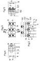
- the sheet metal strip structure consists of axially aligned sheet metal strips 13, the radial of which aligned height emerges from Figures 3-5. So that's it Sieve-shaped covering 9 according to FIG. 1 only on the radially outer edges of the Sheet metal strip 13.
- the sheet metal strips 13 are side by side according to FIG. 2 with a defined distance attached to the two floors 11, 12. The distance is determined by the length of the between all sheet metal strips 13 to be arranged connecting webs 14 determined by the ultimately screws 15, 16 are pushed through for all-round fastening.
- For axial Fastening the sheet metal strips 13 to the bottoms 11, 12 serves a clamping construction, which holds the metal strips 13 over their entire radial height.
- the clamp construction is introduced in a separate centering ring 17, which in turn via screws 18th is connected to the respective floor 11, 12.
- the attachment of the centering ring 17th on the associated floor 11, 12 by means of the screws 18 takes place alternately Fastening the metal strips 13 to the centering ring 17 by means of the screws 23, 24, see FIGS. 2 and 3.
Landscapes
- Engineering & Computer Science (AREA)
- Textile Engineering (AREA)
- Mechanical Engineering (AREA)
- General Engineering & Computer Science (AREA)
- Treatment Of Fiber Materials (AREA)
Applications Claiming Priority (2)
| Application Number | Priority Date | Filing Date | Title |
|---|---|---|---|
| DE19806614A DE19806614A1 (de) | 1998-02-18 | 1998-02-18 | Vorrichtung zum durchströmenden, kontinuierlichen Behandeln von Textilgut o. dgl. |
| DE19806614 | 1998-02-18 |
Publications (3)
| Publication Number | Publication Date |
|---|---|
| EP0937806A2 true EP0937806A2 (fr) | 1999-08-25 |
| EP0937806A3 EP0937806A3 (fr) | 2000-05-24 |
| EP0937806B1 EP0937806B1 (fr) | 2003-05-07 |
Family
ID=7858061
Family Applications (1)
| Application Number | Title | Priority Date | Filing Date |
|---|---|---|---|
| EP99103271A Expired - Lifetime EP0937806B1 (fr) | 1998-02-18 | 1999-02-13 | Dispositif pour faire passer en continu un gaz de traitement à travers une matière textile ou analogue |
Country Status (3)
| Country | Link |
|---|---|
| US (1) | US6088927A (fr) |
| EP (1) | EP0937806B1 (fr) |
| DE (2) | DE19806614A1 (fr) |
Cited By (1)
| Publication number | Priority date | Publication date | Assignee | Title |
|---|---|---|---|---|
| JP2004504505A (ja) * | 2000-07-18 | 2004-02-12 | フライスナー ゲゼルシャフト ミット ベシュレンクテル ハフツング ウント コンパニー マシーネンファブリーク | 繊維製品又はそれに類似したものを貫流する処理媒体で連続的に処理するための装置 |
Families Citing this family (1)
| Publication number | Priority date | Publication date | Assignee | Title |
|---|---|---|---|---|
| ITBO20020369A1 (it) * | 2002-06-12 | 2003-12-12 | Marposs Spa | Apparecchiatura per il controllo di caratteristiche dimensionali e geometriche di perni |
Family Cites Families (4)
| Publication number | Priority date | Publication date | Assignee | Title |
|---|---|---|---|---|
| DE3802791A1 (de) * | 1988-01-30 | 1989-08-10 | Fleissner Maschf Ag | Vorrichtung zum durchstroemenden behandeln von textilgut, papier od. dgl. |
| DE3821330A1 (de) * | 1988-01-30 | 1989-12-28 | Fleissner Maschf Ag | Vorrichtung zum durchstroemenden behandeln von textilgut, papier od. dgl. |
| DE3907421A1 (de) * | 1989-03-08 | 1990-09-20 | Fleissner Maschf Ag | Vorrichtung zum durchstroemenden behandeln von textilgut, papier od. dgl. |
| DE4422508C1 (de) * | 1994-06-28 | 1996-02-15 | Fleissner Maschf Gmbh Co | Vorrichtung zum durchströmenden Behandeln von Textilgut od. dgl. |
-
1998
- 1998-02-18 DE DE19806614A patent/DE19806614A1/de not_active Withdrawn
-
1999
- 1999-02-13 EP EP99103271A patent/EP0937806B1/fr not_active Expired - Lifetime
- 1999-02-13 DE DE59905386T patent/DE59905386D1/de not_active Expired - Fee Related
- 1999-02-18 US US09/251,726 patent/US6088927A/en not_active Expired - Lifetime
Cited By (1)
| Publication number | Priority date | Publication date | Assignee | Title |
|---|---|---|---|---|
| JP2004504505A (ja) * | 2000-07-18 | 2004-02-12 | フライスナー ゲゼルシャフト ミット ベシュレンクテル ハフツング ウント コンパニー マシーネンファブリーク | 繊維製品又はそれに類似したものを貫流する処理媒体で連続的に処理するための装置 |
Also Published As
| Publication number | Publication date |
|---|---|
| EP0937806B1 (fr) | 2003-05-07 |
| EP0937806A3 (fr) | 2000-05-24 |
| DE19806614A1 (de) | 1999-08-19 |
| US6088927A (en) | 2000-07-18 |
| DE59905386D1 (de) | 2003-06-12 |
Similar Documents
| Publication | Publication Date | Title |
|---|---|---|
| DE4422508C1 (de) | Vorrichtung zum durchströmenden Behandeln von Textilgut od. dgl. | |
| EP0841424B1 (fr) | Dispositif pour l'aiguilletage hydraulique d'étoffes non-tissées, tissus | |
| DE2342421C3 (de) | Trommel mit einer ringförmigen Gitterkonstruktion | |
| DE2436684C2 (de) | Vorrichtung zum gleichmäßigeren adiabatischen Trocknen von aus mehreren feuerfesten Schichten aufgebauten Schalenformen an verlorenen Modellen | |
| EP0678613B1 (fr) | Dispositif pour forcer un fluide de traitement à travers une matière textile | |
| DE3907421C2 (fr) | ||
| EP0937806B1 (fr) | Dispositif pour faire passer en continu un gaz de traitement à travers une matière textile ou analogue | |
| EP0315961B1 (fr) | Appareil pour forcer un fluide de traitement à travers une matière textile | |
| EP0753619A2 (fr) | Dispositif pour faire passer un fluide de traitement à travers une matière textile ou analogue | |
| DE10001535A1 (de) | Vorrichtung vorzugsweise zum hydrodynamischen Vernadeln von z. B. Vliesen, Tissue oder Papier mit einer Blechtrommel als Unterstützungselement für das Gut | |
| EP1563134B1 (fr) | Dispositif de traitement d'articles en forme de bande par ecoulement et application de pression | |
| EP1301659B1 (fr) | Dispositif permettant de traiter en continu, par passage, des produits textiles ou similaires | |
| EP3159446A2 (fr) | Dispositif de traitement thermique d'une nappe de tissu textile | |
| DE3802791A1 (de) | Vorrichtung zum durchstroemenden behandeln von textilgut, papier od. dgl. | |
| EP0950747A1 (fr) | Dispositif pour faire passer en continu un fluide chaud de traitement à travers une matière textile ou analogue | |
| EP0385208B1 (fr) | Appareil pour faire passer un fluide de traitement à travers une matière textile | |
| DE10111335A1 (de) | Trommelvorrichtung mit durchlässigem Trommelmantel und gespannt aufgezogenem Siebgewebe | |
| DE10307074A1 (de) | Vorrichtung mit einer von einem Fluid radial durchströmten Siebtrommel und einem diese umgebenden durchlässigen Belag | |
| DE3821330A1 (de) | Vorrichtung zum durchstroemenden behandeln von textilgut, papier od. dgl. | |
| DE19836027A1 (de) | Vorrichtung zum durchströmenden, kontinuierlichen Wärmebehandeln von Textilgut, Tissue o. dgl. | |
| EP3556922A1 (fr) | Dispositif de traitement thermique d'une bande de matière textile | |
| DE3835729A1 (de) | Vorrichtung zum durchstroemenden behandeln von textilgut und dgl. | |
| EP1685287B1 (fr) | Dispositif monte sur un tambour tamiseur traverse de l'exterieur vers l'interieur | |
| DE1635123C3 (de) | Vorrichtung zum kontinuierlichen Wärmebehandeln, wie Trocknen, Dämpfen oder Farbstoff-Fixieren von bahnförmigen Gütern | |
| DE3738117A1 (de) | Vorrichtung zum durchstroemenden behandeln von textilgut od. dgl. |
Legal Events
| Date | Code | Title | Description |
|---|---|---|---|
| PUAI | Public reference made under article 153(3) epc to a published international application that has entered the european phase |
Free format text: ORIGINAL CODE: 0009012 |
|
| AK | Designated contracting states |
Kind code of ref document: A2 Designated state(s): DE FR GB IT |
|
| AX | Request for extension of the european patent |
Free format text: AL;LT;LV;MK;RO;SI |
|
| PUAL | Search report despatched |
Free format text: ORIGINAL CODE: 0009013 |
|
| AK | Designated contracting states |
Kind code of ref document: A3 Designated state(s): AT BE CH CY DE DK ES FI FR GB GR IE IT LI LU MC NL PT SE |
|
| AX | Request for extension of the european patent |
Free format text: AL;LT;LV;MK;RO;SI |
|
| 17P | Request for examination filed |
Effective date: 20000529 |
|
| AKX | Designation fees paid |
Free format text: DE FI FR GB |
|
| RBV | Designated contracting states (corrected) |
Designated state(s): DE FR GB IT |
|
| 17Q | First examination report despatched |
Effective date: 20020611 |
|
| GRAH | Despatch of communication of intention to grant a patent |
Free format text: ORIGINAL CODE: EPIDOS IGRA |
|
| GRAH | Despatch of communication of intention to grant a patent |
Free format text: ORIGINAL CODE: EPIDOS IGRA |
|
| GRAA | (expected) grant |
Free format text: ORIGINAL CODE: 0009210 |
|
| AK | Designated contracting states |
Designated state(s): DE FR GB IT |
|
| REG | Reference to a national code |
Ref country code: GB Ref legal event code: FG4D Free format text: NOT ENGLISH |
|
| REF | Corresponds to: |
Ref document number: 59905386 Country of ref document: DE Date of ref document: 20030612 Kind code of ref document: P |
|
| GBT | Gb: translation of ep patent filed (gb section 77(6)(a)/1977) | ||
| ET | Fr: translation filed | ||
| PLBE | No opposition filed within time limit |
Free format text: ORIGINAL CODE: 0009261 |
|
| STAA | Information on the status of an ep patent application or granted ep patent |
Free format text: STATUS: NO OPPOSITION FILED WITHIN TIME LIMIT |
|
| 26N | No opposition filed |
Effective date: 20040210 |
|
| PGFP | Annual fee paid to national office [announced via postgrant information from national office to epo] |
Ref country code: GB Payment date: 20080219 Year of fee payment: 10 |
|
| PGFP | Annual fee paid to national office [announced via postgrant information from national office to epo] |
Ref country code: DE Payment date: 20090227 Year of fee payment: 11 |
|
| PGFP | Annual fee paid to national office [announced via postgrant information from national office to epo] |
Ref country code: IT Payment date: 20090219 Year of fee payment: 11 |
|
| GBPC | Gb: european patent ceased through non-payment of renewal fee |
Effective date: 20090213 |
|
| PGFP | Annual fee paid to national office [announced via postgrant information from national office to epo] |
Ref country code: FR Payment date: 20090219 Year of fee payment: 11 |
|
| PG25 | Lapsed in a contracting state [announced via postgrant information from national office to epo] |
Ref country code: GB Free format text: LAPSE BECAUSE OF NON-PAYMENT OF DUE FEES Effective date: 20090213 |
|
| REG | Reference to a national code |
Ref country code: FR Ref legal event code: ST Effective date: 20101029 |
|
| PG25 | Lapsed in a contracting state [announced via postgrant information from national office to epo] |
Ref country code: FR Free format text: LAPSE BECAUSE OF NON-PAYMENT OF DUE FEES Effective date: 20100301 |
|
| PG25 | Lapsed in a contracting state [announced via postgrant information from national office to epo] |
Ref country code: DE Free format text: LAPSE BECAUSE OF NON-PAYMENT OF DUE FEES Effective date: 20100901 |
|
| PG25 | Lapsed in a contracting state [announced via postgrant information from national office to epo] |
Ref country code: IT Free format text: LAPSE BECAUSE OF NON-PAYMENT OF DUE FEES Effective date: 20100213 |