EP0939414A1 - Beleuchtete Taste und Verfahren zu ihrer Herstellung - Google Patents
Beleuchtete Taste und Verfahren zu ihrer Herstellung Download PDFInfo
- Publication number
- EP0939414A1 EP0939414A1 EP99110963A EP99110963A EP0939414A1 EP 0939414 A1 EP0939414 A1 EP 0939414A1 EP 99110963 A EP99110963 A EP 99110963A EP 99110963 A EP99110963 A EP 99110963A EP 0939414 A1 EP0939414 A1 EP 0939414A1
- Authority
- EP
- European Patent Office
- Prior art keywords
- key
- key top
- transparent
- keytop
- operating portion
- Prior art date
- Legal status (The legal status is an assumption and is not a legal conclusion. Google has not performed a legal analysis and makes no representation as to the accuracy of the status listed.)
- Granted
Links
Images




Classifications
-
- H—ELECTRICITY
- H01—ELECTRIC ELEMENTS
- H01H—ELECTRIC SWITCHES; RELAYS; SELECTORS; EMERGENCY PROTECTIVE DEVICES
- H01H13/00—Switches having rectilinearly-movable operating part or parts adapted for pushing or pulling in one direction only, e.g. push-button switch
- H01H13/70—Switches having rectilinearly-movable operating part or parts adapted for pushing or pulling in one direction only, e.g. push-button switch having a plurality of operating members associated with different sets of contacts, e.g. keyboard
- H01H13/702—Switches having rectilinearly-movable operating part or parts adapted for pushing or pulling in one direction only, e.g. push-button switch having a plurality of operating members associated with different sets of contacts, e.g. keyboard with contacts carried by or formed from layers in a multilayer structure, e.g. membrane switches
- H01H13/705—Switches having rectilinearly-movable operating part or parts adapted for pushing or pulling in one direction only, e.g. push-button switch having a plurality of operating members associated with different sets of contacts, e.g. keyboard with contacts carried by or formed from layers in a multilayer structure, e.g. membrane switches characterised by construction, mounting or arrangement of operating parts, e.g. push-buttons or keys
-
- H—ELECTRICITY
- H01—ELECTRIC ELEMENTS
- H01H—ELECTRIC SWITCHES; RELAYS; SELECTORS; EMERGENCY PROTECTIVE DEVICES
- H01H9/00—Details of switching devices, not covered by groups H01H1/00 - H01H7/00
- H01H9/18—Distinguishing marks on switches, e.g. for indicating switch location in the dark; Adaptation of switches to receive distinguishing marks
- H01H2009/187—Distinguishing marks on switches, e.g. for indicating switch location in the dark; Adaptation of switches to receive distinguishing marks having symbols engraved or printed by laser
-
- H—ELECTRICITY
- H01—ELECTRIC ELEMENTS
- H01H—ELECTRIC SWITCHES; RELAYS; SELECTORS; EMERGENCY PROTECTIVE DEVICES
- H01H2209/00—Layers
- H01H2209/002—Materials
-
- H—ELECTRICITY
- H01—ELECTRIC ELEMENTS
- H01H—ELECTRIC SWITCHES; RELAYS; SELECTORS; EMERGENCY PROTECTIVE DEVICES
- H01H2209/00—Layers
- H01H2209/006—Force isolators
-
- H—ELECTRICITY
- H01—ELECTRIC ELEMENTS
- H01H—ELECTRIC SWITCHES; RELAYS; SELECTORS; EMERGENCY PROTECTIVE DEVICES
- H01H2209/00—Layers
- H01H2209/016—Protection layer, e.g. for legend, anti-scratch
-
- H—ELECTRICITY
- H01—ELECTRIC ELEMENTS
- H01H—ELECTRIC SWITCHES; RELAYS; SELECTORS; EMERGENCY PROTECTIVE DEVICES
- H01H2209/00—Layers
- H01H2209/068—Properties of the membrane
- H01H2209/082—Properties of the membrane transparent
-
- H—ELECTRICITY
- H01—ELECTRIC ELEMENTS
- H01H—ELECTRIC SWITCHES; RELAYS; SELECTORS; EMERGENCY PROTECTIVE DEVICES
- H01H2219/00—Legends
- H01H2219/028—Printed information
-
- H—ELECTRICITY
- H01—ELECTRIC ELEMENTS
- H01H—ELECTRIC SWITCHES; RELAYS; SELECTORS; EMERGENCY PROTECTIVE DEVICES
- H01H2221/00—Actuators
- H01H2221/002—Actuators integral with membrane
- H01H2221/006—Adhesive
-
- H—ELECTRICITY
- H01—ELECTRIC ELEMENTS
- H01H—ELECTRIC SWITCHES; RELAYS; SELECTORS; EMERGENCY PROTECTIVE DEVICES
- H01H2221/00—Actuators
- H01H2221/05—Force concentrator; Actuating dimple
-
- H—ELECTRICITY
- H01—ELECTRIC ELEMENTS
- H01H—ELECTRIC SWITCHES; RELAYS; SELECTORS; EMERGENCY PROTECTIVE DEVICES
- H01H2221/00—Actuators
- H01H2221/07—Actuators transparent
-
- H—ELECTRICITY
- H01—ELECTRIC ELEMENTS
- H01H—ELECTRIC SWITCHES; RELAYS; SELECTORS; EMERGENCY PROTECTIVE DEVICES
- H01H2227/00—Dimensions; Characteristics
- H01H2227/002—Layer thickness
Definitions
- the present invention relates to an illumination key for use in various mobile communication devices, such as cellular phones and automobile phones, and various terminal devices, such as electronic organizers and the like, to enable the keys thereof to be visible in nighttime and low light conditions.
- the present invention further relates to a method of manufacturing such illumination key.
- this type of illumination key is constructed by forming a printed pattern layer, such as a character or the like, into the underside surface of a key top made of light-permeable resin and then fixing a silicon rubber key operating portion to the back side of the printed pattern layer by means of silicon rubber and an adhesive having good adhesive properties.
- the printed pattern (character) layer is formed in the underside surface of the light-permeable resin key top, the printed pattern (character) is difficult to see in the illumination key described above in the case where the upper surface of the key top has a curved shape.
- an object of the present invention to provide an illumination key which makes it possible to reliably recognize a printed pattern (character) on upper side of the key top even when the upper surface of the key top is slanted or curved, in which a key operating portion is given a rubber-like click sensitivity and a rubber-like elasticity, the key top portion is made from a rigid resin, and a reliably strong bond iscreated between the key operating portion and the key top.
- an object of the present invention to provide an illumination key that can reliably achieve ON/OFF operations while making it possible to reduce the weight of the keytop without reducing the bonding strength between the keytop and the key operating portion.
- the illumination key it is possible to form a partial transmission type light reflection membrane having a white color or the like on all surfaces excluding the underside surface of the light-permeable resin key top, with the printed pattern (character) layer being formed in the upper surface of such a partial transmission type reflection membrane.
- the printed pattern (character) portion except for the printed pattern (character) portion, an opaque layer is provided to cover the upper and side surfaces of the key top, with the upper and side surfaces of the opaque layer being covered by a transparent protection layer.
- a transparent adhesive is used to fix the underside surface of the key top to the upper surface of a key operating portion made of light-permeable silicon rubber or thermoplastic elastomer.
- the illumination key it is possible to use a thin key top made from a white -colored or a colored partial light-permeable resin, with the printed pattern (character) being formed on a surface of the key top which excludes the underside thereof.
- a transparent adhesive is used to fix the underside surface of the key top to the upper surface of a key operating portion made of light-permeable silicon rubber or thermoplastic elastomer.
- an operating shaft is formed at a central portion of the underside of a transparent resin keytop mounted and bonded on top of a key operating portion formed from a transparent rubber or thermoplastic elastomer, and a cavity portion is formed in the underside of the keytops in order to make the keytop thinner.
- the transparent resin keytop formed with the operating shaft is formed from a hard foaming resin such as polyurethane foam or the like.
- the lower portion of the operating shaft of the transparent resin keytop described in Claim 3 is fitted into a concave portion formed in a central upper surface portion of the transparent rubber or thermoplastic elastomer key operating portion, with such fitting portion being bonded by a transparent adhesive.
- a protruding portion is formed at the central upper surface portion of the transparent rubber or thermoplastic elastomer key operating portion, and also formed in such central portion is an insertion hole into which is fitted the operating shaft of the transparent resin keytop described in Claim 3, with such fitting portion being bonded by a transparent adhesive.
- Fig. 1 is a cross-sectional schematic view of one embodiment of the present invention.
- Fig. 2 is a cross-sectional schematic view of another embodiment of the present invention.
- Fig. 3 is a cross-sectional schematic view of another embodiment of the present invention.
- Fig. 4 is a cross-sectional schematic view of another embodiment of the present invention.
- Fig. 5 is a cross-sectional schematic view of another embodiment of the present invention.
- Fig. 6(a) is a cross-sectional schematic view of another embodiment of the present invention.
- Fig. 6(b) is a cross-sectional schematic view of another embodiment of the present invention.
- Fig. 7(a) is a cross-sectional schematic view of another embodiment of the present invention.
- Fig. 7(b) is a cross-sectional schematic view of another embodiment of the present invention.
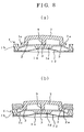
- Fig. 8(a) is a cross-sectional schematic view of another embodiment of the present invention.
- Fig. 8(b) is a cross-sectional schematic view of another embodiment of the present invention.
- Fig. 9(a) is a cross-sectional schematic view of another embodiment of the present invention.
- Fig. 9(b) is a cross-sectional schematic view of another embodiment of the present invention.
- Fig. 10 is a cross-sectional schematic view of another embodiment of the present invention.
- a light-permeable key pad 1 has an operating portion 1a and a non-operating portion 1b connected to the operating portion 1a formed as an integral body from transparent silicon rubber, other transparent rubber or transparent thermoplastic elastomer such as vinyl chloride based elastomer, polyolefin base elastomer, polysterene-polybutadiene copolymer thermoplastic elastomer, ethylene vinyl acetate elastomer, chlorinated polyethylene elastomer, polyurethane rubber or the like.
- transparent silicon rubber other transparent rubber or transparent thermoplastic elastomer
- vinyl chloride based elastomer polyolefin base elastomer
- polysterene-polybutadiene copolymer thermoplastic elastomer ethylene vinyl acetate elastomer
- chlorinated polyethylene elastomer polyurethane rubber or the like.
- the operating portion 1a is formed from a thin skirt portion 1c, which rises up along a slant from the upper portion of the side surface of the non-operating portion 1b, and a key top support portion 1d which is integrally supported at the upper portion of the skirt portion 1c
- the operating portion 1a in which forms the erect thin skirt portion 1b toward the upper slanting portion thereof, or, as shown in Fig. 2, the slanting skirt portion is eliminated and the key top supporting portion 1d extends out horizontally from a thick side surface of the non-operating portion 1b.
- the operating portion 1a is arranged above a substrate (not shown in the drawings) at a position corresponding to a fixed contact point on the substrate, with a rubber click structure being created by forming an electrically conductive contact member on the underside of the operating portion 1a, or with a dome click structure being created by means of a dome switch such as a metal dome switch (not shown in the drawings).
- the key top 2 made from a thermoplastic resin such as ABS, polycarbonate, acrylic resin or the like, is fixedly mounted to the top of the key top support portion 1d by means of a transparent adhesive 3.
- the upper surface of the key top 2 may have any of a variety of shapes, such as a curved shape which slants in one direction, for example.
- the lower portion of the key top 2 may be formed to include a brim portion 2a, as shown in Fig. 3, or the lower portion of the key top 2 may be formed without such a brim portion.
- a transparent or translucent material around lmm thick e.g., in the range 0.8mm - 1.5mm
- a white-colored material which allows light at a certain intensity to pass therethrough.
- the key top 2 is formed from such partially light -permeable white-colored material, there is no need to form the partial transmission light reflecting membrane 4a described below.
- the transparent adhesive 3 is an adhesive used to bond the key top 2, made of a thermoplastic resin such as ABS, polycarbonate, acrylic resin or the like, with the key pad 1, made of a silicon rubber or other rubber material or thermoplastic elastomer, which is an integral body formed from the operating portion 1a and the non-operating portion 1b.
- the adhesive 3 may be any adhesive which makes it possible to bind two different materials together; for example, it is possible to use a silicon type transparent adhesive in the case of silicon rubber.
- a printed pattern (character) layer 4 is formed in the surface of the key top.
- a partial transmission light reflecting membrane 4a having a bright color to reflect white light and the like is formed on all surfaces the light permeable resin key top 2 except for the underside surface thereof.
- a white coating for example, it is possible to use a white coating as the partial transmission light reflecting membrane.
- a solid chromatic color printing is carried out in red, blue, yellow or the like to form a pattern comprised of a letters, symbols, figures or the like, with all of the solid printing 4b except for the portion containing the pattern being covered by a black opaque membrane 4c.
- Forming of patterrn (character or the like) may be formed using laser or the like.
- the opaque membrane 4c and the portion of the solid printing 4b which contains the pattern (character or the like) is covered by a transparent protective membrane 5 formed from a transparent resin such as urethane or the like.
- the printed pattern layer 4 may be formed to have either a positive condition, in which only the etched character (pattern) portion is printed in a chromatic color, or a negative condition in which all of the printed pattern layer 4 except for the etched character (pattern) is colored.
- the body of the resin key top 2 is formed to have a thickness around 1mm, it is possible to use the above method to form a printed pattern (character) layer 4 without having to apply a white-colored coating to the surface of the key top 2 so long as it is possible for the body of the key top 2 to reflect white light and the like and at the same time allow light at a certain intensity to pass therethrough.
- the underside surface of the key top 2 is fixed to the upper surface of a key operating portion 1a of a key pad 1 by means of the transparent adhesive 3.
- an operating shaft 9 is integrally formed at a central portion of the underside of the transparent keytop 2 which is mounted and bonded to the top of the transparent rubber or thermoplastic elastomer key operating portion 1b. Further, a cavity 10 for making a thin keytop 2 is carved out to form a circular space to receive the operating shaft 9 of the underside of the keytop 2. Further, the thickness of the underside of the keytop 2 should have roughly the same thickness structure. The material used for the keytop 2 should be chosen so as to prevent the keytop 2 from being indented when the keytop 2 is struck by a finger. Of course, the contact surfaces of the keytop 2 and the key operating portion 1a are fixed by means of a transparent adhesive.
- the transparent resin keytop 2 shown in Fig. 9 should preferably be formed from a hard foaming resin such as polyurethane foam or the like.
- the lower portion of the operating shaft 9 of the transparent resin keytop 2 is fitted into the concave portion 1g formed in the central upper portion of the transparent rubber or thermoplastic elastomer key operating portion 1a.
- a vertical bonding is carried out on the fitting portion 11 of the lower portion of the operating shaft 9 fitted into the concave portion 1g, it is possible to achieve an increase in bonding strength several times higher compared to horizontal bonding.
- a protruding portion 1e as shown in Fig. 10 is formed on a central portion of the upper surface of the transparent rubber or thermoplastic elastomer key operating portion 1b, and an insertion hole 1f is formed in the central portion of the protruding portion 1e into which the operating shaft 9 of the trasparent resin keytop 2 fitted and vertically bonded by the application of a transparent adhesive.
- the number 12 indicates a PET or a metal dome switch.
- the illumination key according to the present invention makes it possible to reliable recognize the character (pattern) on the key top 2 even when the upper surface of the key top 2 has a curved or slanting shape, as the character (pattern) is formed on upper surface of the key top. Furthermore, because the key operating portion creates a rubber-like click sensitivity and a rubber-like elasticity while the resin of the key top portion is made rigid, and because it is possible to reliably achieve a strong bond between the key operating portion and the key top, the illumination key according to the present invention makes it possible to reliably carry out key operations by preventing misoperations and other problems such as peeling or the like.
- the structure described above makes the illumination key according to the present invention suitable for use in thin-type devices such as cellular phones and the like.
- the thin resin key top with partially light-permeable white-colored material, it is not necessary to form a partial transmission type light reflection membrane on the surface of the key top, and also it is easier to recognize the pattern as the key top itself diffuse light uniformly.
- the lower portion of the operating shaft of the keytop is fitted into the concave portion formed in the central portion of the upper surface of the key operating portion when the contact surfaces of the keytop and key operating portion are bonded together, it is possible to carry out a vertical bonding, and this makes it possible to improve the bonding strength by several times in addition to that achieved by horizontal bonding, whereby it becomes possible to increase the bonding strength for a small amount of contact surface. Furthermore, by forming a protruding portion on the central portion of the upper surface of the key operating portion, and by fitting and bonding the operating shaft of the keytop into the insertion hole of such protruding portion, it is possible to achieve an even higher effective bonding .
- an operating shaft at the central portion of the underside of the keytop and a cavity around the periphery of such operating shaft, it becomes possible to make a thin keytop, whereby it becomes possible to reduce the entire weight of the key. Furthermore, by forming the keytop from a hard foaming resin, it is possible to achieve an even higher reduction in weight while preventing the keytop from being indented when struck.
Landscapes
- Push-Button Switches (AREA)
- Manufacture Of Switches (AREA)
- Switch Cases, Indication, And Locking (AREA)
- Injection Moulding Of Plastics Or The Like (AREA)
- Switches With Compound Operations (AREA)
Priority Applications (1)
| Application Number | Priority Date | Filing Date | Title |
|---|---|---|---|
| EP03003191A EP1316979B1 (de) | 1997-02-18 | 1998-01-20 | Beleuchtete Taste |
Applications Claiming Priority (5)
| Application Number | Priority Date | Filing Date | Title |
|---|---|---|---|
| JP4857397 | 1997-02-18 | ||
| JP4857397 | 1997-02-18 | ||
| JP27932197 | 1997-09-29 | ||
| JP9279321A JP2893445B2 (ja) | 1997-02-18 | 1997-09-29 | 照光式キー及びその製造方法 |
| EP98100887A EP0859388B1 (de) | 1997-02-18 | 1998-01-20 | Beleuchtete Taste und Verfahren zu ihrer Herstellung |
Related Parent Applications (1)
| Application Number | Title | Priority Date | Filing Date |
|---|---|---|---|
| EP98100887A Division EP0859388B1 (de) | 1997-02-18 | 1998-01-20 | Beleuchtete Taste und Verfahren zu ihrer Herstellung |
Related Child Applications (1)
| Application Number | Title | Priority Date | Filing Date |
|---|---|---|---|
| EP03003191A Division EP1316979B1 (de) | 1997-02-18 | 1998-01-20 | Beleuchtete Taste |
Publications (2)
| Publication Number | Publication Date |
|---|---|
| EP0939414A1 true EP0939414A1 (de) | 1999-09-01 |
| EP0939414B1 EP0939414B1 (de) | 2003-06-11 |
Family
ID=26388864
Family Applications (3)
| Application Number | Title | Priority Date | Filing Date |
|---|---|---|---|
| EP98100887A Expired - Lifetime EP0859388B1 (de) | 1997-02-18 | 1998-01-20 | Beleuchtete Taste und Verfahren zu ihrer Herstellung |
| EP03003191A Expired - Lifetime EP1316979B1 (de) | 1997-02-18 | 1998-01-20 | Beleuchtete Taste |
| EP99110963A Expired - Lifetime EP0939414B1 (de) | 1997-02-18 | 1998-01-20 | Beleuchtete Taste und Verfahren zu ihrer Herstellung |
Family Applications Before (2)
| Application Number | Title | Priority Date | Filing Date |
|---|---|---|---|
| EP98100887A Expired - Lifetime EP0859388B1 (de) | 1997-02-18 | 1998-01-20 | Beleuchtete Taste und Verfahren zu ihrer Herstellung |
| EP03003191A Expired - Lifetime EP1316979B1 (de) | 1997-02-18 | 1998-01-20 | Beleuchtete Taste |
Country Status (5)
| Country | Link |
|---|---|
| US (1) | US6084190A (de) |
| EP (3) | EP0859388B1 (de) |
| JP (2) | JP2893445B2 (de) |
| CN (1) | CN1295916C (de) |
| DE (4) | DE1316979T1 (de) |
Cited By (3)
| Publication number | Priority date | Publication date | Assignee | Title |
|---|---|---|---|---|
| EP1389790A1 (de) * | 2002-08-12 | 2004-02-18 | Nec Corporation | Beleuchtungseinrichtung für einen Tastschalter und elektronisches Gerät mit solcher Beleuchtungseinrichtung |
| DE102004021542B4 (de) * | 2003-05-08 | 2006-07-13 | Lear Corp., Southfield | Modulares Schaltsystem |
| CN102357966A (zh) * | 2011-07-12 | 2012-02-22 | 东莞市晋源祥塑胶五金电子有限公司 | 硅胶表面贴合tpu的方法 |
Families Citing this family (60)
| Publication number | Priority date | Publication date | Assignee | Title |
|---|---|---|---|---|
| US6677545B2 (en) * | 1997-02-18 | 2004-01-13 | Sunarrow Co., Ltd. | Illumination key and method of manufacture |
| JP3034834B2 (ja) * | 1997-11-11 | 2000-04-17 | ポリマテック株式会社 | 硬質樹脂キートップ付キーパッド |
| GB2345193B (en) * | 1998-12-22 | 2002-07-24 | Nokia Mobile Phones Ltd | Metallic keys |
| TW498710B (en) * | 1999-01-22 | 2002-08-11 | Taisei Plas Co Ltd | Control panel for electronic equipment and method of producing the same |
| JP2000215754A (ja) * | 1999-01-26 | 2000-08-04 | Nec Shizuoka Ltd | 電子機器の操作ボタン構造 |
| EP1132931A4 (de) * | 1999-08-27 | 2004-12-15 | Mitsubishi Electric Corp | Tastschalter und herstellungsverfahren. |
| CN1197105C (zh) * | 1999-08-27 | 2005-04-13 | 三菱电机株式会社 | 按钮开关及开关装置 |
| US10013075B2 (en) | 1999-09-15 | 2018-07-03 | Michael Shipman | Illuminated keyboard |
| US20090201179A1 (en) | 1999-09-15 | 2009-08-13 | Michael Shipman | Illuminated keyboard |
| JP3810237B2 (ja) * | 1999-11-19 | 2006-08-16 | 信越ポリマー株式会社 | 押釦スイッチ用キートップ部材の製造方法 |
| WO2001060028A2 (en) * | 2000-02-14 | 2001-08-16 | Byung Kwan Min | Keypad including polyurethane resin, and apparatus and method for fabricating the same |
| US6259044B1 (en) * | 2000-03-03 | 2001-07-10 | Intermec Ip Corporation | Electronic device with tactile keypad-overlay |
| JP4414066B2 (ja) * | 2000-06-15 | 2010-02-10 | ポリマテック株式会社 | 積層キーシート |
| FI108682B (fi) * | 2000-06-30 | 2002-02-28 | Nokia Corp | Menetelmä elektroniikkalaitteen näppäimistön valmistuksessa |
| JP4499904B2 (ja) * | 2000-11-13 | 2010-07-14 | ポリマテック株式会社 | キースイッチ |
| JP4539943B2 (ja) * | 2000-12-27 | 2010-09-08 | ポリマテック株式会社 | シート状キートップ及びその製造方法 |
| JP2002216568A (ja) * | 2001-01-18 | 2002-08-02 | Polymatech Co Ltd | キーシート |
| US6774330B2 (en) * | 2001-03-27 | 2004-08-10 | Trw Inc. | Multi-stage push button switch apparatus |
| KR20020088178A (ko) * | 2001-05-18 | 2002-11-27 | 주식회사 유일전자 | 필름삽입형 키와 실리콘 고무 조합형 휴대폰용 키패드 및그 제조방법 |
| US6498311B1 (en) | 2001-06-29 | 2002-12-24 | Microsoft Corporation | Multi-layer keys with translucent outer layer |
| JP2003178639A (ja) * | 2001-12-12 | 2003-06-27 | Sunarrow Ltd | ハードベース・キーユニット |
| US6755582B2 (en) * | 2002-04-25 | 2004-06-29 | Hwa-Twu Won | Key structure |
| KR100457800B1 (ko) * | 2002-06-10 | 2004-12-03 | 김욱한 | 핸드폰 키패드 및 이 핸드폰 키패드를 생산하기 위한 이중사출성형금형 |
| EP1376166B1 (de) * | 2002-06-19 | 2011-05-25 | Kabushiki Kaisha Tokai-Rika-Denki-Seisakusho | Folienschaltervorrichtung |
| JP2004087203A (ja) * | 2002-08-23 | 2004-03-18 | Sanyo Electric Co Ltd | キー入力装置及びこれを具えた携帯電話機 |
| US7512229B2 (en) | 2002-10-23 | 2009-03-31 | Sunarrow Ltd | Key unit, method for marking key top, and method for manufacturing key unit using the same |
| JP2004193047A (ja) * | 2002-12-13 | 2004-07-08 | Matsushita Electric Ind Co Ltd | 押圧用突起付可動接点体 |
| US20050149860A1 (en) * | 2002-12-27 | 2005-07-07 | Casio Computer Co., Ltd. | Electronic device manufacture support apparatus, manufacture client terminal device, and recording medium |
| US7616224B2 (en) * | 2003-01-30 | 2009-11-10 | Sunarrow Limited | Process of producing key units wherein marking on their tops made of light-transmitting material can be completed later on |
| JP2005100674A (ja) * | 2003-09-22 | 2005-04-14 | Matsushita Electric Ind Co Ltd | 可動接点体及びこれを用いたリモコン送信機 |
| US20070295588A1 (en) * | 2004-08-25 | 2007-12-27 | Yoshitaka Kamata | Half-Mirror-Ornamented Key Sheet and Keytops |
| TWI243391B (en) * | 2004-09-20 | 2005-11-11 | Asustek Comp Inc | Key and keyboard with efficiency of depth and scattered light |
| US11216078B2 (en) | 2005-01-18 | 2022-01-04 | Michael Shipman | Illuminated keyboard |
| WO2006104291A1 (en) * | 2005-03-29 | 2006-10-05 | Samyoung Technologies Co., Ltd. | Production method of one body style metal touch pad having luminescent pigment and metal keypad having one body style metal touch pad produced by that method |
| ATE498192T1 (de) * | 2005-04-14 | 2011-02-15 | Kostal Leopold Gmbh & Co Kg | Tastenanordnung für ein elektrisches oder elektronisches gerät in einem kraftfahrzeug |
| US20080191904A1 (en) * | 2007-02-12 | 2008-08-14 | Kai-Jie Tsao | Method For Manufacturing Thin Keypad Assembly And Such Assembly |
| TWM320122U (en) * | 2007-02-16 | 2007-10-01 | Inventec Appliances Corp | Ultra-thin keypad and portable electronic apparatus |
| CN101877285B (zh) * | 2009-04-30 | 2012-11-21 | 深圳富泰宏精密工业有限公司 | 按键及设有该按键的电子装置 |
| US20100300857A1 (en) * | 2009-05-27 | 2010-12-02 | Cheng Chia-Fa | Key switch |
| US9012795B2 (en) * | 2010-02-24 | 2015-04-21 | Apple Inc. | Stacked metal and elastomeric dome for key switch |
| TW201131602A (en) * | 2010-03-15 | 2011-09-16 | Ichia Tech Inc | Manufacturing method of keyboard keycap structure |
| US20120171414A1 (en) * | 2011-01-04 | 2012-07-05 | Nokia Corporation | Apparatus and Method for a User Input Element in an Electronic Device |
| US8921720B2 (en) | 2011-04-25 | 2014-12-30 | Blackberry Limited | Apparatus and method pertaining to a key assembly having a plinth-receiving key mat |
| EP2521153B1 (de) * | 2011-04-26 | 2017-03-22 | BlackBerry Limited | Vorrichtung und Verfahren für eine Tastenanordnung mit einer Zapfen aufnehmenden Matte |
| US9844898B2 (en) * | 2011-09-30 | 2017-12-19 | Apple Inc. | Mirror feature in devices |
| US8647203B2 (en) * | 2011-11-04 | 2014-02-11 | Target Brands, Inc. | Transaction product with selectively illuminated buttons |
| KR20140139648A (ko) * | 2013-05-27 | 2014-12-08 | 삼성전자주식회사 | 보호 커버 |
| AU2014278451B2 (en) | 2013-06-09 | 2017-05-18 | Apple Inc. | Laser-formed features |
| JP6225360B2 (ja) * | 2013-08-22 | 2017-11-08 | 日本精機株式会社 | スイッチ操作装置 |
| US9790126B2 (en) | 2013-09-05 | 2017-10-17 | Apple Inc. | Opaque color stack for electronic device |
| US9629271B1 (en) | 2013-09-30 | 2017-04-18 | Apple Inc. | Laser texturing of a surface |
| JP6224649B2 (ja) * | 2015-05-13 | 2017-11-01 | ファナック株式会社 | キースイッチの構造 |
| CN108349296B (zh) | 2016-09-06 | 2019-11-05 | 苹果公司 | 阳极化表面的激光漂白标记 |
| US10075787B1 (en) * | 2017-07-10 | 2018-09-11 | Bose Corporation | Portable loudspeaker |
| CN107481882B (zh) * | 2017-08-15 | 2019-06-04 | 苏州达方电子有限公司 | 具有编码图案的按键结构 |
| US10919326B2 (en) | 2018-07-03 | 2021-02-16 | Apple Inc. | Controlled ablation and surface modification for marking an electronic device |
| US11200386B2 (en) | 2018-09-27 | 2021-12-14 | Apple Inc. | Electronic card having an electronic interface |
| US11571766B2 (en) | 2018-12-10 | 2023-02-07 | Apple Inc. | Laser marking of an electronic device through a cover |
| JPWO2020213049A1 (de) * | 2019-04-16 | 2020-10-22 | ||
| US11299421B2 (en) | 2019-05-13 | 2022-04-12 | Apple Inc. | Electronic device enclosure with a glass member having an internal encoded marking |
Citations (7)
| Publication number | Priority date | Publication date | Assignee | Title |
|---|---|---|---|---|
| US3978297A (en) * | 1975-03-31 | 1976-08-31 | Chomerics, Inc. | Keyboard switch assembly with improved pushbutton and associated double snap acting actuator/contactor structure |
| US4937408A (en) * | 1988-05-30 | 1990-06-26 | Mitsubishi Denki Kabushiki Kaisha | Self-illuminating panel switch |
| US5138119A (en) * | 1991-03-15 | 1992-08-11 | Lucas Duralith Corporation | Backlit tactile keyboard with improved tactile and electrical characteristics |
| EP0554084A2 (de) * | 1992-01-28 | 1993-08-04 | Nec Corporation | Anordnung von einer beleuchteten Drucktaste |
| EP0593804A1 (de) * | 1991-09-20 | 1994-04-27 | Sunarrow Co., Ltd. | Beleuchteter Drucktastenschalter |
| US5399821A (en) * | 1993-10-20 | 1995-03-21 | Teikoku Tsushin Kogyo Co., Ltd. | Keytop for push-button switches, and method of manufacturing same |
| GB2288911A (en) * | 1994-04-19 | 1995-11-01 | Silitek Corp | Key switch |
Family Cites Families (4)
| Publication number | Priority date | Publication date | Assignee | Title |
|---|---|---|---|---|
| JPH0233816A (ja) * | 1988-07-21 | 1990-02-05 | Alps Electric Co Ltd | キートップ |
| US5036440A (en) * | 1989-05-23 | 1991-07-30 | Alps Electric Co., Ltd. | Illumination type keytop |
| US5475192A (en) * | 1993-03-15 | 1995-12-12 | Teikoku Tsushin Kogyo Co., Ltd. | Keytop sheet for push-button switches |
| US5510584A (en) * | 1995-03-07 | 1996-04-23 | Itt Corporation | Sequentially operated snap action membrane switches |
-
1997
- 1997-09-29 JP JP9279321A patent/JP2893445B2/ja not_active Expired - Fee Related
-
1998
- 1998-01-14 US US09/006,763 patent/US6084190A/en not_active Expired - Lifetime
- 1998-01-20 EP EP98100887A patent/EP0859388B1/de not_active Expired - Lifetime
- 1998-01-20 DE DE1316979T patent/DE1316979T1/de active Pending
- 1998-01-20 DE DE69824980T patent/DE69824980T2/de not_active Expired - Fee Related
- 1998-01-20 EP EP03003191A patent/EP1316979B1/de not_active Expired - Lifetime
- 1998-01-20 EP EP99110963A patent/EP0939414B1/de not_active Expired - Lifetime
- 1998-01-20 DE DE69815493T patent/DE69815493T2/de not_active Expired - Lifetime
- 1998-01-20 DE DE69805127T patent/DE69805127T2/de not_active Expired - Lifetime
- 1998-02-17 CN CNB981038867A patent/CN1295916C/zh not_active Expired - Fee Related
- 1998-07-31 JP JP10229516A patent/JPH11167835A/ja active Pending
Patent Citations (7)
| Publication number | Priority date | Publication date | Assignee | Title |
|---|---|---|---|---|
| US3978297A (en) * | 1975-03-31 | 1976-08-31 | Chomerics, Inc. | Keyboard switch assembly with improved pushbutton and associated double snap acting actuator/contactor structure |
| US4937408A (en) * | 1988-05-30 | 1990-06-26 | Mitsubishi Denki Kabushiki Kaisha | Self-illuminating panel switch |
| US5138119A (en) * | 1991-03-15 | 1992-08-11 | Lucas Duralith Corporation | Backlit tactile keyboard with improved tactile and electrical characteristics |
| EP0593804A1 (de) * | 1991-09-20 | 1994-04-27 | Sunarrow Co., Ltd. | Beleuchteter Drucktastenschalter |
| EP0554084A2 (de) * | 1992-01-28 | 1993-08-04 | Nec Corporation | Anordnung von einer beleuchteten Drucktaste |
| US5399821A (en) * | 1993-10-20 | 1995-03-21 | Teikoku Tsushin Kogyo Co., Ltd. | Keytop for push-button switches, and method of manufacturing same |
| GB2288911A (en) * | 1994-04-19 | 1995-11-01 | Silitek Corp | Key switch |
Cited By (4)
| Publication number | Priority date | Publication date | Assignee | Title |
|---|---|---|---|---|
| EP1389790A1 (de) * | 2002-08-12 | 2004-02-18 | Nec Corporation | Beleuchtungseinrichtung für einen Tastschalter und elektronisches Gerät mit solcher Beleuchtungseinrichtung |
| US6997572B2 (en) | 2002-08-12 | 2006-02-14 | Nec Corporation | Illumination structure for pushbutton and electronic device with pushbutton having illumination structure |
| DE102004021542B4 (de) * | 2003-05-08 | 2006-07-13 | Lear Corp., Southfield | Modulares Schaltsystem |
| CN102357966A (zh) * | 2011-07-12 | 2012-02-22 | 东莞市晋源祥塑胶五金电子有限公司 | 硅胶表面贴合tpu的方法 |
Also Published As
| Publication number | Publication date |
|---|---|
| CN1295916C (zh) | 2007-01-17 |
| EP1316979B1 (de) | 2004-07-07 |
| DE1316979T1 (de) | 2003-11-27 |
| EP0859388B1 (de) | 2002-05-02 |
| EP0939414B1 (de) | 2003-06-11 |
| DE69824980T2 (de) | 2005-07-07 |
| JP2893445B2 (ja) | 1999-05-24 |
| DE69815493T2 (de) | 2004-05-19 |
| DE69805127D1 (de) | 2002-06-06 |
| EP0859388A3 (de) | 1998-08-26 |
| DE69815493D1 (de) | 2003-07-17 |
| EP0859388A2 (de) | 1998-08-19 |
| JPH11167835A (ja) | 1999-06-22 |
| JPH10294037A (ja) | 1998-11-04 |
| DE69805127T2 (de) | 2002-11-28 |
| US6084190A (en) | 2000-07-04 |
| CN1199974A (zh) | 1998-11-25 |
| DE69824980D1 (de) | 2004-08-12 |
| EP1316979A1 (de) | 2003-06-04 |
Similar Documents
| Publication | Publication Date | Title |
|---|---|---|
| EP0939414B1 (de) | Beleuchtete Taste und Verfahren zu ihrer Herstellung | |
| US6677545B2 (en) | Illumination key and method of manufacture | |
| EP0593804B1 (de) | Beleuchteter Drucktastenschalter | |
| KR100464975B1 (ko) | 이동통신단말기용 키스위치 패드 및 메탈돔 시트 | |
| EP1739934B1 (de) | Tastaturblock für ein tragbares Endgerät | |
| KR101228452B1 (ko) | 키패드 어셈블리 및 이를 구비한 휴대 단말기 | |
| US7952043B2 (en) | Keyboard with backlighting functionality | |
| US7186935B2 (en) | Keypad assembly for a portable terminal | |
| US8362928B2 (en) | Keypad assembly | |
| JPH04354232A (ja) | 電話機 | |
| US7655878B2 (en) | Key sheet and key sheet manufacturing method | |
| US20100148994A1 (en) | Keyboard with Backlighting Functionality | |
| US20070013664A1 (en) | Keypad, keypad assembly and portable terminal | |
| JPH06275169A (ja) | キーボードスイッチ | |
| US7946720B2 (en) | Light guide sheet, movable contact structure using the light guide sheet, method of manufacturing the movable contact structure, and switch using the light guide sheet and the movable contact structure | |
| JP5239355B2 (ja) | 可動接点体の製造方法 | |
| FI118446B (fi) | Valaiseva näppäin ja menetelmä sen valmistamiseksi | |
| JPH1127362A (ja) | 照光式キー及びその製造方法 | |
| JPH0758815A (ja) | 携帯電話器の操作装置 | |
| JP3293077B2 (ja) | フレキシブル照光式キー | |
| JP2004095252A (ja) | 押ボタンスイッチ構造体及びこれを備えた携帯型電子機器 | |
| JP2000357429A (ja) | 携帯電話用操作スイッチ | |
| JPH11167838A (ja) | 照光式キースイッチ | |
| HK1015993A (en) | Illumination key and method of manufacture thereof | |
| JPH05260146A (ja) | 電話機のキートップ照明構造 |
Legal Events
| Date | Code | Title | Description |
|---|---|---|---|
| PUAI | Public reference made under article 153(3) epc to a published international application that has entered the european phase |
Free format text: ORIGINAL CODE: 0009012 |
|
| 17P | Request for examination filed |
Effective date: 19990608 |
|
| AC | Divisional application: reference to earlier application |
Ref document number: 859388 Country of ref document: EP |
|
| AK | Designated contracting states |
Kind code of ref document: A1 Designated state(s): DE FR GB IT NL SE |
|
| 17Q | First examination report despatched |
Effective date: 20020409 |
|
| GRAH | Despatch of communication of intention to grant a patent |
Free format text: ORIGINAL CODE: EPIDOS IGRA |
|
| GRAH | Despatch of communication of intention to grant a patent |
Free format text: ORIGINAL CODE: EPIDOS IGRA |
|
| GRAA | (expected) grant |
Free format text: ORIGINAL CODE: 0009210 |
|
| RAP1 | Party data changed (applicant data changed or rights of an application transferred) |
Owner name: SUNARROW LTD. |
|
| AC | Divisional application: reference to earlier application |
Ref document number: 0859388 Country of ref document: EP Kind code of ref document: P |
|
| AK | Designated contracting states |
Designated state(s): DE FR GB IT NL SE |
|
| REG | Reference to a national code |
Ref country code: GB Ref legal event code: FG4D |
|
| REF | Corresponds to: |
Ref document number: 69815493 Country of ref document: DE Date of ref document: 20030717 Kind code of ref document: P |
|
| REG | Reference to a national code |
Ref country code: SE Ref legal event code: TRGR |
|
| ET | Fr: translation filed | ||
| PLBE | No opposition filed within time limit |
Free format text: ORIGINAL CODE: 0009261 |
|
| STAA | Information on the status of an ep patent application or granted ep patent |
Free format text: STATUS: NO OPPOSITION FILED WITHIN TIME LIMIT |
|
| 26N | No opposition filed |
Effective date: 20040312 |
|
| PGFP | Annual fee paid to national office [announced via postgrant information from national office to epo] |
Ref country code: NL Payment date: 20060103 Year of fee payment: 9 |
|
| PGFP | Annual fee paid to national office [announced via postgrant information from national office to epo] |
Ref country code: FR Payment date: 20060110 Year of fee payment: 9 |
|
| PGFP | Annual fee paid to national office [announced via postgrant information from national office to epo] |
Ref country code: IT Payment date: 20060131 Year of fee payment: 9 |
|
| NLV4 | Nl: lapsed or anulled due to non-payment of the annual fee |
Effective date: 20070801 |
|
| REG | Reference to a national code |
Ref country code: FR Ref legal event code: ST Effective date: 20070930 |
|
| PG25 | Lapsed in a contracting state [announced via postgrant information from national office to epo] |
Ref country code: NL Free format text: LAPSE BECAUSE OF NON-PAYMENT OF DUE FEES Effective date: 20070801 |
|
| PG25 | Lapsed in a contracting state [announced via postgrant information from national office to epo] |
Ref country code: FR Free format text: LAPSE BECAUSE OF NON-PAYMENT OF DUE FEES Effective date: 20070131 |
|
| PG25 | Lapsed in a contracting state [announced via postgrant information from national office to epo] |
Ref country code: IT Free format text: LAPSE BECAUSE OF NON-PAYMENT OF DUE FEES Effective date: 20070120 |
|
| PGFP | Annual fee paid to national office [announced via postgrant information from national office to epo] |
Ref country code: DE Payment date: 20100315 Year of fee payment: 13 |
|
| PGFP | Annual fee paid to national office [announced via postgrant information from national office to epo] |
Ref country code: SE Payment date: 20110113 Year of fee payment: 14 |
|
| PGFP | Annual fee paid to national office [announced via postgrant information from national office to epo] |
Ref country code: GB Payment date: 20110119 Year of fee payment: 14 |
|
| REG | Reference to a national code |
Ref country code: DE Ref legal event code: R119 Ref document number: 69815493 Country of ref document: DE Effective date: 20110802 |
|
| REG | Reference to a national code |
Ref country code: SE Ref legal event code: EUG |
|
| GBPC | Gb: european patent ceased through non-payment of renewal fee |
Effective date: 20120120 |
|
| PG25 | Lapsed in a contracting state [announced via postgrant information from national office to epo] |
Ref country code: GB Free format text: LAPSE BECAUSE OF NON-PAYMENT OF DUE FEES Effective date: 20120120 Ref country code: SE Free format text: LAPSE BECAUSE OF NON-PAYMENT OF DUE FEES Effective date: 20120121 |
|
| PG25 | Lapsed in a contracting state [announced via postgrant information from national office to epo] |
Ref country code: DE Free format text: LAPSE BECAUSE OF NON-PAYMENT OF DUE FEES Effective date: 20110802 |