EP0939729B1 - Dispositif de scellage pour emballages a remplissage aseptique dans des conditions steriles - Google Patents
Dispositif de scellage pour emballages a remplissage aseptique dans des conditions steriles Download PDFInfo
- Publication number
- EP0939729B1 EP0939729B1 EP97912158A EP97912158A EP0939729B1 EP 0939729 B1 EP0939729 B1 EP 0939729B1 EP 97912158 A EP97912158 A EP 97912158A EP 97912158 A EP97912158 A EP 97912158A EP 0939729 B1 EP0939729 B1 EP 0939729B1
- Authority
- EP
- European Patent Office
- Prior art keywords
- sealing
- jaw
- movement
- drive
- sealing jaw
- Prior art date
- Legal status (The legal status is an assumption and is not a legal conclusion. Google has not performed a legal analysis and makes no representation as to the accuracy of the status listed.)
- Expired - Lifetime
Links
- 238000007789 sealing Methods 0.000 title claims abstract description 102
- XLYOFNOQVPJJNP-UHFFFAOYSA-N water Substances O XLYOFNOQVPJJNP-UHFFFAOYSA-N 0.000 claims abstract description 18
- 239000012530 fluid Substances 0.000 claims abstract description 8
- 235000001674 Agaricus brunnescens Nutrition 0.000 claims description 13
- 230000009977 dual effect Effects 0.000 claims 1
- 238000002604 ultrasonography Methods 0.000 claims 1
- 239000011092 plastic-coated paper Substances 0.000 abstract description 3
- 238000004140 cleaning Methods 0.000 description 6
- 238000012423 maintenance Methods 0.000 description 4
- 238000004519 manufacturing process Methods 0.000 description 4
- 238000000034 method Methods 0.000 description 4
- 235000013305 food Nutrition 0.000 description 3
- 239000008223 sterile water Substances 0.000 description 3
- 238000003466 welding Methods 0.000 description 3
- 239000002253 acid Substances 0.000 description 2
- 150000007513 acids Chemical class 0.000 description 2
- 230000008878 coupling Effects 0.000 description 2
- 238000010168 coupling process Methods 0.000 description 2
- 238000005859 coupling reaction Methods 0.000 description 2
- 230000003670 easy-to-clean Effects 0.000 description 2
- 239000010720 hydraulic oil Substances 0.000 description 2
- 239000000314 lubricant Substances 0.000 description 2
- 239000000463 material Substances 0.000 description 2
- 238000005096 rolling process Methods 0.000 description 2
- 230000001954 sterilising effect Effects 0.000 description 2
- 238000012371 Aseptic Filling Methods 0.000 description 1
- 208000035874 Excoriation Diseases 0.000 description 1
- 238000005299 abrasion Methods 0.000 description 1
- 239000004480 active ingredient Substances 0.000 description 1
- 230000006978 adaptation Effects 0.000 description 1
- 238000007792 addition Methods 0.000 description 1
- 238000009455 aseptic packaging Methods 0.000 description 1
- 244000052616 bacterial pathogen Species 0.000 description 1
- 239000000969 carrier Substances 0.000 description 1
- 239000012876 carrier material Substances 0.000 description 1
- 239000013043 chemical agent Substances 0.000 description 1
- 238000010276 construction Methods 0.000 description 1
- 238000011109 contamination Methods 0.000 description 1
- 230000001934 delay Effects 0.000 description 1
- 238000013461 design Methods 0.000 description 1
- 238000006073 displacement reaction Methods 0.000 description 1
- 230000002349 favourable effect Effects 0.000 description 1
- 238000005461 lubrication Methods 0.000 description 1
- 238000004806 packaging method and process Methods 0.000 description 1
- 238000012856 packing Methods 0.000 description 1
- 239000004033 plastic Substances 0.000 description 1
- 239000013641 positive control Substances 0.000 description 1
- 238000003825 pressing Methods 0.000 description 1
- 238000012545 processing Methods 0.000 description 1
- 229910052709 silver Inorganic materials 0.000 description 1
- 239000004332 silver Substances 0.000 description 1
- -1 silver ions Chemical class 0.000 description 1
- 239000007787 solid Substances 0.000 description 1
- 229910001220 stainless steel Inorganic materials 0.000 description 1
- 239000010935 stainless steel Substances 0.000 description 1
- 238000004659 sterilization and disinfection Methods 0.000 description 1
- 239000008399 tap water Substances 0.000 description 1
- 235000020679 tap water Nutrition 0.000 description 1
Images


Classifications
-
- B—PERFORMING OPERATIONS; TRANSPORTING
- B29—WORKING OF PLASTICS; WORKING OF SUBSTANCES IN A PLASTIC STATE IN GENERAL
- B29C—SHAPING OR JOINING OF PLASTICS; SHAPING OF MATERIAL IN A PLASTIC STATE, NOT OTHERWISE PROVIDED FOR; AFTER-TREATMENT OF THE SHAPED PRODUCTS, e.g. REPAIRING
- B29C66/00—General aspects of processes or apparatus for joining preformed parts
- B29C66/80—General aspects of machine operations or constructions and parts thereof
- B29C66/82—Pressure application arrangements, e.g. transmission or actuating mechanisms for joining tools or clamps
- B29C66/824—Actuating mechanisms
- B29C66/8242—Pneumatic or hydraulic drives
-
- B—PERFORMING OPERATIONS; TRANSPORTING
- B29—WORKING OF PLASTICS; WORKING OF SUBSTANCES IN A PLASTIC STATE IN GENERAL
- B29C—SHAPING OR JOINING OF PLASTICS; SHAPING OF MATERIAL IN A PLASTIC STATE, NOT OTHERWISE PROVIDED FOR; AFTER-TREATMENT OF THE SHAPED PRODUCTS, e.g. REPAIRING
- B29C65/00—Joining or sealing of preformed parts, e.g. welding of plastics materials; Apparatus therefor
- B29C65/02—Joining or sealing of preformed parts, e.g. welding of plastics materials; Apparatus therefor by heating, with or without pressure
- B29C65/08—Joining or sealing of preformed parts, e.g. welding of plastics materials; Apparatus therefor by heating, with or without pressure using ultrasonic vibrations
-
- B—PERFORMING OPERATIONS; TRANSPORTING
- B29—WORKING OF PLASTICS; WORKING OF SUBSTANCES IN A PLASTIC STATE IN GENERAL
- B29C—SHAPING OR JOINING OF PLASTICS; SHAPING OF MATERIAL IN A PLASTIC STATE, NOT OTHERWISE PROVIDED FOR; AFTER-TREATMENT OF THE SHAPED PRODUCTS, e.g. REPAIRING
- B29C66/00—General aspects of processes or apparatus for joining preformed parts
- B29C66/01—General aspects dealing with the joint area or with the area to be joined
- B29C66/05—Particular design of joint configurations
- B29C66/10—Particular design of joint configurations particular design of the joint cross-sections
- B29C66/11—Joint cross-sections comprising a single joint-segment, i.e. one of the parts to be joined comprising a single joint-segment in the joint cross-section
- B29C66/112—Single lapped joints
- B29C66/1122—Single lap to lap joints, i.e. overlap joints
-
- B—PERFORMING OPERATIONS; TRANSPORTING
- B29—WORKING OF PLASTICS; WORKING OF SUBSTANCES IN A PLASTIC STATE IN GENERAL
- B29C—SHAPING OR JOINING OF PLASTICS; SHAPING OF MATERIAL IN A PLASTIC STATE, NOT OTHERWISE PROVIDED FOR; AFTER-TREATMENT OF THE SHAPED PRODUCTS, e.g. REPAIRING
- B29C66/00—General aspects of processes or apparatus for joining preformed parts
- B29C66/01—General aspects dealing with the joint area or with the area to be joined
- B29C66/05—Particular design of joint configurations
- B29C66/10—Particular design of joint configurations particular design of the joint cross-sections
- B29C66/13—Single flanged joints; Fin-type joints; Single hem joints; Edge joints; Interpenetrating fingered joints; Other specific particular designs of joint cross-sections not provided for in groups B29C66/11 - B29C66/12
- B29C66/131—Single flanged joints, i.e. one of the parts to be joined being rigid and flanged in the joint area
- B29C66/1312—Single flange to flange joints, the parts to be joined being rigid
-
- B—PERFORMING OPERATIONS; TRANSPORTING
- B29—WORKING OF PLASTICS; WORKING OF SUBSTANCES IN A PLASTIC STATE IN GENERAL
- B29C—SHAPING OR JOINING OF PLASTICS; SHAPING OF MATERIAL IN A PLASTIC STATE, NOT OTHERWISE PROVIDED FOR; AFTER-TREATMENT OF THE SHAPED PRODUCTS, e.g. REPAIRING
- B29C66/00—General aspects of processes or apparatus for joining preformed parts
- B29C66/01—General aspects dealing with the joint area or with the area to be joined
- B29C66/346—Making joints having variable thicknesses in the joint area, e.g. by using jaws having an adapted configuration
-
- B—PERFORMING OPERATIONS; TRANSPORTING
- B29—WORKING OF PLASTICS; WORKING OF SUBSTANCES IN A PLASTIC STATE IN GENERAL
- B29C—SHAPING OR JOINING OF PLASTICS; SHAPING OF MATERIAL IN A PLASTIC STATE, NOT OTHERWISE PROVIDED FOR; AFTER-TREATMENT OF THE SHAPED PRODUCTS, e.g. REPAIRING
- B29C66/00—General aspects of processes or apparatus for joining preformed parts
- B29C66/40—General aspects of joining substantially flat articles, e.g. plates, sheets or web-like materials; Making flat seams in tubular or hollow articles; Joining single elements to substantially flat surfaces
- B29C66/41—Joining substantially flat articles ; Making flat seams in tubular or hollow articles
- B29C66/43—Joining a relatively small portion of the surface of said articles
- B29C66/431—Joining the articles to themselves
- B29C66/4312—Joining the articles to themselves for making flat seams in tubular or hollow articles, e.g. transversal seams
- B29C66/43121—Closing the ends of tubular or hollow single articles, e.g. closing the ends of bags
- B29C66/43122—Closing the top of gable top containers
-
- B—PERFORMING OPERATIONS; TRANSPORTING
- B29—WORKING OF PLASTICS; WORKING OF SUBSTANCES IN A PLASTIC STATE IN GENERAL
- B29C—SHAPING OR JOINING OF PLASTICS; SHAPING OF MATERIAL IN A PLASTIC STATE, NOT OTHERWISE PROVIDED FOR; AFTER-TREATMENT OF THE SHAPED PRODUCTS, e.g. REPAIRING
- B29C66/00—General aspects of processes or apparatus for joining preformed parts
- B29C66/80—General aspects of machine operations or constructions and parts thereof
- B29C66/81—General aspects of the pressing elements, i.e. the elements applying pressure on the parts to be joined in the area to be joined, e.g. the welding jaws or clamps
- B29C66/814—General aspects of the pressing elements, i.e. the elements applying pressure on the parts to be joined in the area to be joined, e.g. the welding jaws or clamps characterised by the design of the pressing elements, e.g. of the welding jaws or clamps
- B29C66/8141—General aspects of the pressing elements, i.e. the elements applying pressure on the parts to be joined in the area to be joined, e.g. the welding jaws or clamps characterised by the design of the pressing elements, e.g. of the welding jaws or clamps characterised by the surface geometry of the part of the pressing elements, e.g. welding jaws or clamps, coming into contact with the parts to be joined
- B29C66/81427—General aspects of the pressing elements, i.e. the elements applying pressure on the parts to be joined in the area to be joined, e.g. the welding jaws or clamps characterised by the design of the pressing elements, e.g. of the welding jaws or clamps characterised by the surface geometry of the part of the pressing elements, e.g. welding jaws or clamps, coming into contact with the parts to be joined comprising a single ridge, e.g. for making a weakening line; comprising a single tooth
-
- B—PERFORMING OPERATIONS; TRANSPORTING
- B29—WORKING OF PLASTICS; WORKING OF SUBSTANCES IN A PLASTIC STATE IN GENERAL
- B29C—SHAPING OR JOINING OF PLASTICS; SHAPING OF MATERIAL IN A PLASTIC STATE, NOT OTHERWISE PROVIDED FOR; AFTER-TREATMENT OF THE SHAPED PRODUCTS, e.g. REPAIRING
- B29C66/00—General aspects of processes or apparatus for joining preformed parts
- B29C66/80—General aspects of machine operations or constructions and parts thereof
- B29C66/83—General aspects of machine operations or constructions and parts thereof characterised by the movement of the joining or pressing tools
- B29C66/832—Reciprocating joining or pressing tools
- B29C66/8322—Joining or pressing tools reciprocating along one axis
-
- B—PERFORMING OPERATIONS; TRANSPORTING
- B29—WORKING OF PLASTICS; WORKING OF SUBSTANCES IN A PLASTIC STATE IN GENERAL
- B29C—SHAPING OR JOINING OF PLASTICS; SHAPING OF MATERIAL IN A PLASTIC STATE, NOT OTHERWISE PROVIDED FOR; AFTER-TREATMENT OF THE SHAPED PRODUCTS, e.g. REPAIRING
- B29C66/00—General aspects of processes or apparatus for joining preformed parts
- B29C66/80—General aspects of machine operations or constructions and parts thereof
- B29C66/87—Auxiliary operations or devices
- B29C66/876—Maintenance or cleaning
-
- B—PERFORMING OPERATIONS; TRANSPORTING
- B29—WORKING OF PLASTICS; WORKING OF SUBSTANCES IN A PLASTIC STATE IN GENERAL
- B29C—SHAPING OR JOINING OF PLASTICS; SHAPING OF MATERIAL IN A PLASTIC STATE, NOT OTHERWISE PROVIDED FOR; AFTER-TREATMENT OF THE SHAPED PRODUCTS, e.g. REPAIRING
- B29C66/00—General aspects of processes or apparatus for joining preformed parts
- B29C66/90—Measuring or controlling the joining process
- B29C66/92—Measuring or controlling the joining process by measuring or controlling the pressure, the force, the mechanical power or the displacement of the joining tools
- B29C66/924—Measuring or controlling the joining process by measuring or controlling the pressure, the force, the mechanical power or the displacement of the joining tools by controlling or regulating the pressure, the force, the mechanical power or the displacement of the joining tools
- B29C66/9241—Measuring or controlling the joining process by measuring or controlling the pressure, the force, the mechanical power or the displacement of the joining tools by controlling or regulating the pressure, the force, the mechanical power or the displacement of the joining tools by controlling or regulating the pressure, the force or the mechanical power
-
- B—PERFORMING OPERATIONS; TRANSPORTING
- B29—WORKING OF PLASTICS; WORKING OF SUBSTANCES IN A PLASTIC STATE IN GENERAL
- B29C—SHAPING OR JOINING OF PLASTICS; SHAPING OF MATERIAL IN A PLASTIC STATE, NOT OTHERWISE PROVIDED FOR; AFTER-TREATMENT OF THE SHAPED PRODUCTS, e.g. REPAIRING
- B29C66/00—General aspects of processes or apparatus for joining preformed parts
- B29C66/90—Measuring or controlling the joining process
- B29C66/92—Measuring or controlling the joining process by measuring or controlling the pressure, the force, the mechanical power or the displacement of the joining tools
- B29C66/924—Measuring or controlling the joining process by measuring or controlling the pressure, the force, the mechanical power or the displacement of the joining tools by controlling or regulating the pressure, the force, the mechanical power or the displacement of the joining tools
- B29C66/9261—Measuring or controlling the joining process by measuring or controlling the pressure, the force, the mechanical power or the displacement of the joining tools by controlling or regulating the pressure, the force, the mechanical power or the displacement of the joining tools by controlling or regulating the displacement of the joining tools
- B29C66/92611—Measuring or controlling the joining process by measuring or controlling the pressure, the force, the mechanical power or the displacement of the joining tools by controlling or regulating the pressure, the force, the mechanical power or the displacement of the joining tools by controlling or regulating the displacement of the joining tools by controlling or regulating the gap between the joining tools
-
- B—PERFORMING OPERATIONS; TRANSPORTING
- B29—WORKING OF PLASTICS; WORKING OF SUBSTANCES IN A PLASTIC STATE IN GENERAL
- B29C—SHAPING OR JOINING OF PLASTICS; SHAPING OF MATERIAL IN A PLASTIC STATE, NOT OTHERWISE PROVIDED FOR; AFTER-TREATMENT OF THE SHAPED PRODUCTS, e.g. REPAIRING
- B29C66/00—General aspects of processes or apparatus for joining preformed parts
- B29C66/90—Measuring or controlling the joining process
- B29C66/92—Measuring or controlling the joining process by measuring or controlling the pressure, the force, the mechanical power or the displacement of the joining tools
- B29C66/924—Measuring or controlling the joining process by measuring or controlling the pressure, the force, the mechanical power or the displacement of the joining tools by controlling or regulating the pressure, the force, the mechanical power or the displacement of the joining tools
- B29C66/9261—Measuring or controlling the joining process by measuring or controlling the pressure, the force, the mechanical power or the displacement of the joining tools by controlling or regulating the pressure, the force, the mechanical power or the displacement of the joining tools by controlling or regulating the displacement of the joining tools
- B29C66/92651—Measuring or controlling the joining process by measuring or controlling the pressure, the force, the mechanical power or the displacement of the joining tools by controlling or regulating the pressure, the force, the mechanical power or the displacement of the joining tools by controlling or regulating the displacement of the joining tools by using stops
-
- B—PERFORMING OPERATIONS; TRANSPORTING
- B65—CONVEYING; PACKING; STORING; HANDLING THIN OR FILAMENTARY MATERIAL
- B65B—MACHINES, APPARATUS OR DEVICES FOR, OR METHODS OF, PACKAGING ARTICLES OR MATERIALS; UNPACKING
- B65B55/00—Preserving, protecting or purifying packages or package contents in association with packaging
- B65B55/02—Sterilising, e.g. of complete packages
-
- B—PERFORMING OPERATIONS; TRANSPORTING
- B65—CONVEYING; PACKING; STORING; HANDLING THIN OR FILAMENTARY MATERIAL
- B65B—MACHINES, APPARATUS OR DEVICES FOR, OR METHODS OF, PACKAGING ARTICLES OR MATERIALS; UNPACKING
- B65B7/00—Closing containers or receptacles after filling
- B65B7/16—Closing semi-rigid or rigid containers or receptacles not deformed by, or not taking-up shape of, contents, e.g. boxes or cartons
- B65B7/18—Closing semi-rigid or rigid containers or receptacles not deformed by, or not taking-up shape of, contents, e.g. boxes or cartons by collapsing mouth portion and subsequently folding-down or securing flaps
-
- B—PERFORMING OPERATIONS; TRANSPORTING
- B29—WORKING OF PLASTICS; WORKING OF SUBSTANCES IN A PLASTIC STATE IN GENERAL
- B29C—SHAPING OR JOINING OF PLASTICS; SHAPING OF MATERIAL IN A PLASTIC STATE, NOT OTHERWISE PROVIDED FOR; AFTER-TREATMENT OF THE SHAPED PRODUCTS, e.g. REPAIRING
- B29C66/00—General aspects of processes or apparatus for joining preformed parts
- B29C66/70—General aspects of processes or apparatus for joining preformed parts characterised by the composition, physical properties or the structure of the material of the parts to be joined; Joining with non-plastics material
- B29C66/72—General aspects of processes or apparatus for joining preformed parts characterised by the composition, physical properties or the structure of the material of the parts to be joined; Joining with non-plastics material characterised by the structure of the material of the parts to be joined
- B29C66/723—General aspects of processes or apparatus for joining preformed parts characterised by the composition, physical properties or the structure of the material of the parts to be joined; Joining with non-plastics material characterised by the structure of the material of the parts to be joined being multi-layered
- B29C66/7232—General aspects of processes or apparatus for joining preformed parts characterised by the composition, physical properties or the structure of the material of the parts to be joined; Joining with non-plastics material characterised by the structure of the material of the parts to be joined being multi-layered comprising a non-plastics layer
- B29C66/72327—General aspects of processes or apparatus for joining preformed parts characterised by the composition, physical properties or the structure of the material of the parts to be joined; Joining with non-plastics material characterised by the structure of the material of the parts to be joined being multi-layered comprising a non-plastics layer consisting of natural products or their composites, not provided for in B29C66/72321 - B29C66/72324
- B29C66/72328—Paper
-
- B—PERFORMING OPERATIONS; TRANSPORTING
- B29—WORKING OF PLASTICS; WORKING OF SUBSTANCES IN A PLASTIC STATE IN GENERAL
- B29C—SHAPING OR JOINING OF PLASTICS; SHAPING OF MATERIAL IN A PLASTIC STATE, NOT OTHERWISE PROVIDED FOR; AFTER-TREATMENT OF THE SHAPED PRODUCTS, e.g. REPAIRING
- B29C66/00—General aspects of processes or apparatus for joining preformed parts
- B29C66/80—General aspects of machine operations or constructions and parts thereof
- B29C66/84—Specific machine types or machines suitable for specific applications
- B29C66/849—Packaging machines
-
- B—PERFORMING OPERATIONS; TRANSPORTING
- B29—WORKING OF PLASTICS; WORKING OF SUBSTANCES IN A PLASTIC STATE IN GENERAL
- B29L—INDEXING SCHEME ASSOCIATED WITH SUBCLASS B29C, RELATING TO PARTICULAR ARTICLES
- B29L2031/00—Other particular articles
- B29L2031/712—Containers; Packaging elements or accessories, Packages
- B29L2031/7162—Boxes, cartons, cases
- B29L2031/7166—Cartons of the fruit juice or milk type, i.e. containers of polygonal cross sections formed by folding blanks into a tubular body with end-closing or contents-supporting elements, e.g. gable type containers
-
- Y—GENERAL TAGGING OF NEW TECHNOLOGICAL DEVELOPMENTS; GENERAL TAGGING OF CROSS-SECTIONAL TECHNOLOGIES SPANNING OVER SEVERAL SECTIONS OF THE IPC; TECHNICAL SUBJECTS COVERED BY FORMER USPC CROSS-REFERENCE ART COLLECTIONS [XRACs] AND DIGESTS
- Y10—TECHNICAL SUBJECTS COVERED BY FORMER USPC
- Y10S—TECHNICAL SUBJECTS COVERED BY FORMER USPC CROSS-REFERENCE ART COLLECTIONS [XRACs] AND DIGESTS
- Y10S53/00—Package making
- Y10S53/02—High frequency electric sealing
Definitions
- the invention relates to a device for sealing the closure seam of a sterile filled Pack made of plastic-coated carrier material, for example paper, under aseptic Conditions in a clean room where a sealing jaw is behind in the direction of movement the latter a drive coupled to it and attached to a holding frame stationary and before the sealing jaw in the direction of movement, a counter jaw firmly on the holding frame is appropriate.
- a sealing jaw is behind in the direction of movement the latter a drive coupled to it and attached to a holding frame stationary and before the sealing jaw in the direction of movement, a counter jaw firmly on the holding frame is appropriate.
- the object of the invention is therefore to create a device of the type mentioned at which, while ensuring high production reliability, drives the sealing device can work under aseptic conditions without a hermetically sealed special housing and the device is easy to maintain.
- this object is achieved in that both the device for final sealing under aseptic conditions with sealing jaws and counter jaws as well as the drive in one Clean room are arranged and the drive has a hydraulic cylinder with sterile water is operated as hydraulic fluid and works double-acting. Cylinder with piston and aseptic Water as hydraulic fluid is known per se for drives. With such facilities but it is never processing in a clean room or sterile room. Already the one at the known hydraulics used materials and the associated lubrication processes do not allow a hydraulic drive in a clean room. The specialist in manufacturing of sterile filled packs knows that the food law at home and abroad the use of hydraulic fluids in addition to a sterile filled packing.
- the sealing device Almost all parts and devices of the sealing device according to the invention have surfaces made of stainless steel, some of which are even electropolished to provide easy-to-clean and rust-free surfaces which could, among other things, come into contact with the goods to be packed.
- the invention proposes the solution of having a hydraulic cylinder for the drive Provide piston rod and operate the drive with aseptic water.
- hydraulic drives which are operated with water, but which is not sterile.
- chemical agents which are inexpensive to buy, the usual water (for example from the tap) be made aseptic.
- the silver ions have as an active ingredient.
- the drive according to the invention with the actuated by aseptic water Hydraulic cylinders can also be arranged in the clean room and thus directly against the sealing jaws Move the counter jaws back and forth so that the sealing process can take place in the clean room.
- the axis with the sealing jaws coupled piston rod lies in the line of movement direction, which is the main line of force from the drive to the sealing jaws to the counter jaws.
- the invention Sealing device not only compact and with great production security design, but the force required for operation is along by the hydraulic cylinder this main line of force on the axis, and all forces act up to the front of the contact surface of the sealing jaw in this axial direction. This means that no diversions are necessary, No forces are lost and there are no undesirable tolerances.
- the Holding devices for the entire movable sealing unit are also not burdened and do not suffer from abrasion.
- the hydraulic cylinder of the drive is over a cam control is firmly connected to the machine drive.
- Main drive shaft on which curves are also attached.
- Valves preferably a positive one and separately a negative
- Valves are controlled by this curve and give corresponding ones Signals to the hydraulic cylinder for moving forward to the front surface of the Seal back or for the movement backwards, in the opposite direction.
- Curve control of the control valves achieves very short control times. If only brief Welding and other movement times are available for the sealing unit very short control times due to the curve control described.
- the movable sealing unit between the drive and the front surface of the Sealing jaw is attached to a holding plate which is substantially parallel to the direction of movement of the sealing jaw is arranged in a translationally movable manner on the holding frame.
- This Attachment is preferably releasable and means that the entire sealing unit, in particular the sealing jaws, with the holding plate detached from the holding frame and removed in one piece can be. This makes the device easy to maintain and easy to clean.
- the sealing jaw is in the direction of movement due to its integral connection with the holding plate of the sealing jaw adjustable, because the whole unit can move in the mentioned direction be moved back and forth translationally, for example by the correct gap size adjust. There are very few steps for adjusting the direction of movement of the Seal baking necessary.
- the movable sealing unit by one essential vertical and arranged transversely to the direction of movement of the sealing jaw pin is pivotable relative to the holding plate.
- the adjustment is also with regard to the parallel position the respective front surface of the sealing jaw on the one hand and the counter jaw on the other hand necessary and easily possible through this measure according to the invention.
- a further advantageous embodiment of the invention is between the piston rod A mushroom head interposed between the drive and the movable sealing unit.
- This allows for adjusting a decoupling of the sealing unit from its drive.
- the shape and application a mushroom head is known per se in other areas.
- the use of the mushroom head at enables one simple, reliable and yet adjustable construction. It can thereby be turned on at any time Axis compensation are created.
- the piston rod of the hydraulic cylinder has an advantage Thread on which the mushroom head is screwed.
- a lock nut can do that Fix selected position. For adjustment when the front surfaces of the jaws are in, for example To be brought to each other, the force for moving the sealing unit in the mentioned movement direction translationally generated by the hydraulic cylinder of the drive.
- the seals in the direction of movement of the sealing jaw extending, opposite edges of the holding plate in cross section V-shaped Guide rails are attached, the V cross section tapers outwards and that of two pairs of rollers with a corresponding V-shape are held on the circumference, and if one Pair of rollers rotatable centrally and the opposite, other pair of rollers are arranged eccentrically rotatable on the holding frame.
- Sealing devices according to the invention are the V-shaped guide rails Surface treated and screwed to the edges of the holding plate. But it is also conceivable that the guide rails are otherwise attached to the holding plate, if necessary, this even in one piece with the holding plate.
- the centrally rotatable arrangement of a pair of rollers relative to the eccentrically rotatable Arrangement of the other pair of rollers on the opposite side of the holding plate allows a further advantage to determine or increase the friction between the Pairs of rollers and the guide rails when tightening and loosening when loosening.
- a simple rotation of the eccentrically mounted roller will make the holding plate stronger against the Rolling pressed resulting in increased friction.
- rotating the respective eccentric roll can be easily achieved a desired bias.
- At least one of the V-shaped guide rails can also be located approximately in the middle Area of their longitudinal extent be interrupted by a recess. In the area of this itself In the rail direction extending recess, so to speak, the V-shaped raised profile is missing Rail.
- the length of the recess is expediently somewhat larger than that Diameter of the roll used in each case.
- the purpose of this measure is easy Removal of the movable sealing unit without, for example, completely removing the rollers have to. You become the two roles of a couple at a distance from each other arrange, which is approximately as large as the longitudinal extent of the holding plate (in the direction of movement of the Sealing jaws).
- the distance between the axis of the one roller and the center of the mentioned recess is then chosen to be as large as the distance along the guide rail that the each other role is removed from the end of the guide rail with the result that when Moving in the roll (relative movement, because it is always the holding plate opposite the fixed roller moves) into the recess then simultaneously the other roller over the end the guide rail runs out, so that finally both rollers of the V-shaped cross section the guide rail are disengaged and the holding plate with the whole arranged thereon (movable) sealing unit can be removed from the rollers.
- the roles are in expediently rotatably attached to the holding frame. Again, the ease of maintenance and easy cleaning of the individual units of the sealing device recognizable according to the invention.
- the sealing jaw is used as an ultrasonic sonotrode is formed, which is fixedly connected to a converter attached to the holding plate, and if the counter jaw is designed as an anvil. So far, ultrasonic sealing has been used only used in the non-aseptic area when closing gable packs.
- the measures and boundary conditions according to the invention can also be a sealing unit Have sonotrode.
- a pneumatic system could be used for a positive control of the sealing unit Use seems impossible due to the conditions of the clean room. Since one for the sealing of the closure seam needs an exact pressure, one needs on the side of the A counter-jaw or the anvil a cushion, a spring element, for example pneumatic pressure pad. But this can only be done pneumatically or hydraulically. Among other things, due to the materials and the leaks, there is no pneumatics Another hydraulic system is used in the clean room. By using aseptic water as Hydraulic fluid can also be arranged in the clean room. There are with Advantage the hot air flows are no longer required for sterilization.
- the surfaces of the Sealing device according to the invention can be sterilized by acids, the acids can be washed off by water, and important germ carriers, such as those in Hot air used in the prior art is required in the clean room of the invention Device no longer to be used.
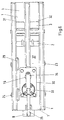
- the stiffening three-rail holding frame 1 holds the entire device and here in particular the sealing jaws designed as an ultrasonic sonotrode and the anvil 3 trained counter jaws.
- a converter 4 is connected to the sonotrode 2.
- the sonotrode 2 with converter 4 is attached under the holding frame 1 via a holding plate 5. Consequently are the sonotrode 2 and the converter 4 in the direction of movement designated 6 movable, which is why this movable unit as a whole as the movable sealing unit 7 is designated.
- the movable sealing unit 7 is not only exclusively along this main force line 15 in Direction of movement 6 translationally back and forth. Rather, there is one Rotational mobility of this sealing unit 7, namely by one, clearly in FIGS. 4 and 6 visible pin 16, the axis of rotation on the main line of force 15 and on a plane perpendicular stands, which lies in the main line of force 15 and in the representation of Figures 4 to 6 Paper plane is. With regard to Figures 2 and 3, this level is in the direction of view and contains again the main line of force 15. So that an adaptation of this also rotatable Sealing unit 7 on the axis of the piston rod 9 of the drive 8 fastened to the holding frame 1 is possible, according to the representation of FIG. 5, the foremost (right in FIG.
- the pin 16 is fastened to the movable sealing unit 7 and projects upwards therefrom Direction towards the holding frame 1 and into a bore 19 in the holding plate 5.
- the Pin 16 ends in this bore 19 in the holding plate 5.
- the sealing unit 7 can thus turn rotate the pin 16 relative to the holding plate 5.
- the holding plate 5 in turn is only relative to Holding frame 1 can be moved translationally in the direction of the double arrow 6.
- Edges 20, 20 'screwed on guide rails 21, 21' Their cross-section is V-shaped, that the outer edges of these guide rails 21, 21 'taper outwards.
- the Guide rails run (as at the bottom of a V at the tip) outwards in the 22, 22 'designated outer edge.
- the ease of maintenance of the entire structure of the sealing device is also in following detail particularly clear.
- the V-shaped edge for guiding the rollers is missing, so to speak 23, 24 with the result that when moving the holding plate 5 in the direction of movement 6 when Example the rollers 23, 24 on the right in FIG. 4 come into this recess 26, the holding plate 5 is then no longer held by these right-hand rollers 23, 24, but rather despite Presence of the rollers 23, 24 can be disengaged from them.
- the distance a between the center of the right front outer edge 22 or 22 'of the guide rail 21 or 21 'and the center of the recess 26 is greater than the distance b between the Axis of the lower left roller 23 (FIG. 4) and the rear end edge 27 of the holding plate 5.
- a displacement of the holding plate 5 for example to the right in the direction of the anvil 3 by the distance a is sufficient to the rear end edge 27 of the Holding plate 5 in front of the respective rear roller of the upper pair of rollers 24 and also the lower one Bring pair of rollers 23, while at the same time the recess 26 in the area of the front Rolling of the two pairs 23, 24 comes to lie with the result that the holding plate can take out without the centrically or eccentrically arranged pairs of rollers 23, 24 to solve. This significantly increases production reliability and also ease of maintenance.
- the holding plate 5 runs load-free between the pairs of rollers 23, 24.
- the sealing unit 7 is moved in the direction of the double arrow to the right towards the anvil 3 (with the help of the drive 8 and its hydraulic cylinder driven with sterile water), and finally, by loosening the coupling between drive 8 and mushroom head 17, a pivoting possibility the sealing unit 7 is created via the pin 16 relative to the holding plate 5 and the sealing unit 7 rotated until the front surface 14 of the sonotrode 2 parallel to the Anvil 3 lies. Then all couplings or screw connections can be tightened again, so that in this adjusted position the sealing unit 7 is firmly attached to the holding plate 5 is attached and this entire unit of holding plate 5 and sealing unit 7 again with the Drive 8 or the piston rod 9 is firmly coupled.
- FIG. 6 also shows the top view of frame 1 box-shaped boundary lines 30, 31 and 32 three cleaning openings.
- the flange is for designated the supply hose 34 for the converter 4.
- Zu-35 and discharge hoses 36 for the hydraulic cylinder of the drive 8 are shown.
- the in Figure 6 with 37 designated area in the frame 1 between the boundary lines 30, 31, 32 of the cleaning openings is an intermediate level that can be seen very well in Figure 1 in perspective.
- the introduction of the feed and push back force on the movable sealing unit 7 along the two directions of movement 6 forward to the anvil 3 and back from this away takes place by means of the water hydraulics mentioned.
- the hydraulic cylinder of the drive 8 is special according to 5 clearly connected to the converter 4, and this runs up the cross-sectionally V-shaped guide rails 21, 21 '.
- the mentioned feed by means of a drive 8 generates the actual welding stroke.
- One can rely on mechanical parts or deflection elements dispense with advantage because the introduction of hydraulic power from the drive 8 along the Main line of force 15 takes place directly in the welding zone.
Landscapes
- Engineering & Computer Science (AREA)
- Mechanical Engineering (AREA)
- Physics & Mathematics (AREA)
- Fluid Mechanics (AREA)
- Package Closures (AREA)
- External Artificial Organs (AREA)
- Closing Of Containers (AREA)
- Packages (AREA)
Claims (9)
- Appareillage pour le scellage du cordon d'obturation (13) d'un emballage (11) rempli dans des conditions stériles, dans lequel un organe d'entraínement (8), situé en arrière d'une mâchoire de scellage (2) dans le sens de déplacement (6) de cette mâchoire, est couplé à cette mâchoire de scellage et est rapporté d'une manière fixe à un cadre (1), comporte une tige de piston (9) couplée à la mâchoire de scellage (2), une contre-mâchoire (3) étant disposée en avant de la mâchoire de scellage (2) dans le sens de déplacement (6), caractérisé en ce que tant l'appareillage destiné au scellage final dans des conditions stériles avec la mâchoire de scellage (2) et la contre-mâchoire (3), que l'organe d'entraínement (8), sont disposés dans une salle blanche, et que l'organe d'entraínement (8) comporte un vérin hydraulique, qui est entraíné par de l'eau stérile servant de liquide hydraulique, et travaille en double effet.
- Appareillage selon la revendication 1, caractérisé en ce que l'axe de la tige de piston (9) se trouve dans la ligne du sens de déplacement (6) qui est la ligne de force principale (15) allant de l'organe d'entraínement (8) à la contre-mâchoire (3) en passant par la mâchoire de scellage (2).
- Appareillage selon la revendication 1 ou 2, caractérisé en ce que le vérin hydraulique de l'organe d'entraínement (8) est relié à demeure à l'organe d'entraínement de la machine par l'intermédiaire d'une commande par came de ses soupapes de commande.
- Appareillage selon l'une des revendications 1 à 3, caractérisé en ce que l'unité de scellage mobile (7) est, entre l'organe d'entraínement (8) et la face frontale (14) de la mâchoire de scellage (2), fixée à une plaque de retenue (5) qui est disposée de façon à pouvoir subir un mouvement de translation, pour l'essentiel parallèle au sens de déplacement (6) de la mâchoire de scellage (2), sur le cadre (1).
- Appareillage selon l'une des revendications 1 à 4, caractérisé en ce que l'unité mobile de scellage (7) peut pivoter par rapport à la plaque de retenue (5) autour d'un pivot (16), essentiellement vertical et disposé transversalement par rapport au sens de déplacement (6) de la mâchoire de scellage (2).
- Appareillage selon l'une des revendications 1 à 5, caractérisé en ce qu'une tête de champignon (17) est intercalée entre la tige de piston (9) de l'organe d'entraínement (8) et l'unité mobile de scellage (7).
- Appareillage selon l'une des revendications 1 à 6, caractérisé en ce que des rails de guidage (21, 21') ayant en section transversale la forme d'un V, sont rapportés aux arêtes opposées (20, 20'), s'étendant dans le sens de déplacement (6) de la mâchoire de scellage (2), de la plaque de retenue (5), rails de guidage dont la section transversale en V se rétrécit vers l'extérieur, et qui sont retenus sur leur périphérie par deux paires de rouleaux (23, 24), ayant une forme correspondante en V, et en ce qu'une paire de rouleaux (23) sont disposés contre le cadre (1) de façon à pouvoir subir une rotation centrée, et l'autre paire opposée (24) de rouleaux sont disposés de façon à pouvoir subir une rotation excentrée.
- Appareillage selon l'une des revendications 1 à 7, caractérisé en ce qu'au moins un rail de guidage (21, 21') en forme de V est, approximativement dans la zone centrale (25) de son extension longitudinale, interrompu par un évidement (26).
- Appareillage selon l'une des revendications 1 à 8, caractérisé en ce que la mâchoire de scellage (2) est configurée comme une sonotrode à ultrasons (2), qui est reliée à demeure à un convertisseur (4) fixé à la plaque de retenue (5), et en ce que la contre-mâchoire (3) est configurée comme une enclume (3).
Applications Claiming Priority (3)
| Application Number | Priority Date | Filing Date | Title |
|---|---|---|---|
| DE19647775 | 1996-11-19 | ||
| DE19647775A DE19647775C2 (de) | 1996-11-19 | 1996-11-19 | Versiegelungsvorrichtung für aseptisch befüllte Packungen unter keimfreien Bedingungen |
| PCT/EP1997/005568 WO1998022345A1 (fr) | 1996-11-19 | 1997-10-09 | Dispositif de scellage pour emballages a remplissage aseptique dans des conditions steriles |
Publications (2)
| Publication Number | Publication Date |
|---|---|
| EP0939729A1 EP0939729A1 (fr) | 1999-09-08 |
| EP0939729B1 true EP0939729B1 (fr) | 2003-03-05 |
Family
ID=7812088
Family Applications (1)
| Application Number | Title | Priority Date | Filing Date |
|---|---|---|---|
| EP97912158A Expired - Lifetime EP0939729B1 (fr) | 1996-11-19 | 1997-10-09 | Dispositif de scellage pour emballages a remplissage aseptique dans des conditions steriles |
Country Status (9)
| Country | Link |
|---|---|
| US (1) | US5927046A (fr) |
| EP (1) | EP0939729B1 (fr) |
| JP (1) | JP3961575B2 (fr) |
| AT (1) | ATE233693T1 (fr) |
| AU (1) | AU4946097A (fr) |
| DE (2) | DE19647775C2 (fr) |
| ES (1) | ES2188917T3 (fr) |
| NO (1) | NO321901B1 (fr) |
| WO (1) | WO1998022345A1 (fr) |
Families Citing this family (5)
| Publication number | Priority date | Publication date | Assignee | Title |
|---|---|---|---|---|
| US6551639B1 (en) * | 2000-02-01 | 2003-04-22 | Rebecca R. Nye | Container for storage and serving of breastmilk |
| DE102012207098A1 (de) * | 2012-04-27 | 2013-10-31 | WIDOS Wilhelm Dommer Söhne GmbH | Vorrichtung zum Schweißen von Kunststoffrohren |
| JP6069174B2 (ja) * | 2013-05-31 | 2017-02-01 | 東洋自動機株式会社 | 袋詰め包装機における超音波シール装置 |
| CH713739A2 (de) * | 2017-04-28 | 2018-10-31 | Soudronic Ag | Verfahren und Vorrichtung zur Rollnahtschweissung von Behälterzargen. |
| IT202200017364A1 (it) * | 2022-08-17 | 2024-02-17 | V Tech S R L S | Sistema di saldatura mediante sonicazione |
Family Cites Families (11)
| Publication number | Priority date | Publication date | Assignee | Title |
|---|---|---|---|---|
| US3076300A (en) * | 1960-11-07 | 1963-02-05 | Grotnes Machine Works Inc | Capping head for tamper-proof cap |
| FR1326506A (fr) * | 1962-03-28 | 1963-05-10 | Procédé et appareil pour la fermeture de tubes | |
| FR1516827A (fr) * | 1966-11-29 | 1968-03-15 | Alsacienne D Etudes Et De Trav | Machine pour le conditionnement stérile de produits en emballages perdus |
| US3956975A (en) * | 1973-11-30 | 1976-05-18 | Ex-Cell-O Corporation | Packaging method and apparatus |
| FR2305346A1 (fr) * | 1975-03-25 | 1976-10-22 | Ex Cell O Corp | Procede et appareil d'emballage |
| AU512199B2 (en) * | 1976-10-08 | 1980-09-25 | Ex-Cell-O Corporation | Vibration sealing of plastic carton |
| DE2812138C2 (de) * | 1978-03-20 | 1983-06-01 | Jagenberg-Werke AG, 4000 Düsseldorf | Vorrichtung zum Falten und Verschließen von giebelförmigen Köpfen von Faltschachteln |
| US4375145A (en) * | 1979-12-20 | 1983-03-01 | Novus Corp. N.V. | Packaging, particularly aseptic packaging of aseptic products in cartons |
| DE3322402A1 (de) * | 1983-06-22 | 1985-01-03 | Jagenberg Ag | Vorrichtung zum falten und verschliessen des kopfes einer von einer innenseitig mit einer thermoplastischen kunststoffschicht ueberzogenen kartonbahn bzw. einer aus einem zuschnitt gebildeten faltschachtel in einer falt- und schweissstation |
| US4788811A (en) * | 1986-05-17 | 1988-12-06 | Dai Nippon Insatsu Kabushiki Kaisha | Process and apparatus for assembling and liquor-charging of packages of paper and the like |
| US5881535A (en) * | 1996-04-09 | 1999-03-16 | Baxter International, Inc. | Apparatus and method for filling and sealing intravenous solution bags |
-
1996
- 1996-11-19 DE DE19647775A patent/DE19647775C2/de not_active Expired - Fee Related
-
1997
- 1997-10-09 DE DE59709457T patent/DE59709457D1/de not_active Expired - Lifetime
- 1997-10-09 JP JP52311098A patent/JP3961575B2/ja not_active Expired - Fee Related
- 1997-10-09 AU AU49460/97A patent/AU4946097A/en not_active Abandoned
- 1997-10-09 EP EP97912158A patent/EP0939729B1/fr not_active Expired - Lifetime
- 1997-10-09 ES ES97912158T patent/ES2188917T3/es not_active Expired - Lifetime
- 1997-10-09 WO PCT/EP1997/005568 patent/WO1998022345A1/fr not_active Ceased
- 1997-10-09 AT AT97912158T patent/ATE233693T1/de not_active IP Right Cessation
- 1997-11-07 US US08/966,227 patent/US5927046A/en not_active Expired - Lifetime
-
1999
- 1999-05-18 NO NO19992377A patent/NO321901B1/no not_active IP Right Cessation
Also Published As
| Publication number | Publication date |
|---|---|
| DE19647775A1 (de) | 1998-05-20 |
| NO992377D0 (no) | 1999-05-18 |
| DE19647775C2 (de) | 2003-11-06 |
| JP2001503721A (ja) | 2001-03-21 |
| AU4946097A (en) | 1998-06-10 |
| NO992377L (no) | 1999-05-18 |
| US5927046A (en) | 1999-07-27 |
| EP0939729A1 (fr) | 1999-09-08 |
| WO1998022345A1 (fr) | 1998-05-28 |
| ATE233693T1 (de) | 2003-03-15 |
| JP3961575B2 (ja) | 2007-08-22 |
| ES2188917T3 (es) | 2003-07-01 |
| NO321901B1 (no) | 2006-07-17 |
| DE59709457D1 (de) | 2003-04-10 |
Similar Documents
| Publication | Publication Date | Title |
|---|---|---|
| EP0086364B1 (fr) | Appareil pour sceller un emballage de fluides | |
| DE60014619T2 (de) | Versiegelte Packung für fließfähige Nahrungsmittel und Verfahren zu ihrer Herstellung | |
| DE69717260T2 (de) | Verpackungsmaschine zum kontinuierlichen Herstellen von versiegelten Verpackungen fliessfähiger Nahrungsmittel aus schlauchförmigem Verpackungsmaterial | |
| DE69833480T2 (de) | Verfahren und Vorrichtung zum Herstellen von versiegelten Verpackungen fliessfähiger Nahrungsmittel aus schlauchförmigem Verpackungsmaterial | |
| DE3881607T2 (de) | Vorrichtung zum befestigen von füll- oder entleerelementen auf fortlaufenden folienbahnen. | |
| EP0582955B1 (fr) | Dispositif pour doser et remplir des produits liquides ou pâteux, spécialement pour remplir des produits sélectionnés, comme par exemple du yaourt aux fruits ou similaire, de préférence sur des machines aseptiques à plusieurs voies | |
| CH688083A5 (de) | Reinigungs- und Desinfektionsmaschine fuer medizinische Geraete, die enge Kanaele aufweisen, insbesondere fuer Endoskope. | |
| DE69724598T2 (de) | Verpackungsmaschine zum kontinuierlichen Herstellen von versiegelten Verpackungen fliessfähiger Nahrungsmittel aus schlauchförmigem Verpackungsmaterial | |
| EP0133196A1 (fr) | Dispositif pour plier et fermer la tête d'une boîte pliante | |
| DE3889286T2 (de) | Überwachungseinheit zum Positionieren der Messer in einer Längsschneidvorrichtung. | |
| EP0939729B1 (fr) | Dispositif de scellage pour emballages a remplissage aseptique dans des conditions steriles | |
| DE69719686T2 (de) | Schneidvorrichtung in einer Form-Füll-Siegelmaschine | |
| EP0131904B1 (fr) | Appareil de remplissage à immersion | |
| EP0195176A2 (fr) | Dispositif pour remplir des corps creux de granulés | |
| EP0545047B1 (fr) | Machine pour souder le joint de scellage d'un emballage | |
| DE29719436U1 (de) | Schweißvorrichtung | |
| DE4404460C1 (de) | Reinigungs- und Desinfektionsmaschine für medizinische Geräte, die enge Kanäle aufweisen, insbesondere für Endoskope | |
| DE60007064T2 (de) | Vorrichtung zum Einstellen der transversalen Position einer Verpackungsmaterialbahn | |
| DE60015715T2 (de) | Verpackungsanlage zum kontinuierlichen Herstellen von versiegelten Verpackungen von schüttfähigen Nahrungsmitteln | |
| EP0492140A2 (fr) | Machine d'emboutissage pour la formation, le remplissage et la fermeture de récipients à partir d'une bande thermoplastique alimentée de façon intermittente par un conveyeur | |
| EP2399546A1 (fr) | Appareil de nettoyage ou d'entretien pour instruments médicaux | |
| DE69926635T2 (de) | Verpackungseinheit zum kontinuierlichen Herstellen von Verpackungen für flüssige Nahrungsmittel | |
| DE19510555A1 (de) | Verfahren und Vorrichtung zur Sterilisierung von Teilen einer Verpackungsmaschine | |
| EP0150292A2 (fr) | Dispositif pour le remplissage dosé d'un matériau très visqueux | |
| EP4159628B1 (fr) | Dispositif de scellement et dispositif de scellement longitudinal doté d'un tel dispositif de scellement |
Legal Events
| Date | Code | Title | Description |
|---|---|---|---|
| PUAI | Public reference made under article 153(3) epc to a published international application that has entered the european phase |
Free format text: ORIGINAL CODE: 0009012 |
|
| 17P | Request for examination filed |
Effective date: 19990320 |
|
| AK | Designated contracting states |
Kind code of ref document: A1 Designated state(s): AT BE CH DE DK ES FI FR GB GR IE IT LI LU MC NL PT SE |
|
| 17Q | First examination report despatched |
Effective date: 19990903 |
|
| GRAG | Despatch of communication of intention to grant |
Free format text: ORIGINAL CODE: EPIDOS AGRA |
|
| RIC1 | Information provided on ipc code assigned before grant |
Free format text: 7B 65B 7/18 A, 7B 65B 55/00 B |
|
| GRAG | Despatch of communication of intention to grant |
Free format text: ORIGINAL CODE: EPIDOS AGRA |
|
| GRAG | Despatch of communication of intention to grant |
Free format text: ORIGINAL CODE: EPIDOS AGRA |
|
| GRAH | Despatch of communication of intention to grant a patent |
Free format text: ORIGINAL CODE: EPIDOS IGRA |
|
| GRAH | Despatch of communication of intention to grant a patent |
Free format text: ORIGINAL CODE: EPIDOS IGRA |
|
| GRAA | (expected) grant |
Free format text: ORIGINAL CODE: 0009210 |
|
| AK | Designated contracting states |
Designated state(s): AT BE CH DE DK ES FI FR GB GR IE IT LI LU MC NL PT SE |
|
| PG25 | Lapsed in a contracting state [announced via postgrant information from national office to epo] |
Ref country code: NL Free format text: LAPSE BECAUSE OF FAILURE TO SUBMIT A TRANSLATION OF THE DESCRIPTION OR TO PAY THE FEE WITHIN THE PRESCRIBED TIME-LIMIT Effective date: 20030305 Ref country code: IT Free format text: LAPSE BECAUSE OF FAILURE TO SUBMIT A TRANSLATION OF THE DESCRIPTION OR TO PAY THE FEE WITHIN THE PRESCRIBED TIME-LIMIT;WARNING: LAPSES OF ITALIAN PATENTS WITH EFFECTIVE DATE BEFORE 2007 MAY HAVE OCCURRED AT ANY TIME BEFORE 2007. THE CORRECT EFFECTIVE DATE MAY BE DIFFERENT FROM THE ONE RECORDED. Effective date: 20030305 Ref country code: IE Free format text: LAPSE BECAUSE OF FAILURE TO SUBMIT A TRANSLATION OF THE DESCRIPTION OR TO PAY THE FEE WITHIN THE PRESCRIBED TIME-LIMIT Effective date: 20030305 Ref country code: GR Free format text: LAPSE BECAUSE OF FAILURE TO SUBMIT A TRANSLATION OF THE DESCRIPTION OR TO PAY THE FEE WITHIN THE PRESCRIBED TIME-LIMIT Effective date: 20030305 Ref country code: FI Free format text: LAPSE BECAUSE OF FAILURE TO SUBMIT A TRANSLATION OF THE DESCRIPTION OR TO PAY THE FEE WITHIN THE PRESCRIBED TIME-LIMIT Effective date: 20030305 |
|
| REG | Reference to a national code |
Ref country code: GB Ref legal event code: FG4D Free format text: NOT ENGLISH |
|
| REG | Reference to a national code |
Ref country code: CH Ref legal event code: EP |
|
| REG | Reference to a national code |
Ref country code: IE Ref legal event code: FG4D Free format text: GERMAN |
|
| REF | Corresponds to: |
Ref document number: 59709457 Country of ref document: DE Date of ref document: 20030410 Kind code of ref document: P |
|
| REG | Reference to a national code |
Ref country code: SE Ref legal event code: TRGR |
|
| GBT | Gb: translation of ep patent filed (gb section 77(6)(a)/1977) |
Effective date: 20030422 |
|
| PG25 | Lapsed in a contracting state [announced via postgrant information from national office to epo] |
Ref country code: PT Free format text: LAPSE BECAUSE OF FAILURE TO SUBMIT A TRANSLATION OF THE DESCRIPTION OR TO PAY THE FEE WITHIN THE PRESCRIBED TIME-LIMIT Effective date: 20030605 Ref country code: DK Free format text: LAPSE BECAUSE OF FAILURE TO SUBMIT A TRANSLATION OF THE DESCRIPTION OR TO PAY THE FEE WITHIN THE PRESCRIBED TIME-LIMIT Effective date: 20030605 |
|
| REG | Reference to a national code |
Ref country code: ES Ref legal event code: FG2A Ref document number: 2188917 Country of ref document: ES Kind code of ref document: T3 |
|
| NLV1 | Nl: lapsed or annulled due to failure to fulfill the requirements of art. 29p and 29m of the patents act | ||
| ET | Fr: translation filed | ||
| ET1 | Fr: translation filed ** revision of the translation of the patent or the claims | ||
| PG25 | Lapsed in a contracting state [announced via postgrant information from national office to epo] |
Ref country code: LU Free format text: LAPSE BECAUSE OF NON-PAYMENT OF DUE FEES Effective date: 20031009 |
|
| REG | Reference to a national code |
Ref country code: IE Ref legal event code: FD4D Ref document number: 0939729E Country of ref document: IE |
|
| PG25 | Lapsed in a contracting state [announced via postgrant information from national office to epo] |
Ref country code: MC Free format text: LAPSE BECAUSE OF NON-PAYMENT OF DUE FEES Effective date: 20031031 Ref country code: LI Free format text: LAPSE BECAUSE OF NON-PAYMENT OF DUE FEES Effective date: 20031031 Ref country code: CH Free format text: LAPSE BECAUSE OF NON-PAYMENT OF DUE FEES Effective date: 20031031 Ref country code: BE Free format text: LAPSE BECAUSE OF NON-PAYMENT OF DUE FEES Effective date: 20031031 |
|
| PLBE | No opposition filed within time limit |
Free format text: ORIGINAL CODE: 0009261 |
|
| STAA | Information on the status of an ep patent application or granted ep patent |
Free format text: STATUS: NO OPPOSITION FILED WITHIN TIME LIMIT |
|
| 26N | No opposition filed |
Effective date: 20031208 |
|
| BERE | Be: lapsed |
Owner name: S.A. *TETRA LAVAL HOLDINGS & FINANCE Effective date: 20031031 |
|
| REG | Reference to a national code |
Ref country code: CH Ref legal event code: PL |
|
| PGFP | Annual fee paid to national office [announced via postgrant information from national office to epo] |
Ref country code: AT Payment date: 20060920 Year of fee payment: 10 |
|
| PGFP | Annual fee paid to national office [announced via postgrant information from national office to epo] |
Ref country code: ES Payment date: 20061026 Year of fee payment: 10 |
|
| PGFP | Annual fee paid to national office [announced via postgrant information from national office to epo] |
Ref country code: SE Payment date: 20061027 Year of fee payment: 10 |
|
| EUG | Se: european patent has lapsed | ||
| PG25 | Lapsed in a contracting state [announced via postgrant information from national office to epo] |
Ref country code: AT Free format text: LAPSE BECAUSE OF NON-PAYMENT OF DUE FEES Effective date: 20071009 |
|
| PG25 | Lapsed in a contracting state [announced via postgrant information from national office to epo] |
Ref country code: SE Free format text: LAPSE BECAUSE OF NON-PAYMENT OF DUE FEES Effective date: 20071010 |
|
| REG | Reference to a national code |
Ref country code: ES Ref legal event code: FD2A Effective date: 20071010 |
|
| PG25 | Lapsed in a contracting state [announced via postgrant information from national office to epo] |
Ref country code: ES Free format text: LAPSE BECAUSE OF NON-PAYMENT OF DUE FEES Effective date: 20071010 |
|
| PGFP | Annual fee paid to national office [announced via postgrant information from national office to epo] |
Ref country code: DE Payment date: 20121003 Year of fee payment: 16 Ref country code: FR Payment date: 20121018 Year of fee payment: 16 |
|
| PGFP | Annual fee paid to national office [announced via postgrant information from national office to epo] |
Ref country code: GB Payment date: 20121003 Year of fee payment: 16 |
|
| GBPC | Gb: european patent ceased through non-payment of renewal fee |
Effective date: 20131009 |
|
| REG | Reference to a national code |
Ref country code: DE Ref legal event code: R119 Ref document number: 59709457 Country of ref document: DE Effective date: 20140501 |
|
| PG25 | Lapsed in a contracting state [announced via postgrant information from national office to epo] |
Ref country code: GB Free format text: LAPSE BECAUSE OF NON-PAYMENT OF DUE FEES Effective date: 20131009 |
|
| REG | Reference to a national code |
Ref country code: FR Ref legal event code: ST Effective date: 20140630 |
|
| PG25 | Lapsed in a contracting state [announced via postgrant information from national office to epo] |
Ref country code: FR Free format text: LAPSE BECAUSE OF NON-PAYMENT OF DUE FEES Effective date: 20131031 Ref country code: DE Free format text: LAPSE BECAUSE OF NON-PAYMENT OF DUE FEES Effective date: 20140501 |