EP0941879A2 - Installation de climatisation de véhicule - Google Patents
Installation de climatisation de véhicule Download PDFInfo
- Publication number
- EP0941879A2 EP0941879A2 EP99101715A EP99101715A EP0941879A2 EP 0941879 A2 EP0941879 A2 EP 0941879A2 EP 99101715 A EP99101715 A EP 99101715A EP 99101715 A EP99101715 A EP 99101715A EP 0941879 A2 EP0941879 A2 EP 0941879A2
- Authority
- EP
- European Patent Office
- Prior art keywords
- vehicle
- duct
- air conditioning
- rear seat
- conditioning apparatus
- Prior art date
- Legal status (The legal status is an assumption and is not a legal conclusion. Google has not performed a legal analysis and makes no representation as to the accuracy of the status listed.)
- Granted
Links
Images




Classifications
-
- B—PERFORMING OPERATIONS; TRANSPORTING
- B60—VEHICLES IN GENERAL
- B60H—ARRANGEMENTS OF HEATING, COOLING, VENTILATING OR OTHER AIR-TREATING DEVICES SPECIALLY ADAPTED FOR PASSENGER OR GOODS SPACES OF VEHICLES
- B60H1/00—Heating, cooling or ventilating devices
- B60H1/00007—Combined heating, ventilating, or cooling devices
- B60H1/00207—Combined heating, ventilating, or cooling devices characterised by the position of the HVAC devices with respect to the passenger compartment
-
- B—PERFORMING OPERATIONS; TRANSPORTING
- B60—VEHICLES IN GENERAL
- B60H—ARRANGEMENTS OF HEATING, COOLING, VENTILATING OR OTHER AIR-TREATING DEVICES SPECIALLY ADAPTED FOR PASSENGER OR GOODS SPACES OF VEHICLES
- B60H1/00—Heating, cooling or ventilating devices
- B60H1/00507—Details, e.g. mounting arrangements, desaeration devices
- B60H1/00557—Details of ducts or cables
- B60H1/00564—Details of ducts or cables of air ducts
-
- B—PERFORMING OPERATIONS; TRANSPORTING
- B60—VEHICLES IN GENERAL
- B60H—ARRANGEMENTS OF HEATING, COOLING, VENTILATING OR OTHER AIR-TREATING DEVICES SPECIALLY ADAPTED FOR PASSENGER OR GOODS SPACES OF VEHICLES
- B60H1/00—Heating, cooling or ventilating devices
- B60H1/24—Ventilating devices where the heating or cooling is irrelevant
- B60H1/247—Disposition of several air-diffusers in a vehicle for ventilation-air circulation in a vehicle cabin
-
- B—PERFORMING OPERATIONS; TRANSPORTING
- B60—VEHICLES IN GENERAL
- B60H—ARRANGEMENTS OF HEATING, COOLING, VENTILATING OR OTHER AIR-TREATING DEVICES SPECIALLY ADAPTED FOR PASSENGER OR GOODS SPACES OF VEHICLES
- B60H1/00—Heating, cooling or ventilating devices
- B60H1/00007—Combined heating, ventilating, or cooling devices
- B60H1/00207—Combined heating, ventilating, or cooling devices characterised by the position of the HVAC devices with respect to the passenger compartment
- B60H2001/00221—Devices in the floor or side wall area of the passenger compartment
-
- B—PERFORMING OPERATIONS; TRANSPORTING
- B60—VEHICLES IN GENERAL
- B60H—ARRANGEMENTS OF HEATING, COOLING, VENTILATING OR OTHER AIR-TREATING DEVICES SPECIALLY ADAPTED FOR PASSENGER OR GOODS SPACES OF VEHICLES
- B60H1/00—Heating, cooling or ventilating devices
- B60H1/00007—Combined heating, ventilating, or cooling devices
- B60H1/00207—Combined heating, ventilating, or cooling devices characterised by the position of the HVAC devices with respect to the passenger compartment
- B60H2001/00242—Devices in the rear area of the passenger compartment
Definitions
- the present invention relates to a vehicle air conditioning apparatus for, e.g., efficiently cooling the rear portion of a vehicle interior.
- Japanese Patent Application Laid-Open No. 57-144118 discloses a cooler system in which cool air from a cooler unit provided in the rear portion of a vehicle interior is guided by a cooler duct having a vertical portion extended upward along a pillar and a horizontal portion extended from the top end of the vertical portion in the vehicle width direction, and the cool air is ejected from outlets, formed respectively on the front and back surfaces of the horizontal portion, to the back of a first rear seat positioned on the second row of seats from the vehicle front and the front portion of a second rear seat positioned in the last row of seats.
- Japanese Utility Model Application Laid-Open No. 60-45210 discloses a cooler system providing two rows of roof ducts which are extended in the vehicle width direction along the roof panel of the vehicle interior for respectively ejecting cool air to the front portion of passengers seated on the aforementioned first and second rear seats from air outlets formed on the back wall surface of the roof ducts.
- two rows of roof ducts must be formed along the roof panel, resulting in a complicated structure of a cooler duct.
- the present invention is made in consideration of the above situation, and has as its object to provide a vehicle air conditioning apparatus capable of uniformly cooling a wide area of the rear portion of a vehicle interior with a simple construction, without causing the aforementioned "uncomfortable feeling.”
- the vehicle air conditioning apparatus provided in a vehicle where plural rows of seats are arrayed in a front-to-rear direction of the vehicle, is characterized by comprising a cooler duct for guiding cool air from a cooler unit of an air conditioning unit to a portion above and between a first rear seat positioned on a second row of seats from a vehicle front and a second rear seat positioned behind the first rear seat, wherein a first outlet for ejecting cool air to the first rear seat side and a second outlet for ejecting cool air to the second rear seat side are formed on the cooler duct, and the first outlet is arranged in a position away from a seated portion of the first rear seat.
- cool air from the cooler unit is guided to a portion above and between the first rear seat and the second rear seat through the cooler duct, and ejected from the first and second outlets.
- the vehicle air conditioning apparatus according to the aforementioned first aspect is characterized in that the first rear seat is a separate type seat in which left and right seats are independent, and the first outlet is arranged in a central portion of the cooler duct in a vehicle width direction.
- cool air is ejected from the first outlet, formed on the cooler duct, to the middle of the first rear seat in its rear surface side, wherein the first rear seat is provided on the left and right separately. Therefore, the rear portion of the vehicle interior can be efficiently cooled while avoiding direct ejection of cool air to the back of the head of the passenger seated on the first rear seat provided on the left and right separately.
- the vehicle air conditioning apparatus is characterized in that the second outlet for ejecting cool air to a front surface side of the second rear seat situated in a last row of seats in the vehicle is arranged in the central portion of the cooler duct in the vehicle width direction.
- cool air is ejected from the second outlet, formed on the cooler duct, to the middle of the second rear seat in its front surface side.
- cool air is ejected to the passengers' front side on the second rear seat, and the rear portion of the vehicle interior can be efficiently cooled.
- Cool air may be ejected directly to the face of the passenger seated on the second rear seat. However, such air positively provides comfortable cool air to passengers and can improve passengers' comfort.
- the vehicle air conditioning apparatus according to any one of the first to third aspects is characterized in that a defroster outlet ejecting cool air to a side window is formed on the roof duct.
- cool air ejection to the side window from the defroster outlet formed on the cooler duct can efficiently defrost the side window.
- the vehicle air conditioning apparatus according to any one of the first to fourth aspects is characterized in that the cooler duct comprises: a vertical duct extended upward from the cooler unit; a side duct extended forward to a front side of the vehicle from a top end of the vertical duct; and a roof duct extended in the vehicle width direction from a front end of the side duct.
- cool air from the cooler unit passes through the vertical duct to the top portion of the vehicle, then is guided through the side duct toward the vehicle front, and further guided in the vehicle width direction along the lower surface of the roof panel through the roof duct which is arranged above and between the first rear seat and the second rear seat in the vehicle end.
- the cool air is ejected from the first and second outlets, formed on the central portion of the roof duct in the vehicle width direction, to the rear surface of the first rear seat and the front surface of the second rear seat.
- the vehicle air conditioning apparatus according to any one of the first to fifth aspects is characterized in that the vertical duct is arranged along the most rear pillar.
- the vertical duct is arranged along the pillar provided in the most rear of the vehicle so that the view of the passengers seated on the rear seats are not largely affected. Therefore, the opening area of the vertical duct can be enlarged while securing enough width for the vertical duct, and as a result, the flow resistance of the cool air can be reduced without interfering with the passengers' view.
- the vehicle air conditioning apparatus according to the sixth aspect is characterized in that the air conditioning unit is arranged between the lower portion of the pillar and a wheel housing of a rear wheel.
- the air conditioning unit is arranged between the lower portion of the pillar provided in the most rear of the vehicle and the wheel housing of the rear wheel, it is possible to secure space for providing a rear door in front of the air conditioning unit.
- the vehicle air conditioning apparatus according to the seventh aspect is characterized in that a slide-type rear door is provided in front of the air conditioning unit.
- an opening portion for providing a slide door having a large open area is formed in front of the air conditioning unit.
- the vehicle air conditioning apparatus according to the eighth aspect is characterized in that the air conditioning unit further comprises a heater unit and a heater duct for guiding heated air from the heater unit to the central portion in the vehicle width direction.
- heated air from the heater unit is guided to the central portion in the vehicle width direction and ejected to the vehicle interior. Therefore, the rear portion of the vehicle interior can be efficiently heated.
- the vehicle air conditioning apparatus is characterized in that the heater duct is extended in the vehicle width direction, while passing under the rear seat situated in the last row of seats in the vehicle, and an outlet for ejecting heated air upward from the vehicle floor is provided to the heater duct.
- heated air from the heater unit passes under the rear seat situated in the last row of seats in the vehicle and is guided to the central portion of the vehicle in the vehicle width direction, then ejected upward from the outlet formed on the floor portion of the vehicle interior. Therefore, the rear portion of the vehicle interior can be efficiently heated.
- the vehicle air conditioning apparatus As shown in Fig. 1, the vehicle air conditioning apparatus according to the present embodiment (hereinafter referred to as the air conditioning apparatus) is formed in a box-type vehicle comprising: a front seat 1 consisting of a driver's seat and a passenger's seat; a separate-type first rear seat 2 having left and right independent seats, positioned behind the front seat 1; and a bench-type second rear seat 3 positioned behind the first rear seat 2.
- these three rows of seats are arrayed in the front-to-rear direction of the vehicle.
- the air conditioning apparatus comprises: a heater unit 4 including a floor and a heater core; a cooler unit 5 including an evaporator and an air mixer; a heater duct 6 for guiding heated air from the heater unit 4; and a cooler duct 7 for guiding cool air from the cooler unit 5.
- the heater unit 4 and cooler unit 5 integrally constitute an air conditioning unit 8.
- the air conditioning unit 8 is provided in the right side of the second rear seat 3 in the last row of seats in the vehicle interior, between the lower portion of so-called D-pillar 9 provided in the most rear of the vehicle and a wheel housing 10 of the right rear wheel. In front of the air conditioning unit 8, a slide-type rear door 11 is provided.
- the heater duct 6 is provided along the side wall of the vehicle, with a forward inclination.
- the heater duct 6 comprises: a first duct 12 extended downward to the lower portion of the vehicle; a second duct 14 extended along the top surface of a floor panel 13, from the bottom end of the first duct 12 to the central portion of the vehicle in the vehicle width direction; and a third duct 15 extended from the end portion of the second duct 14 toward the front portion of the vehicle.
- the third duct 15 has, in its front half portion, a pair of branching parts 16 provided symmetrically along the center line CL (Fig. 3) passing the center of the vehicle width.
- the branching parts 16 are extended forward, slightly further than the front end of the second rear seat 3.
- an outlet 17 for ejecting heated air is formed so that heated air is ejected upward from the floor in the rear portion of the vehicle.
- a soundproof member 18 made of, e.g., felt, urethane foam, polyethylene foam, glass wool or the like, is provided as shown in Figs. 4 and 5.
- the second duct 14 and the third duct 15 of the heater duct 6 are situated. Since the second and third ducts 14 and 15 are buried in the soundproof member 18 and a rug 19 such as a carpet or a mattress or the like is spread on top of the surface, a flat floor surface is formed.
- the second duct 14 of the heater duct 6 includes an expanded portion 20 formed by expanding downward the front half of the bottom wall of the duct 14.
- a recess 21 is formed to house the expanded portion 20.
- Behind the second duct 14, a cross member 22 extended in the vehicle width direction and a hollow 23 having a predetermined width and protruded downward are provided.
- the hollow 23 is large enough to house the second rear seat 3 when the seat back of the second rear seat 3 is folded down on the seat bottom of the second rear seat 3 and the entire seat is pushed back.
- the air conditioning unit 8 is situated on the right side of the hollow 23, the air conditioning unit 8 is situated.
- the second duct 14 and the third duct 15 of the heater duct 6 have a plurality of reinforcement portions 24 to prevent deformation.
- the reinforcement portions 24 are formed by concaving the upper and bottom walls of the second and third ducts 14 and 15 toward the inner portion of the duct, and connecting each of these concave ends. In order not to obstruct the flow of the heated air passing through the second and third ducts 14 and 15, the size of the reinforcement portions in the duct-width direction is formed smaller than the size in the duct-length direction.
- a grille 26 having a plurality of reinforcement ribs 25 which are extended in the front-to-rear direction of the vehicle are formed as shown in Figs. 5 and 6.
- a guidance plate 27 is provided for guiding heated air upward at an angle toward the feet of passengers seated on the second rear seat 3.
- a flange 28 which is pressed against the top surface of the rug 19 is formed. The flange 28 is secured with the periphery of the grille-placing hole formed on the rug 19, thereby concealing the grille 26.
- the cooler duct 7 which guides cool air from the cooler unit 5 comprises: a vertical duct 29 extended upward from the cooler unit 5 along the D pillar 9 provided in the most rear of the vehicle; a side duct 31 extended from the top end of the vertical duct 29 to the front side of the vehicle interior along a roof side portion 30 of the vehicle body; and a roof duct 33 extended from the front end of the side duct 31 to the vehicle width direction along the lower surface of the roof panel 32.
- the roof duct 33 is provided above and between the first rear seat 2 situated behind the front seat 1 and the second rear seat 3 situated behind the first rear seat 2.
- the vertical duct 29 is arranged along the internal wall surface of the D pillar 9 positioned in the most rear of the vehicle, and the internal wall surface of the vertical duct 29 is covered with trim material 34 arranged inside the vehicle.
- the front side of the internal wall surface of the D pillar 9 has a dented portion 35 dented outward.
- the vertical duct 29 arranged along the dented portion 35 of the D pillar 9 is fixed with a fixing member such as a grip clamp or a screw or the like.
- connection duct 36 whose end portions are inserted in the vertical duct 29 and the side duct 31 respectively, is provided.
- a side surface protection member 37 made of plastic or the like is provided in the vehicle front side of the connection duct 36.
- the side surface protection member 37 comprises: a side surface plate 38 having a predetermined width, which extends forward to the vehicle front along the bottom wall surface of the side duct 31 and along the internal wall surface of the roof side portion 30; and a jagged rib plate 39 projected from the outer surface of the side surface plate 38.
- a side surface plate 38 having a predetermined width, which extends forward to the vehicle front along the bottom wall surface of the side duct 31 and along the internal wall surface of the roof side portion 30; and a jagged rib plate 39 projected from the outer surface of the side surface plate 38.
- a roof reinforcement 40 having a shape of an upside-down hat when seen cross-sectionaly, extended in the vehicle width direction, is arranged.
- the roof duct 33 has a flat cross-sectional surface, and comprises a first expanded portion 41 expanded forward to the vehicle member including the roof reinforcement 40, and a second expanded portion 42 expanded backward.
- the top wall surface of the roof duct 33 has a concave portion 43 concaved downward in the middle according to the concave portion of the roof reinforcement 40.
- defroster outlets 44 are formed in both left and right sides of the vehicle width direction as shown in Fig. 10.
- fixing portions 45 are provided to fix the roof duct to the vehicle body member.
- a pair of first outlets 46 and a pair of second outlets 47 are formed on the bottom wall surface of the roof duct 33.
- the first outlets 46 and the second outlets 47 are respectively arranged symmetrically with respect to the center line CL passing through the center of the vehicle width direction.
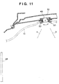
- the defroster outlet 44 comprises a grille 50 having an air guidance portion 49 which can change the air orientation, in the range from an outer position, where cool air is directed to a side window 48 of the vehicle interior as indicated by the arrow a in Fig. 11, to an inner position where cool air is directed inward in the vehicle interior as indicated by the arrow b.
- a flange 52 which is pressed against the bottom surface of a top sealing material 51 is formed. The flange 52 is secured with the periphery of the grille-placing hole, thereby concealing the grille 50.
- the fixing portion 45 of the roof duct 33 is formed by concaving the bottom wall surface 53 of the roof duct 33 toward the vehicle exterior, i.e., upward.
- the fixing portion 45 is fixed, while the concave insertion end 54 abuts against the top wall 55 of the roof duct 33, to the bottom surface of the roof reinforcement 40 by a fixing member such as a grip clamp or a screw or the like.
- the first outlets 46 for the first rear seat 2 are formed on a slanted wall 57 aslant upward toward the vehicle front as shown in Fig. 13, provided on the bottom wall of the first expanded portion 41 which ejects air to the front of the vehicle interior, so that cool air is ejected obliquely forward from the first outlets 46, i.e., ejected to the rear surface of the first rear seat 2.
- the second outlets 47 for the second rear seat 3 are formed on a slanted wall 58 aslant upward toward the vehicle rear, provided on the bottom wall of the second expanded portion 42 which ejects air to the rear portion of the vehicle interior, so that cool air is ejected obliquely backward from the second outlets 47, i.e., ejected to the front surface of the second rear seat 3.
- the first outlets 46 for the first rear seat 2 are arranged in the central portion of the vehicle width direction as shown in Fig. 14, so that cool air is ejected between the left and right separate-type first rear seats 2. Cool air, ejected from the second outlets 47 which are arranged on the back of the first outlets 46, is ejected to the center portion of the bench-type second rear seat 3. On the first and second outlets 46 and 47, grilles having air guidance portions for changing the cool-air ejection direction in the front-and-rear and left-and-right directions, are respectively provided.
- a vehicle having plural rows of seats e.g., three rows of seats 1 to 3 in the front-to-rear direction of the vehicle comprises the cooler duct 7 for guiding cool air from the cooler unit 5 to the portion above and between the first rear seat 2 positioned on the second row of seats from the vehicle front and the second rear seat 3 positioned behind the first rear seat 2.
- the cooler duct 7 comprises the first outlets 46 for ejecting cool air to the first rear seat 2 side, and the second outlets 47 for ejecting cool air to the second rear seat 3 side.
- the first outlets 46 are formed in a position away from the seated area of the first rear seat 2.
- the first and second rear seats 2 and 3 are constructed such that cool air is ejected to the first and second rear seats 2 and 3 respectively from the first and second outlets 46 and 47, formed on the row of roof duct 33 provided on the lower surface of the roof panel 30.
- cool air is more uniformly distributed and the wide area of the rear portion of the vehicle interior can be uniformly cooled without making the structure complicated as in the case of providing a plurality of ducts on the lower surface of the roof panel 30.
- first outlets 46 away from the seated area of the first rear seat 2 direct cool-air ejection toward the back of the head of the passenger who is seated on the first rear seat 2 is avoided. Therefore, the problem of "uncomfortable feeling" of passengers due to the localized air flow ejected to the back of the head of the passenger can be surely prevented.
- the first rear seat 2 positioned on the second row of seats from the vehicle front is a separate-type seat where the left and right seats are independent, and the first outlets 46 are arranged in the central portion of the roof duct 33 in the vehicle width direction.
- a passenger can easily move from the front seat 1 or the first rear seat 2 to the second rear seat 3.
- cool air is ejected from the first outlets 46 to the middle of the first rear seat 2 provided separately in the left and right.
- the rear portion of the vehicle interior is efficiently cooled, while preventing the problem of "uncomfortable feeling" of passengers due to the localized air flow ejected to the back of the passengers' heads.
- the second outlets 47 which ejects cool air to the front surface side of the bench-type second rear seat 3 situated in the last row of seats is arranged in the center portion of the vehicle width direction. Cool air, guided through the roof duct 33 to the center portion of the vehicle width direction, is ejected to the vehicle interior from the second outlets 46.
- the effect of adopting the above-described construction is significant because the aforementioned air conditioning unit 8, arranged in the rear portion of the vehicle, often employs an internal-air circulation type, in which heated air tends to circulate only in a part of the vehicle interior, rather than a fresh-air introducing type.
- the defroster outlets 44 having the grille 50 which includes the air guidance portion 49 for changing the air orientation in the range from the outer position, where cool air is directed to a side window 48 of the vehicle interior, to the inner position where cool air is directed inward in the vehicle interior, it is possible to select, as necessary, either a cooler-oriented state where the orientation of cool air ejected from the defroster outlets 44 is directed inward in the vehicle interior or a defrost-oriented state where the air ejection is directed to the side window 48.
- the cooler duct 6 comprises the vertical duct 29 extended upward from the cooler unit 5, the side duct 31 extended from the top end of the vertical duct 29 to the front side of the vehicle interior, and the roof duct 33 extended from the front end of the side duct 31 to the vehicle width direction. Cool air from the cooler unit 5 is guided through the vertical duct 29 to the upper portion of the vehicle interior, then guided toward the front side of the vehicle through the side duct 31, and further guided in the vehicle width direction through the roof duct 33 arranged above and between the first rear seat 2 and the second rear seat 3.
- the rear portion of the vehicle interior can be efficiently cooled without blocking the passengers' view. More specifically, even if the width (front-to-rear direction) of the D pillar 9 provided in the most rear of the vehicle is formed large, the view of the passengers seated on the seats 1 to 3 is not greatly affected. Therefore, the width of the D pillar 9 and the cooler duct 7 arranged along the D pillar 9 can be enlarged to reduce the flow resistance of cool air, while securing an enough opening area for the cooler duct 7, without negatively affecting the passengers' view. In addition, the strength of the D pillar 9 can be enhanced, thus the stability of the vehicle can be improved.
- the air conditioning unit 8 having the cooler unit 5 is provided between the lower portion of the D-pillar 9 provided in the most rear of the vehicle and the wheel housing 10 of the rear wheel, the air conditioning unit 8 can be appropriately arranged while efficiently utilizing the space provided on the side of the second rear seat 3 situated in the last row of seats. In addition, it is possible to secure space for arranging the rear door 11 in front of the air conditioning unit 8.
- the heater unit 4 is provided on the side of the second rear seat 3 in addition to the cooler unit 5, and the heater duct 6 is provided to guide the heated air from the heater unit 4 to the central portion of the vehicle width direction.
- the air conditioning apparatus according to the present embodiment does not limit the type of cars where it can be installed, and can efficiently heat the rear portion of the vehicle such as one-box type vehicle or the like.
- the air conditioning unit 8 having the heater unit 4 and cooler unit 5, on the side of the second rear seat 3, it is possible to secure space for providing the rear door 11 in front of the air conditioning unit 8, i.e., on the side of the first rear seat 2 located in the central portion of the vehicle front-to-rear direction. Therefore, not only a vehicle having a rear door on only one side of the vehicle body, but also a vehicle having the rear door 11 on both sides of the vehicle body can utilize the air conditioning apparatus having the above-described heater unit 4 and heater duct 6 and so on to efficiently cool or heat the rear portion of the vehicle interior.
- the heater duct 6 is arranged under the rear seat 3 situated in the last row of seats in the vehicle interior, and the outlet 17 is formed on the heater duct 6 for ejecting heated air upward from the floor to the vehicle interior.
- the heater duct 6 comprises: the first duct 12 extended downward from the heater unit 4 along the vehicle side wall; the second duct 14 extended from the bottom end of the first duct 12 to the central portion of the vehicle in the vehicle width direction, along the top surface of the floor panel 13; and a third duct 15 extended from the end portion of the second duct 14 toward the front portion of the vehicle.
- the outlet 17 for ejecting heated air is formed in the end portion of the third duct 15.
- a pair of branching parts 16 provided symmetrically with respect to the center line CL, are formed in the front portion of the third duct 15.
- heated air can be equally distributed by the branching parts 16 to the left and right of the vehicle width direction and ejected to the vehicle interior, while securing enough opening area of the third duct 15.
- a wide area of the rear portion of the vehicle interior can be uniformly heated.
- a child seat or the like may be fixed between the branching parts 16.
- the sound proof member 18 is provided on the top surface of the floor panel 13, and the heater duct 6 is buried in the sound proof member 18.
- the rug 19 on the heater duct 6 and the sound proof member 18 the bottom surface of the vehicle interior can be made flat while securing space for arranging the heater duct 6. Accordingly, when the second rear seat 3 is removed and the place for the heater duct 6 is used as a trunk room, the storability of luggage can be effectively improved.
- the hollow 23 is formed on the floor panel 13 in the rear portion of the vehicle interior to stow the seat bottom and seat back of the second rear seat 3 integrally when the seat is pushed back.
- the air conditioning unit 8 is arranged in the side of the hollow 23.
Landscapes
- Physics & Mathematics (AREA)
- Thermal Sciences (AREA)
- Engineering & Computer Science (AREA)
- Mechanical Engineering (AREA)
- Air-Conditioning For Vehicles (AREA)
- Seats For Vehicles (AREA)
Applications Claiming Priority (2)
| Application Number | Priority Date | Filing Date | Title |
|---|---|---|---|
| JP6361098 | 1998-03-13 | ||
| JP06361098A JP3622483B2 (ja) | 1998-03-13 | 1998-03-13 | 車両の空調装置 |
Publications (3)
| Publication Number | Publication Date |
|---|---|
| EP0941879A2 true EP0941879A2 (fr) | 1999-09-15 |
| EP0941879A3 EP0941879A3 (fr) | 2001-02-28 |
| EP0941879B1 EP0941879B1 (fr) | 2004-09-29 |
Family
ID=13234248
Family Applications (1)
| Application Number | Title | Priority Date | Filing Date |
|---|---|---|---|
| EP99101715A Expired - Lifetime EP0941879B1 (fr) | 1998-03-13 | 1999-02-10 | Installation de climatisation de véhicule |
Country Status (5)
| Country | Link |
|---|---|
| US (2) | US6120370A (fr) |
| EP (1) | EP0941879B1 (fr) |
| JP (1) | JP3622483B2 (fr) |
| DE (1) | DE69920556T2 (fr) |
| ES (1) | ES2229563T3 (fr) |
Cited By (2)
| Publication number | Priority date | Publication date | Assignee | Title |
|---|---|---|---|---|
| EP1120300A3 (fr) * | 2000-01-28 | 2004-01-02 | Zexel Valeo Climate Control Corporation | Système de conditionnement d'air de véhicule automobile |
| US6932693B2 (en) | 2001-07-24 | 2005-08-23 | Mitsubishi Heavy Industries, Ltd. | Air-conditioning apparatus |
Families Citing this family (53)
| Publication number | Priority date | Publication date | Assignee | Title |
|---|---|---|---|---|
| US6131652A (en) * | 1997-07-30 | 2000-10-17 | Denso Corporation | Air conditioning apparatus for vehicle |
| DE10056955B4 (de) * | 1999-11-19 | 2010-02-18 | Honda Giken Kogyo K.K. | Fahrzeugklimaanlage und Deckenstruktur für ein Fahrzeug mit Klimaanlage |
| JP3578952B2 (ja) * | 1999-11-26 | 2004-10-20 | 本田技研工業株式会社 | 車両のエアダクト及びガーニッシュ構造 |
| JP4508483B2 (ja) * | 2001-07-25 | 2010-07-21 | 三菱重工業株式会社 | 車両用空気調和装置 |
| US7083016B2 (en) * | 2001-08-23 | 2006-08-01 | General Motors Corporation | Mobile chassis and interchangeable vehicle body with waste heat rejection system |
| US9963056B2 (en) * | 2001-09-20 | 2018-05-08 | Kurabe Industrial Co., Ltd. | Seat heater and a manufacturing method of seat heater |
| JP2003252031A (ja) * | 2002-03-05 | 2003-09-09 | Nippon Plast Co Ltd | 車両用ダクトの固定構造 |
| US6749255B2 (en) * | 2002-06-21 | 2004-06-15 | Lear Corporation | Blow molded multiple function assemblies for vehicle headliners |
| JP2004148970A (ja) * | 2002-10-30 | 2004-05-27 | Denso Corp | 車両空調用天井吹出装置 |
| US7223948B2 (en) * | 2002-11-15 | 2007-05-29 | W.E.T. Automotive Systems Ag | Covered conductor and heater formed therewith |
| US7137992B2 (en) * | 2002-12-09 | 2006-11-21 | Qi Zhang | Mind stimulator |
| DE10310022B4 (de) * | 2003-02-28 | 2017-02-16 | Volkswagen Ag | Vorrichtung und Verfahren für eine Klimatisierung der hinteren Sitzplätze in einem Fahrzeug |
| JP3980504B2 (ja) | 2003-03-18 | 2007-09-26 | 本田技研工業株式会社 | 車両用空調ダクト構造 |
| US20050011640A1 (en) * | 2003-07-17 | 2005-01-20 | Mazda Motor Corporation | Air conditioner for vehicle |
| US6899614B1 (en) * | 2003-12-08 | 2005-05-31 | Behr Gmbh & Co. | Ventilation unit for a motor vehicle |
| US7587901B2 (en) * | 2004-12-20 | 2009-09-15 | Amerigon Incorporated | Control system for thermal module in vehicle |
| JP4569428B2 (ja) * | 2005-09-12 | 2010-10-27 | 株式会社デンソー | 液晶表示装置 |
| US20070123157A1 (en) * | 2005-11-30 | 2007-05-31 | Shah Sanjay M | Structurally-integrated HVAC duct |
| US20080087316A1 (en) | 2006-10-12 | 2008-04-17 | Masa Inaba | Thermoelectric device with internal sensor |
| US20090042501A1 (en) * | 2007-08-07 | 2009-02-12 | Hung Stephen T | Localized Air Distribution System |
| US7877827B2 (en) | 2007-09-10 | 2011-02-01 | Amerigon Incorporated | Operational control schemes for ventilated seat or bed assemblies |
| KR101779870B1 (ko) | 2008-02-01 | 2017-10-10 | 젠썸 인코포레이티드 | 열전 소자용 응결 센서 및 습도 센서 |
| JP5997899B2 (ja) | 2008-07-18 | 2016-09-28 | ジェンサーム インコーポレイテッドGentherm Incorporated | 空調されるベッドアセンブリ |
| DE102009008274A1 (de) * | 2009-02-10 | 2010-08-12 | GM Global Technology Operations, Inc., Detroit | Ablaufschlauchsystem für eine Kraftfahrzeug-Klimaanlage |
| US8632382B2 (en) * | 2009-07-23 | 2014-01-21 | Toyota Motor Engineering & Manufacturing North America, Inc. | Vehicle air system assemblies with aircap assemblies |
| JP5479195B2 (ja) * | 2010-04-20 | 2014-04-23 | 株式会社クボタ | キャビンのエアコン用ダクト装置 |
| US8485589B2 (en) | 2010-03-30 | 2013-07-16 | Kubota Corporation | Cabin system |
| WO2012094719A1 (fr) | 2011-01-12 | 2012-07-19 | Salflex Polymers Ltd. | Objet creux doté d'éléments structuraux |
| JP5367884B2 (ja) * | 2011-08-31 | 2013-12-11 | キョーラク株式会社 | 板状部分付き管状発泡成形体及びその成形方法 |
| WO2013052823A1 (fr) | 2011-10-07 | 2013-04-11 | Gentherm Incorporated | Commandes de dispositif thermoélectrique et procédés associés |
| US9989267B2 (en) | 2012-02-10 | 2018-06-05 | Gentherm Incorporated | Moisture abatement in heating operation of climate controlled systems |
| US9168810B2 (en) * | 2012-10-09 | 2015-10-27 | Delphi Technologies, Inc. | Heating and cooling system for occupants of the rear portion of a vehicle |
| US9682608B2 (en) * | 2013-01-30 | 2017-06-20 | Hanon Systems | Supplemental heating and cooling sources for a heating, ventilation and air conditioning system |
| US9662962B2 (en) | 2013-11-05 | 2017-05-30 | Gentherm Incorporated | Vehicle headliner assembly for zonal comfort |
| KR102252584B1 (ko) | 2014-02-14 | 2021-05-14 | 젠썸 인코포레이티드 | 전도식 대류식 기온 제어 조립체 |
| DE102014209323A1 (de) * | 2014-05-16 | 2015-11-19 | Mahle International Gmbh | Kunststoffbauteil |
| US10414302B2 (en) | 2014-10-17 | 2019-09-17 | Gentherm Incorporated | Climate control systems and methods |
| US11033058B2 (en) | 2014-11-14 | 2021-06-15 | Gentherm Incorporated | Heating and cooling technologies |
| US11639816B2 (en) | 2014-11-14 | 2023-05-02 | Gentherm Incorporated | Heating and cooling technologies including temperature regulating pad wrap and technologies with liquid system |
| US11857004B2 (en) | 2014-11-14 | 2024-01-02 | Gentherm Incorporated | Heating and cooling technologies |
| US10787060B1 (en) * | 2016-09-21 | 2020-09-29 | Apple Inc. | Body structure ventilation |
| US10766339B2 (en) * | 2017-01-26 | 2020-09-08 | Ford Global Technologies, Llc | Vehicle structural air duct |
| US20200023708A1 (en) * | 2018-07-19 | 2020-01-23 | Ford Global Technologies, Llc | A conditioned air distribution system for a vehicle |
| US11223004B2 (en) | 2018-07-30 | 2022-01-11 | Gentherm Incorporated | Thermoelectric device having a polymeric coating |
| CN121230238A (zh) | 2018-11-30 | 2025-12-30 | 金瑟姆股份公司 | 热电调节系统和方法 |
| US11152557B2 (en) | 2019-02-20 | 2021-10-19 | Gentherm Incorporated | Thermoelectric module with integrated printed circuit board |
| EP4031824A4 (fr) * | 2019-09-18 | 2024-02-14 | Canoo Technologies Inc. | Systèmes de gestion thermique pour plateformes de véhicules électriques |
| JP7243559B2 (ja) * | 2019-10-02 | 2023-03-22 | トヨタ自動車株式会社 | 車両用の空調ダクト |
| DE202019107074U1 (de) | 2019-12-18 | 2021-03-19 | Rehau Ag + Co | Luftführungsanordnung |
| US12552223B2 (en) | 2021-03-18 | 2026-02-17 | Gentherm Incorporated | Optimal control of convective thermal devices |
| US12611909B2 (en) | 2021-03-18 | 2026-04-28 | Gentherm Incorporated | Preconditioning surfaces using intelligent thermal effectors |
| DE102021002173B4 (de) | 2021-04-26 | 2023-03-23 | Truma Gerätetechnik GmbH & Co. KG | Klimagerät |
| DE102022119305B3 (de) | 2022-08-02 | 2023-09-07 | Audi Aktiengesellschaft | Kraftfahrzeug mit Klimatisierungseinheit in säulenartigem Rahmenelement |
Citations (2)
| Publication number | Priority date | Publication date | Assignee | Title |
|---|---|---|---|---|
| JPS57144118A (en) | 1981-02-28 | 1982-09-06 | Nissan Motor Co Ltd | Air conditioner |
| JPS6045210U (ja) | 1983-09-07 | 1985-03-30 | 三菱重工業株式会社 | 自動車用空調装置 |
Family Cites Families (10)
| Publication number | Priority date | Publication date | Assignee | Title |
|---|---|---|---|---|
| JPS5815204Y2 (ja) * | 1978-04-11 | 1983-03-28 | 日産自動車株式会社 | 車両用空気吹出し装置 |
| CH673051A5 (fr) | 1986-07-08 | 1990-01-31 | Escher Wyss Ag | |
| IT212713Z2 (it) * | 1987-10-30 | 1989-08-28 | Fiat Auto Spa | Dispositivo di climatizzazione per una zona posteriore di un abitacolo di un veicolo |
| JPH02126916A (ja) | 1988-11-04 | 1990-05-15 | Kurita Water Ind Ltd | 脱臭装置 |
| US5054378A (en) * | 1990-07-20 | 1991-10-08 | Speece Donald R | Combination commuter van and air conditioner system therefor |
| US5167129A (en) * | 1990-07-26 | 1992-12-01 | Calsonic Corporation | Automotive air conditioning system |
| US5399121A (en) * | 1994-02-28 | 1995-03-21 | General Motors Corporation | Vehicle air distribution system with improved space utilization |
| FR2717427B1 (fr) * | 1994-03-17 | 1996-04-19 | Renault | Installation de climatisation de véhicule automobile. |
| JP3658838B2 (ja) * | 1996-03-01 | 2005-06-08 | 株式会社デンソー | 車両用空調装置 |
| JP3726389B2 (ja) * | 1996-12-04 | 2005-12-14 | 株式会社デンソー | 車両用検出装置 |
-
1998
- 1998-03-13 JP JP06361098A patent/JP3622483B2/ja not_active Expired - Fee Related
-
1999
- 1999-02-10 ES ES99101715T patent/ES2229563T3/es not_active Expired - Lifetime
- 1999-02-10 EP EP99101715A patent/EP0941879B1/fr not_active Expired - Lifetime
- 1999-02-10 DE DE69920556T patent/DE69920556T2/de not_active Expired - Lifetime
- 1999-02-17 US US09/251,416 patent/US6120370A/en not_active Expired - Fee Related
-
2000
- 2000-06-27 US US09/604,258 patent/US6318102B1/en not_active Expired - Fee Related
Patent Citations (2)
| Publication number | Priority date | Publication date | Assignee | Title |
|---|---|---|---|---|
| JPS57144118A (en) | 1981-02-28 | 1982-09-06 | Nissan Motor Co Ltd | Air conditioner |
| JPS6045210U (ja) | 1983-09-07 | 1985-03-30 | 三菱重工業株式会社 | 自動車用空調装置 |
Cited By (3)
| Publication number | Priority date | Publication date | Assignee | Title |
|---|---|---|---|---|
| EP1120300A3 (fr) * | 2000-01-28 | 2004-01-02 | Zexel Valeo Climate Control Corporation | Système de conditionnement d'air de véhicule automobile |
| US6932693B2 (en) | 2001-07-24 | 2005-08-23 | Mitsubishi Heavy Industries, Ltd. | Air-conditioning apparatus |
| DE10292915B3 (de) * | 2001-07-24 | 2006-01-05 | Mitsubishi Heavy Industries, Ltd. | Luftverteilung für eine Klimaanlage |
Also Published As
| Publication number | Publication date |
|---|---|
| US6318102B1 (en) | 2001-11-20 |
| US6120370A (en) | 2000-09-19 |
| JP3622483B2 (ja) | 2005-02-23 |
| ES2229563T3 (es) | 2005-04-16 |
| JPH11254948A (ja) | 1999-09-21 |
| EP0941879A3 (fr) | 2001-02-28 |
| DE69920556T2 (de) | 2005-10-13 |
| EP0941879B1 (fr) | 2004-09-29 |
| DE69920556D1 (de) | 2004-11-04 |
Similar Documents
| Publication | Publication Date | Title |
|---|---|---|
| EP0941879B1 (fr) | Installation de climatisation de véhicule | |
| US7866722B2 (en) | Console box | |
| US7641266B2 (en) | Central pillar and ducting for automotive vehicle | |
| US6520849B1 (en) | Integrated structural HVAC system | |
| GB2338459A (en) | Tunnel panelling arrangement for a motor vehicle | |
| JP3614058B2 (ja) | 車両用空気調和装置 | |
| US7328918B2 (en) | Seat belt device for vehicle | |
| US11260721B2 (en) | Motor vehicle | |
| JP3651237B2 (ja) | 車両の空調装置 | |
| KR101264614B1 (ko) | 자동차용 후석 공조시스템 | |
| JP3646505B2 (ja) | 車両の空調装置 | |
| JP3629938B2 (ja) | 車両の空調装置 | |
| JP3622482B2 (ja) | 車両の空調装置 | |
| JP3800451B2 (ja) | 自動車用空気調和装置 | |
| JP4801811B2 (ja) | 吹出しグリル | |
| JPH0623450Y2 (ja) | 自動車用空調装置のエア吹出構造 | |
| KR20220169092A (ko) | 차량용 공조장치 | |
| JP3792367B2 (ja) | 空気調和装置のフットダクト構造 | |
| JP2000355211A (ja) | 車両用空調装置 | |
| JP4487162B2 (ja) | 車両の空調装置 | |
| CN214355429U (zh) | 用于车辆的通风装置、包括该通风装置的车门及相关车辆 | |
| KR100925653B1 (ko) | 자동차용 공기조화장치의 케이스 | |
| JP4487163B2 (ja) | 車両の空調装置 | |
| JP2008018918A (ja) | 車両の空調装置 | |
| JP2001225630A (ja) | 自動車用の空気調和ユニット |
Legal Events
| Date | Code | Title | Description |
|---|---|---|---|
| PUAI | Public reference made under article 153(3) epc to a published international application that has entered the european phase |
Free format text: ORIGINAL CODE: 0009012 |
|
| AK | Designated contracting states |
Kind code of ref document: A2 Designated state(s): DE ES FR GB IT |
|
| AX | Request for extension of the european patent |
Free format text: AL;LT;LV;MK;RO;SI |
|
| PUAL | Search report despatched |
Free format text: ORIGINAL CODE: 0009013 |
|
| AK | Designated contracting states |
Kind code of ref document: A3 Designated state(s): AT BE CH CY DE DK ES FI FR GB GR IE IT LI LU MC NL PT SE |
|
| AX | Request for extension of the european patent |
Free format text: AL;LT;LV;MK;RO;SI |
|
| 17P | Request for examination filed |
Effective date: 20010712 |
|
| AKX | Designation fees paid |
Free format text: DE ES FR GB IT |
|
| 17Q | First examination report despatched |
Effective date: 20030429 |
|
| GRAP | Despatch of communication of intention to grant a patent |
Free format text: ORIGINAL CODE: EPIDOSNIGR1 |
|
| GRAS | Grant fee paid |
Free format text: ORIGINAL CODE: EPIDOSNIGR3 |
|
| GRAA | (expected) grant |
Free format text: ORIGINAL CODE: 0009210 |
|
| AK | Designated contracting states |
Kind code of ref document: B1 Designated state(s): DE ES FR GB IT |
|
| REG | Reference to a national code |
Ref country code: GB Ref legal event code: FG4D |
|
| REF | Corresponds to: |
Ref document number: 69920556 Country of ref document: DE Date of ref document: 20041104 Kind code of ref document: P |
|
| ET | Fr: translation filed | ||
| REG | Reference to a national code |
Ref country code: ES Ref legal event code: FG2A Ref document number: 2229563 Country of ref document: ES Kind code of ref document: T3 |
|
| PLBE | No opposition filed within time limit |
Free format text: ORIGINAL CODE: 0009261 |
|
| STAA | Information on the status of an ep patent application or granted ep patent |
Free format text: STATUS: NO OPPOSITION FILED WITHIN TIME LIMIT |
|
| 26N | No opposition filed |
Effective date: 20050630 |
|
| PGFP | Annual fee paid to national office [announced via postgrant information from national office to epo] |
Ref country code: ES Payment date: 20090302 Year of fee payment: 11 |
|
| PGFP | Annual fee paid to national office [announced via postgrant information from national office to epo] |
Ref country code: GB Payment date: 20090204 Year of fee payment: 11 |
|
| PGFP | Annual fee paid to national office [announced via postgrant information from national office to epo] |
Ref country code: IT Payment date: 20090216 Year of fee payment: 11 |
|
| PGFP | Annual fee paid to national office [announced via postgrant information from national office to epo] |
Ref country code: FR Payment date: 20090213 Year of fee payment: 11 |
|
| GBPC | Gb: european patent ceased through non-payment of renewal fee |
Effective date: 20100210 |
|
| REG | Reference to a national code |
Ref country code: FR Ref legal event code: ST Effective date: 20101029 |
|
| PG25 | Lapsed in a contracting state [announced via postgrant information from national office to epo] |
Ref country code: FR Free format text: LAPSE BECAUSE OF NON-PAYMENT OF DUE FEES Effective date: 20100301 |
|
| REG | Reference to a national code |
Ref country code: ES Ref legal event code: FD2A Effective date: 20110308 |
|
| PG25 | Lapsed in a contracting state [announced via postgrant information from national office to epo] |
Ref country code: IT Free format text: LAPSE BECAUSE OF NON-PAYMENT OF DUE FEES Effective date: 20100210 Ref country code: GB Free format text: LAPSE BECAUSE OF NON-PAYMENT OF DUE FEES Effective date: 20100210 |
|
| PGFP | Annual fee paid to national office [announced via postgrant information from national office to epo] |
Ref country code: DE Payment date: 20110208 Year of fee payment: 13 |
|
| PG25 | Lapsed in a contracting state [announced via postgrant information from national office to epo] |
Ref country code: ES Free format text: LAPSE BECAUSE OF NON-PAYMENT OF DUE FEES Effective date: 20110307 |
|
| PG25 | Lapsed in a contracting state [announced via postgrant information from national office to epo] |
Ref country code: ES Free format text: LAPSE BECAUSE OF NON-PAYMENT OF DUE FEES Effective date: 20100211 |
|
| REG | Reference to a national code |
Ref country code: DE Ref legal event code: R119 Ref document number: 69920556 Country of ref document: DE Effective date: 20120901 |
|
| PG25 | Lapsed in a contracting state [announced via postgrant information from national office to epo] |
Ref country code: DE Free format text: LAPSE BECAUSE OF NON-PAYMENT OF DUE FEES Effective date: 20120901 |