EP0943507A2 - Rétracteur de sangle pour un système de ceinture de sécurité de véhicule - Google Patents
Rétracteur de sangle pour un système de ceinture de sécurité de véhicule Download PDFInfo
- Publication number
- EP0943507A2 EP0943507A2 EP99104090A EP99104090A EP0943507A2 EP 0943507 A2 EP0943507 A2 EP 0943507A2 EP 99104090 A EP99104090 A EP 99104090A EP 99104090 A EP99104090 A EP 99104090A EP 0943507 A2 EP0943507 A2 EP 0943507A2
- Authority
- EP
- European Patent Office
- Prior art keywords
- belt
- sensor
- belt retractor
- blocking
- retractor according
- Prior art date
- Legal status (The legal status is an assumption and is not a legal conclusion. Google has not performed a legal analysis and makes no representation as to the accuracy of the status listed.)
- Granted
Links
- 230000000903 blocking effect Effects 0.000 claims description 72
- 230000006835 compression Effects 0.000 claims description 9
- 238000007906 compression Methods 0.000 claims description 9
- 238000004804 winding Methods 0.000 claims description 8
- 239000000523 sample Substances 0.000 claims description 3
- 238000010304 firing Methods 0.000 description 4
- 230000004913 activation Effects 0.000 description 3
- 230000001960 triggered effect Effects 0.000 description 3
- 238000010276 construction Methods 0.000 description 1
- 238000006073 displacement reaction Methods 0.000 description 1
- 230000000694 effects Effects 0.000 description 1
- 238000005516 engineering process Methods 0.000 description 1
- 238000009434 installation Methods 0.000 description 1
- 230000036316 preload Effects 0.000 description 1
Images


Classifications
-
- B—PERFORMING OPERATIONS; TRANSPORTING
- B60—VEHICLES IN GENERAL
- B60R—VEHICLES, VEHICLE FITTINGS, OR VEHICLE PARTS, NOT OTHERWISE PROVIDED FOR
- B60R22/00—Safety belts or body harnesses in vehicles
- B60R22/34—Belt retractors, e.g. reels
- B60R22/46—Reels with means to tension the belt in an emergency by forced winding up
- B60R22/4628—Reels with means to tension the belt in an emergency by forced winding up characterised by fluid actuators, e.g. pyrotechnic gas generators
- B60R22/4652—Mechanical triggering means therefor
Definitions
- the invention relates to a belt retractor for a vehicle seat belt system, with a Belt reel that holds the seat belt, a belt tensioning mechanism that holds the belt reel in the webbing winding direction, and a sensor that the Belt tightening mechanism can trigger and is provided with a safety device that by assembling the belt retractor in a vehicle from a secured state in which the sensor is blocked, can be brought into a release state in which the sensor is ready for triggering, the safety device having a sensor blocking element, that between a blocking position in which the sensor is blocked and a release position is movable, in which the sensor is ready to trigger.
- Such a belt retractor is, for example, from European patent application 0 456 853 known.
- the belt tensioning mechanism which is triggered by the sensor when needed, serves in addition, by rotating the belt reel in the webbing winding direction, the so-called belt slack from the seat belt system so that a vehicle occupant from the earliest possible Time at which the vehicle decelerates.
- the sensor blocking element is provided, which is in its blocking position an inertial mass of the sensor is blocked.
- the sensor blocking element is in its Release position transferred when the belt retractor is attached to the vehicle. This can happen, for example, by means of a stylus that is attached to the belt retractor when it is being installed part of the vehicle comes to rest and pressed into the housing of the belt retractor becomes.
- a disadvantage of this known belt retractor is that no possibility is provided for a Prevent activation of the belt tensioning mechanism when the seat belt is not in use becomes. In the event of an accident, the belt tensioning mechanism will also work actuated when, for example, the corresponding belt retractor is provided for the front passenger seat and the passenger seat is vacant.
- the object of the invention is to a belt retractor of the type mentioned create in a simple way a transport lock that activates the belt tensioning mechanism prevented if the belt retractor is not installed in a vehicle, is combined with an occupancy sensor that triggers the belt tensioning mechanism prevents when the seat belt of the retractor is not used.
- the Safety device additionally has a transport securing element and a touch element, that the probe element the diameter of the belt reel located on the belt reel scans and a movement of the sensor blocking element in the release position only when the diameter falls short of a predetermined that the transport securing element is movable between a securing position and a release position, wherein a spring is provided which the transport securing element in the securing position acts that a spring is provided which the sensor blocking element in the release position acted upon, and that the transport securing element has a holding section has, which in the securing position on a locking portion of the sensor blocking element attacks and holds it in the blocking position.
- the Sensor blocking element one and the same component to trigger the belt tensioning mechanism both when the belt retractor is not installed in a vehicle, as to prevent even if the corresponding seat belt is not used. This leads to particularly low construction costs.
- the transport securing element and the sensor blocking element are designed as a slide.
- Storage with translation ensures with great certainty that that even after a lifespan of up to 15 years, all components are still in the desired Function in such a way that the sensor is automatically secured when the Belt retractor is removed from the vehicle again.
- the springs are compression springs are. This offers a higher level of security than the leaf springs, which are usually stationary of technology can be used. Leaf springs settle during the long time that a belt retractor can be installed in the vehicle, more than compression springs, so that by the Use of pressure springs with higher security ensures that the sensor too is secured again when the belt retractor is removed.
- FIG. 1 to 4 schematically show a belt retractor according to a first embodiment shown the invention, the parts in Figures 1 and 4 for better clarity of the belt retractor were omitted, which are not necessary for understanding the invention are.
- the belt retractor contains a belt reel, which is schematically recorded on it Belt roll 10 is indicated. Starting from this webbing winding the seat belt 12, which is available to a vehicle occupant.
- the belt spool is rotatably mounted in a frame 14 by means of a threaded extension 16, in which a Can engage fastening screw, can be attached to a vehicle.
- a belt tensioning mechanism 18, not shown in detail, is provided in a housing, which, after activation, the belt reel and thus the belt webbing 10 in the webbing winding direction can rotate so that the seatbelt of a seat belt system is added becomes.
- the belt tensioning mechanism can be of any configuration; it can act, for example, a pyrotechnically driven linear drive, which has a Pull rope or a rack acts on the belt reel, or around a rotary piston drive. The specific configuration is not of interest for understanding the invention.
- the belt tensioning mechanism is, if necessary, a mechanical sensor 20 (see also Figures 17 and 18) triggered.
- the sensor 20 has a translationally displaceable inertial mass 22 on, from their rest position shown in Figure 17 by means of a of the arrow P acting delay are moved into their release position shown in FIG can.
- the sensor also contains an intermediate element 24 which is slidably mounted and after the inertial mass 22 a predetermined idle stroke from its rest position Has taken the trigger position, is taken away by this.
- the intermediate element 24 has a nose 25, the function of which will be explained later, and one Provide projection 26, on which the free end 28 of a in the rest position Support lever 30 supports.
- a plunger is supported on a projection 32 of the support lever 30 34, which rests with a conical end on a locking cone 36 of a firing pin 38. In the rest position shown in Figure 17, the plunger 34 holds the firing pin 38 in one biased position.
- the plunger 34 can be moved out of its position shown in FIG a thrust effect is applied, which is caused by the conical end of the plunger on the locking cone 36 of the firing pin 38 results.
- the firing pin on a detonator of the belt tightening mechanism, not shown act, whereupon this is activated.
- a safety device which ensures that the belt tensioning mechanism can only be activated if the belt retractor is in accordance with the regulations Vehicle installed and also the seat belt from a vehicle occupant is created.
- This safety device contains a as a sensor blocking slide trained sensor blocking element 40, which is translationally displaceable in the sensor 20 is attached.
- the sensor blocking slide 40 can between a blocking position in the he engages the nose 25 of the intermediate element 24 and this in his shown in Figure 17 Holds position, and a release position in which the intermediate element 24th from its position shown in FIG. 17 to its position shown in FIG. 18 can.
- the sensor blocking slide 40 is moved into its release position by a compression spring 42 in which it continues from sensor 20 with respect to FIGS. 2 and 3 protrudes than in its blocking position.
- the sensor blocking slide 40 is provided with a sensing element 44, which is in one piece is designed with the sensor blocking slide 40 trained nose.
- the feeler element 44 serves to scan the diameter of the webbing roll 10.
- a locking section 46 is formed on the sensor blocking slide 40 which surface at an angle of 45 ° to the direction of adjustment of the sensor blocking slide having.
- a guide 48 is provided around the feeler element 44, which is on a cover 50 of the sensor 20 is attached.
- a transport securing element designed as a transport securing slide 52 provided, which serves to lock the sensor 20 when the belt retractor is not properly installed in a vehicle.
- the transport safety slide 52 is translationally displaceable between a securing position and a release position attached in a guide 54, which is also formed on the cover 50 of the sensor 20 is.
- the transport securing slide 52 is moved into its securing position by a compression spring 56 applied to the thread extension 16.
- the bias of the spring 56 of the Transport securing slide 52 is greater than the preload of the spring 42 of the sensor blocking slide 40.
- the transport securing slide 52 can be removed from this securing position in a direction perpendicular to the direction of movement of the sensor blocking slide 40 with respect to Figure 3 can be adjusted to the right in the release position.
- a holding section 58 is formed, one with respect to the direction of movement of the transport securing slide 52 has an oriented surface at an angle of 45 °. This Surface is parallel to the surface of the locking section formed on sensor blocking slide 40 46 aligned.
- the belt retractor is shown in a state in which it is not in a vehicle is installed and in which no belt strap is pulled off the belt retractor.
- the belt webbing 10 therefore has its maximum diameter.
- the transport safety slide 52 in its securing position in contact with the threaded extension 16, in which the holding section 58 on the locking section 46 of the sensor blocking slide 40 supports. Since the two abutting surfaces of the holding section and of the locking section 46 at an angle of 45 ° to the direction of movement of the transport securing slide 52 or the sensor blocking slide 40 are inclined, the sensor blocking slide 40 pressed against the action by its spring 42 into the blocking position, in which the intermediate element 24 is secured in the position shown in FIG.
- the feeler element 44 bears against the belt webbing 10.
- the feeler element 44 is like this dimension that in this state, the sensor blocking slide 40 from the webbing 10 the push button 44 is pressed into the blocking position.
- the sensor blocking slide 40 is therefore loaded twice into its blocking position: on the one hand by the transport safety slide 52 via the holding section 58 and the locking section 46 and the other by the sensing element 44. In this way, the sensor is safely and reliably prevented in the event of bumps that occur during transport or handling of the belt retractor can trigger the belt tensioning mechanism.
- FIGS. 5 to 8 show the belt retractor in a second state.
- the same reference numerals are used, so that on the description there can be referenced.
- FIGS. 9 to 12 show the belt retractor in a third state. Also be here used the same reference numerals for the already known components, so that on the preceding description can be referenced.
- the sensor 20 is not secured, so that the belt tensioning mechanism triggered by a corresponding delay in the direction of arrow P. could be.
- the transport safety slide 52 is by means of a fastening screw 60, which is screwed into the threaded extension 16, from its securing position into the release position in which the holding section 58 is no longer on the locking section 46 of the sensor blocking slide attacks.
- a certain amount of webbing is from Belt retractor deducted so that the webbing roll 10 has a diameter of one falls below a predetermined diameter. From this predetermined diameter is the Sensor blocking slide 40 under the action of the spring 42 acting on it so far Belt reel moved into its release position so that it is no longer on the nose 25 of the intermediate element 24 attacks.
- the intermediate element can therefore from the inertial mass be taken when they move from their rest position to the release position becomes.
- the belt tensioning mechanism to be activated.
- FIGS. 13 to 16 show the belt retractor in a fourth state.
- the same reference numerals are used for the already known components, so that on the previous explanations can be referenced.
- the belt retractor is in a vehicle by means of the fastening screw 60 attached, but no webbing is removed from the retractor. That state is, for example, when the seat belt retractor is the seat belt for the front passenger seat and the passenger seat is either unoccupied or the vehicle occupant sitting there is not wearing a seat belt.
- this prevents the webbing from winding 10 adjacent probe 44 that the sensor blocking slide 40 by its spring 42 from the Blocking position is pressed into the release position. This prevents the sensor blocking slide 40 that the intermediate element 24 is carried by the inertial mass 22.
- the spring 56 ensures that the transport locking slide 52 is returned to its locking position is moved.
- the sensor blocking slide 40 is by means of the holding section 58 and the locking portion 46 pressed into the blocking position, in the activation the belt tightening mechanism is prevented. Since the transport safety slide 52 and the sensor blocking slide 40 are both mounted for translational displacement and the two Springs 56 and 42 are compression springs, which at most experience very little settling over time, is guaranteed even after a long installation time of 15 years, for example, that the sensor 20 is reliably secured when dismantling the belt retractor.
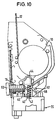
- 19 to 21 is a belt retractor according to a second embodiment of the invention shown.
- the transport securing element is used as a transport securing lever 152 formed, which is rotatably mounted on a pin 151 and a with respect to FIG has an upwardly bent end 153.
- the transport lock lever 152 is one Compression spring 156 in its securing position, with respect to Figure 19 downward.
- a holding section 158 At the Transport securing lever 152 is formed a holding section 158, which is located on the locking section 46 of the sensor blocking slide 40 supports and this against the action presses by its spring 42 into the blocking position.
- the transport securing lever 152 is shown from its securing position, which is shown in FIG. 19 by screwing the fastening screw 60 into its release position shown in FIG brought with the fastening screw 60 on the cranked end 153 of the transport securing lever 152 slides along and prints it upward with respect to FIG. 20.
- the holding section 158 releases the sensor blocking slide 40, which is now under the action the spring 42 acting on it is displaced towards the webbing winding 10.
- the Sensor blocking slide 40 lies with its sensing element 44 on the belt webbing 10 so that it has its release position at a predetermined diameter, as in FIG. 21 shown, achieved.
- the other function corresponds to that of the belt retractor according to the first Embodiment.
- the sensor blocking element is designed as a sensor blocking lever 140, which is rotatably mounted on a pin 141 and by the spring 42 of one, in Figure 22, blocking position shown can be pivoted into a release position, which in Figure 24 is shown.
- a locking section 146 in the form of a is on the sensor blocking lever 140 Pin formed on which the holding portion 58 of the transport lock slide 52 supports.
- the sensor blocking lever 140 At its end facing away from the intermediate element 24 is the sensor blocking lever 140 provided with a feeler element 44 which is in one piece with the sensor blocking lever 140 trained nose is executed.
- the feeler element 44 serves the diameter to scan the webbing 10.
- the transport securing slide 52 is in its securing position, in which the holding section 58 of the transport safety slide 52 on the locking section 146 rests and thereby the sensor blocking lever 140 against the force of the compression spring 42 holds in the blocking position.
- the holding portion 58 releases the locking portion 146 so that the sensor blocking lever 140 can rest on the webbing winding 10 with its feeler element 44.
- the compression spring 42 pivots the sensor blocking lever 140 in the direction of the belt webbing 10 until the sensor lock lever 140 starts from a predetermined value of the diameter has reached its release position, as shown in FIG.
- the further function corresponds to that of the belt retractor according to the first embodiment.
Landscapes
- Engineering & Computer Science (AREA)
- Mechanical Engineering (AREA)
- Automotive Seat Belt Assembly (AREA)
Applications Claiming Priority (2)
| Application Number | Priority Date | Filing Date | Title |
|---|---|---|---|
| DE29805084U DE29805084U1 (de) | 1998-03-20 | 1998-03-20 | Gurtaufroller für ein Fahrzeug-Sicherheitsgurtsystem |
| DE29805084U | 1998-03-20 |
Publications (3)
| Publication Number | Publication Date |
|---|---|
| EP0943507A2 true EP0943507A2 (fr) | 1999-09-22 |
| EP0943507A3 EP0943507A3 (fr) | 2002-06-12 |
| EP0943507B1 EP0943507B1 (fr) | 2004-05-26 |
Family
ID=8054507
Family Applications (1)
| Application Number | Title | Priority Date | Filing Date |
|---|---|---|---|
| EP99104090A Expired - Lifetime EP0943507B1 (fr) | 1998-03-20 | 1999-03-18 | Rétracteur de sangle pour un système de ceinture de sécurité de véhicule |
Country Status (5)
| Country | Link |
|---|---|
| US (1) | US6186431B1 (fr) |
| EP (1) | EP0943507B1 (fr) |
| JP (1) | JPH11321557A (fr) |
| DE (2) | DE29805084U1 (fr) |
| ES (1) | ES2222003T3 (fr) |
Families Citing this family (5)
| Publication number | Priority date | Publication date | Assignee | Title |
|---|---|---|---|---|
| IT1311744B1 (it) | 1999-03-16 | 2002-03-19 | Sabelt Trw Spa | Dispositivo retrattore per cintura di sicurezza |
| DE10156837A1 (de) * | 2001-11-20 | 2003-06-18 | Breed Automotive Tech | Verfahren und Vorrichtung zur Bestimmung der Belastung am Körper eines verunfallten Fahrzeuginsassen |
| US7090304B2 (en) * | 2004-07-16 | 2006-08-15 | Trw Vehicle Safety Systems Inc. | Retractor having vehicle sensitive sensor disabling mechanism |
| US7637536B2 (en) * | 2006-03-20 | 2009-12-29 | Trw Vehicle Safety Systems Inc. | Retractor having mechanisms for disabling a vehicle sensitive sensor and for preventing webbing withdrawal |
| US8662582B2 (en) * | 2010-11-24 | 2014-03-04 | Ford Global Technologies, Llc | Latch anchor inertial lock and pretensioner |
Citations (1)
| Publication number | Priority date | Publication date | Assignee | Title |
|---|---|---|---|---|
| EP0456853A1 (fr) | 1990-05-15 | 1991-11-21 | TRW Occupant Restraint Systems GmbH | Mécanisme de commande pour dispositifs tendeurs |
Family Cites Families (9)
| Publication number | Priority date | Publication date | Assignee | Title |
|---|---|---|---|---|
| JPS60148746A (ja) * | 1984-01-13 | 1985-08-06 | Nippon Soken Inc | シ−トベルト巻取り方法 |
| JPH01285440A (ja) * | 1988-05-11 | 1989-11-16 | Honda Motor Co Ltd | 乗員拘束装置 |
| DE4200360A1 (de) * | 1991-08-23 | 1993-07-15 | Hs Tech & Design | Rueckstrammervorrichtung zum straffen eines sicherheitsgurtes in einem kraftfahrzeug |
| DE4127958A1 (de) * | 1991-08-23 | 1993-02-25 | Hs Tech & Design | Rueckstrammervorrichtung zum straffen eines sicherheitsgurtes in einem kraftfahrzeug |
| JPH0633762U (ja) * | 1992-10-12 | 1994-05-06 | 株式会社東海理化電機製作所 | ウエビング巻取装置用プリローダ |
| JPH06219233A (ja) * | 1993-01-22 | 1994-08-09 | Takata Kk | ガスジェネレータ用機械式着火装置の自動解除安全装置 |
| ES2085842T3 (es) * | 1994-10-05 | 1999-11-16 | Trw Repa Gmbh | Dispositivo de disparo para un sistema de retencion de ocupantes. |
| DE29517946U1 (de) * | 1995-11-13 | 1996-04-04 | HS Technik und Design Technische Entwicklungen GmbH, 82234 Weßling | Vorrichtung zum Sperren einer Zündeinrichtung, mit welcher ein Gasgenerator zündbar ist |
| GB2315985B (en) * | 1996-08-13 | 2000-11-22 | Alliedsignal Ltd | Pretensioner |
-
1998
- 1998-03-20 DE DE29805084U patent/DE29805084U1/de not_active Expired - Lifetime
-
1999
- 1999-03-17 US US09/271,660 patent/US6186431B1/en not_active Expired - Fee Related
- 1999-03-18 ES ES99104090T patent/ES2222003T3/es not_active Expired - Lifetime
- 1999-03-18 DE DE59909551T patent/DE59909551D1/de not_active Expired - Lifetime
- 1999-03-18 EP EP99104090A patent/EP0943507B1/fr not_active Expired - Lifetime
- 1999-03-19 JP JP11075702A patent/JPH11321557A/ja not_active Withdrawn
Patent Citations (1)
| Publication number | Priority date | Publication date | Assignee | Title |
|---|---|---|---|---|
| EP0456853A1 (fr) | 1990-05-15 | 1991-11-21 | TRW Occupant Restraint Systems GmbH | Mécanisme de commande pour dispositifs tendeurs |
Also Published As
| Publication number | Publication date |
|---|---|
| ES2222003T3 (es) | 2005-01-16 |
| DE29805084U1 (de) | 1998-07-23 |
| DE59909551D1 (de) | 2004-07-01 |
| EP0943507A3 (fr) | 2002-06-12 |
| US6186431B1 (en) | 2001-02-13 |
| JPH11321557A (ja) | 1999-11-24 |
| EP0943507B1 (fr) | 2004-05-26 |
Similar Documents
| Publication | Publication Date | Title |
|---|---|---|
| EP0300469B1 (fr) | Tendeur pour ceinture de sécurité | |
| DE69404811T2 (de) | Gurtstrammer für Sicherheitsgurte | |
| DE2432956C3 (de) | Gurtaufwickelklemmautomat | |
| WO1991004175A1 (fr) | Dispositif de declenchement pour un accumulateur d'energie mecanique | |
| DE2424787A1 (de) | Sicherheitsgurtretraktor mit einer durch zwei antriebe betaetigte traegheitsvorrichtung | |
| EP0422408B1 (fr) | Dispositif tendeur pour systèmes de retenue à ceinture de sécurité dans des véhicules | |
| WO2010106183A1 (fr) | Système d'enrouleur de ceinture de sécurité à enclencheur | |
| EP0148747B1 (fr) | Système de ceinture de sécurité | |
| DE3220234A1 (de) | Gurtklemmvorrichtung fuer ein fahrzeuginsassen-rueckhaltegurtsystem | |
| DE3044951C2 (de) | Rückstrammer für einen Sicherheitsgurt | |
| DE2950443A1 (de) | Gurtband-hemmvorrichtung | |
| DE3783494T2 (de) | Sicherheitsgurtstrammvorrichtung. | |
| EP0499665A1 (fr) | Dispositif pré-tendeur dans un système de ceinture de sécurité pour véhicules | |
| EP0188480B1 (fr) | Dispositif de serrage de sangle pour des ceintures de securite de vehicule | |
| DE102006053563B4 (de) | Gurtstraffer für ein Sicherheitsgurtsystem | |
| EP0242859A2 (fr) | Guide de glissière pour siège de véhicule | |
| DE2426845C2 (de) | Sicherheitseinrichtung für Fahrzeuge | |
| EP0943507B1 (fr) | Rétracteur de sangle pour un système de ceinture de sécurité de véhicule | |
| DE2423777C2 (de) | Sicherheitsgurt-Spannvorrichtung | |
| EP0186105A2 (fr) | Dispositif de blocage auto-sensible pour systèmes de ceintures de sécurité | |
| DE3229304C2 (de) | Rückstrammer für ein Sicherheitsgurtsystem für Kraftfahrzeuge | |
| DE102017121730A1 (de) | Fahrgastaufnahme für ein Fahrgeschäft, Verfahren zum Betreiben einer derartigen Fahrgastaufnahme sowie Fahrgeschäft mit einer derartigen Fahrgastaufnahme | |
| DE3919218A1 (de) | Traegheitssensor fuer blockiergeraete von sicherheitsgurtanordnungen | |
| DE20113834U1 (de) | Gurtaufroller für einen Fahrzeugsicherheitsgurt | |
| DE69409350T2 (de) | Einrichtung zur Kontrolle eines Beschleunigungssensors |
Legal Events
| Date | Code | Title | Description |
|---|---|---|---|
| PUAI | Public reference made under article 153(3) epc to a published international application that has entered the european phase |
Free format text: ORIGINAL CODE: 0009012 |
|
| AK | Designated contracting states |
Kind code of ref document: A2 Designated state(s): AT BE CH CY DE DK ES FI FR GB GR IE IT LI LU MC NL PT SE |
|
| AX | Request for extension of the european patent |
Free format text: AL;LT;LV;MK;RO;SI |
|
| PUAL | Search report despatched |
Free format text: ORIGINAL CODE: 0009013 |
|
| AK | Designated contracting states |
Kind code of ref document: A3 Designated state(s): AT BE CH CY DE DK ES FI FR GB GR IE IT LI LU MC NL PT SE |
|
| AX | Request for extension of the european patent |
Free format text: AL;LT;LV;MK;RO;SI |
|
| 17P | Request for examination filed |
Effective date: 20021120 |
|
| AKX | Designation fees paid |
Designated state(s): DE ES FR GB IT |
|
| GRAP | Despatch of communication of intention to grant a patent |
Free format text: ORIGINAL CODE: EPIDOSNIGR1 |
|
| GRAS | Grant fee paid |
Free format text: ORIGINAL CODE: EPIDOSNIGR3 |
|
| GRAA | (expected) grant |
Free format text: ORIGINAL CODE: 0009210 |
|
| RAP1 | Party data changed (applicant data changed or rights of an application transferred) |
Owner name: TRW AUTOMOTIVE GMBH |
|
| AK | Designated contracting states |
Kind code of ref document: B1 Designated state(s): DE ES FR GB IT |
|
| PG25 | Lapsed in a contracting state [announced via postgrant information from national office to epo] |
Ref country code: GB Free format text: LAPSE BECAUSE OF FAILURE TO SUBMIT A TRANSLATION OF THE DESCRIPTION OR TO PAY THE FEE WITHIN THE PRESCRIBED TIME-LIMIT Effective date: 20040526 |
|
| REG | Reference to a national code |
Ref country code: GB Ref legal event code: FG4D Free format text: NOT ENGLISH |
|
| REG | Reference to a national code |
Ref country code: IE Ref legal event code: FG4D Free format text: GERMAN |
|
| REF | Corresponds to: |
Ref document number: 59909551 Country of ref document: DE Date of ref document: 20040701 Kind code of ref document: P |
|
| GBV | Gb: ep patent (uk) treated as always having been void in accordance with gb section 77(7)/1977 [no translation filed] |
Effective date: 20040526 |
|
| REG | Reference to a national code |
Ref country code: IE Ref legal event code: FD4D |
|
| REG | Reference to a national code |
Ref country code: ES Ref legal event code: FG2A Ref document number: 2222003 Country of ref document: ES Kind code of ref document: T3 |
|
| ET | Fr: translation filed | ||
| PGFP | Annual fee paid to national office [announced via postgrant information from national office to epo] |
Ref country code: FR Payment date: 20050302 Year of fee payment: 7 |
|
| PGFP | Annual fee paid to national office [announced via postgrant information from national office to epo] |
Ref country code: ES Payment date: 20050311 Year of fee payment: 7 |
|
| PLBE | No opposition filed within time limit |
Free format text: ORIGINAL CODE: 0009261 |
|
| STAA | Information on the status of an ep patent application or granted ep patent |
Free format text: STATUS: NO OPPOSITION FILED WITHIN TIME LIMIT |
|
| 26N | No opposition filed |
Effective date: 20050301 |
|
| PG25 | Lapsed in a contracting state [announced via postgrant information from national office to epo] |
Ref country code: ES Free format text: LAPSE BECAUSE OF NON-PAYMENT OF DUE FEES Effective date: 20060321 |
|
| PGFP | Annual fee paid to national office [announced via postgrant information from national office to epo] |
Ref country code: IT Payment date: 20060331 Year of fee payment: 8 |
|
| REG | Reference to a national code |
Ref country code: FR Ref legal event code: ST Effective date: 20061130 |
|
| REG | Reference to a national code |
Ref country code: ES Ref legal event code: FD2A Effective date: 20060321 |
|
| PG25 | Lapsed in a contracting state [announced via postgrant information from national office to epo] |
Ref country code: FR Free format text: LAPSE BECAUSE OF NON-PAYMENT OF DUE FEES Effective date: 20060331 |
|
| PG25 | Lapsed in a contracting state [announced via postgrant information from national office to epo] |
Ref country code: IT Free format text: LAPSE BECAUSE OF NON-PAYMENT OF DUE FEES Effective date: 20070318 |
|
| PGFP | Annual fee paid to national office [announced via postgrant information from national office to epo] |
Ref country code: DE Payment date: 20180331 Year of fee payment: 20 |
|
| REG | Reference to a national code |
Ref country code: DE Ref legal event code: R071 Ref document number: 59909551 Country of ref document: DE |