EP0944141A2 - Amplificateur optique - Google Patents
Amplificateur optique Download PDFInfo
- Publication number
- EP0944141A2 EP0944141A2 EP98310760A EP98310760A EP0944141A2 EP 0944141 A2 EP0944141 A2 EP 0944141A2 EP 98310760 A EP98310760 A EP 98310760A EP 98310760 A EP98310760 A EP 98310760A EP 0944141 A2 EP0944141 A2 EP 0944141A2
- Authority
- EP
- European Patent Office
- Prior art keywords
- exciting
- wavelengths
- light
- optical
- fiber
- Prior art date
- Legal status (The legal status is an assumption and is not a legal conclusion. Google has not performed a legal analysis and makes no representation as to the accuracy of the status listed.)
- Withdrawn
Links
Images


Classifications
-
- H—ELECTRICITY
- H01—ELECTRIC ELEMENTS
- H01S—DEVICES USING THE PROCESS OF LIGHT AMPLIFICATION BY STIMULATED EMISSION OF RADIATION [LASER] TO AMPLIFY OR GENERATE LIGHT; DEVICES USING STIMULATED EMISSION OF ELECTROMAGNETIC RADIATION IN WAVE RANGES OTHER THAN OPTICAL
- H01S3/00—Lasers, i.e. devices using stimulated emission of electromagnetic radiation in the infrared, visible or ultraviolet wave range
- H01S3/09—Processes or apparatus for excitation, e.g. pumping
- H01S3/091—Processes or apparatus for excitation, e.g. pumping using optical pumping
- H01S3/094—Processes or apparatus for excitation, e.g. pumping using optical pumping by coherent light
- H01S3/094003—Processes or apparatus for excitation, e.g. pumping using optical pumping by coherent light the pumped medium being a fibre
-
- H—ELECTRICITY
- H01—ELECTRIC ELEMENTS
- H01S—DEVICES USING THE PROCESS OF LIGHT AMPLIFICATION BY STIMULATED EMISSION OF RADIATION [LASER] TO AMPLIFY OR GENERATE LIGHT; DEVICES USING STIMULATED EMISSION OF ELECTROMAGNETIC RADIATION IN WAVE RANGES OTHER THAN OPTICAL
- H01S5/00—Semiconductor lasers
- H01S5/10—Construction or shape of the optical resonator, e.g. extended or external cavity, coupled cavities, bent-guide, varying width, thickness or composition of the active region
- H01S5/14—External cavity lasers
- H01S5/141—External cavity lasers using a wavelength selective device, e.g. a grating or etalon
Definitions
- the invention relates to an optical amplifier provided with an active fiber, comprising an optical fiber with a dopant being added to a core portion thereof, that can absorb exciting light having specific wavelengths to amplify signal light having wavelengths different from the wavelengths of the exciting light.
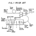
- an active fiber 1 which is an optical amplification fiber, comprises an optical fiber with a dopant being added to a core portion thereof.
- the active fiber can absorb exciting light having specific wavelengths to amplify signal light having wavelengths different from the wavelengths of the exciting light.
- a wavelength multiplexing coupler 2 is provided for efficiently introducing exciting light into the active fiber 1 without causing no significant loss of the signal light.
- Numeral 3 designates an optical isolator for signal light.
- Numeral 4 designates an exciting laser module that generates exciting light for exciting the active fiber 1.
- the exciting laser module 4 comprises an exciting LD (laser diode) device 6 and an optical lens system 7 for efficiently coupling the exciting light output from the exciting LD device 6 to the terminal of an optical fiber 10.
- LD laser diode
- the module 4 further comprises a photodiode 5 for a monitor that monitors output power from the end of the fiber to the exciting LD device 6.
- the reflectance of the outgoing face and the reflectance of the reflecting face in the exciting LD device 6 are respectively R1 and R2. As shown in FIG. 2A, R1 is several %, and R2 about 90%.
- an optical isolator 9 is provided within the exciting laser module is the prevention of such an unfavorable phenomenon that, upon entry of lights into the exciting LD device 6 through the end of the fiber, the state of operation of the exciting LD device 6 is varied rendering the power of the exciting light output unstable.
- Lights which enter the exciting LD device 6 through the terminal of the fiber include exciting light returned as a result of reflection or scattering within the optical amplifier, leaked noise light (ASE: amplified spontaneous emission) generated within the active fiber 1, and leaked amplified signal light.
- the first problem is that, upon a fluctuation in environmental temperature, the optical amplifier cannot be satisfactorily stably operated.
- the reason for this is as follows.
- the fluctuation in environmental temperature brings about a fluctuation in temperature of the exciting laser device. This in turn causes a change in wavelengths of the exciting light output from the exciting laser.
- wavelengths of the exciting light are deviated from the absorption wavelength range of the active fiber, making it impossible for the optical amplifier to perform satisfactorily stable optical amplification operation.
- the exciting light wavelength absorption range for 1480 nm band is relatively broad being from 1450 to 1490 nm, while the exciting light wavelength absorption range for 980 nm band is as narrow as 5 nm. Therefore, when an exciting laser of 980 nm band is used as an excitation source, the exciting laser should not cause a fluctuation in wavelength upon a fluctuation in environmental temperature.
- the temperature is controlled by cooling the exciting laser device by means of a Peltier cooler to keep the temperature of the exciting laser device constant independently of a fluctuation in environmental temperature.
- the Peltier cooler cannot be used because the reliability of the Peltier cooler is low. Therefore, in order to cope with the use of active fibers having a narrow exciting light absorption range, the development of the construction of an optical amplifier capable of realizing both high reliability and stable operation independently of a fluctuation in temperature has been desired in the art.
- an optical amplifier comprises an active fiber, the active fiber comprising an optical fiber with a dopant being added to a core portion thereof, the active fiber being adapted for absorbing exciting light having specific wavelengths to amplify signal light having wavelengths different from the wavelengths of the exciting light,
- the exciting light introduction means preferably comprises: an optical isolator that sends the light output from the wavelength selection type reflection device toward only the active fiber; an optical lens system that permits the input of the light output from the optical isolator; and an introduction optical fiber for introducing the light output from the optical lens system into the active fiber.
- an optical amplifier comprises:
- the wavelength selection type reflection device is preferably set so that the reflectance of the exciting light at the specific wavelengths is 10% to several %.
- the reflecting wavelength band of the specific wavelengths in the wavelength selection type reflection device is not more than 2 nm.
- the active fiber is preferably an erbium-doped fiber.
- the exciting light preferably has wavelengths falling within a band of 975 to 985 nm or a band of 1450 to 1490 nm.
- the signal light in the active fiber has wavelengths falling within a band of 1500 to 1600 nm.
- the wavelength selection type reflection device interposed between the exciting laser device and the optical isolator is designed so as to reflect only light having specific wavelengths that can excite the active fiber with the highest efficiency. Further, setting of the reflectance of the light at the specific wavelengths to about several % for optimization can realize the construction of a laser resonator between the exciting laser device and the wavelength selection type reflection device. In this case, the reflectance on the outgoing surface of the exciting laser device should be satisfactorily lower than the reflectance of the wavelength selection type reflection device.
- the laser resonator between the exciting laser device and the wavelength selection type reflection device is formed only in the above specific wavelengths. Therefore, no laser resonator is formed for light having other wavelengths generated by the exciting laser device. This permits laser oscillation, from the exciting laser module, of only light having specific wavelengths that can excite the active fiber with the highest efficiency.
- the laser oscillation at the same wavelength can be advantageously continued as long as the amplification factor of wavelengths for which a resonator is constructed by the wavelength selection type reflection device is not remarkably lowered. Therefore, the adoption of the above construction can realize the provision of an optical amplifier that, even when the temperature fluctuates, does not cause a fluctuation in wavelengths of the exciting light. Further, in this case, the operation of the optical amplifier per se is stable against the fluctuation in temperature.
- FIG. 3 is a diagram showing an optical amplifier according to a preferred embodiment of the invention.
- the optical amplifier shown in FIG. 3 is different from the optical amplifier shown in FIG. 1 in that, in FIG. 3, within the exciting laser module, a wavelength selection type reflection device 8 is interposed between the exciting LD device 6 and the optical isolator 9.
- This wavelength selection type reflection device 8 reflects, among wavelengths of exciting light emitted from the exciting LD device 6, only specific wavelengths capable of exciting the active fiber 1 with the highest efficiency and returns them to the exciting LD device 6.
- the optical isolator 3 inserted into an output port of the signal light prevents signal light output from the optical amplifier being reflected from the transmission path and returned to within the active fiber 1. This can realize stable operation of the optical amplifier without being influenced by reflected return light from the outside thereof.
- an optical isolator is inserted into only the output port.
- the optical isolator may also be inserted into an input port for the same purpose.
- the active fiber 1 is designed as follows.
- the exciting light input through the wavelength multiplexing coupler 2 is absorbed, and the signal light is amplified by stimulated emission utilizing the stored energy.
- the exciting laser module 4 constructs a laser resonator between the wavelength selection type reflection device 8, interposed between the exciting LD device 6 and the optical isolator 9, and the backside of the exciting LD device 6, permitting laser to be forcibly oscillated at specified wavelengths.
- FIGs. 2A to 2E are graphs showing characteristics relative to wavelengths in the conventional optical amplifier, and FIGs. 4A to 4E graphs showing characteristics relative to wavelengths in an optical amplifier according to a preferred embodiment of the invention.
- the abscissa represents the wavelength.
- the backward reflectance R2 of the exciting LD resonator represents the reflectance of the backside of the exciting LD device 6.
- the forward reflectance R1 of the exciting LD resonator represents the front reflectance of the exciting LD device 6 in the case of the conventional optical amplifier and represents the reflectance of the wavelength selection type reflection device 8 in the case of the optical amplifier of the preferred embodiment of the invention.
- the forward reflectance R1 is a reflectance (10 to several %) which is uniform independently of the wavelength.
- the forward reflectance in the case of the optical amplifier according to the preferred embodiment of the invention is such that the reflectance is several % for only specific wavelengths, while the reflectance for the other wavelengths is limited to a low value. Therefore, laser oscillation conditions are satisfied at only specific wavelengths for which the reflectance of the exciting laser module wavelength selection type reflection device is several %.
- the gain G of the exciting LD device is shifted toward the wavelength (FIG. 2B).
- the laser oscillation wavelength also varies (FIG. 2D).
- FIG. 2E is a graph showing the relationship between the wavelengths of exciting light and the exciting light absorption coefficient of the active fiber for the conventional optical amplifier
- FIG. 4B is a graph showing the relationship between the wavelengths of exciting light and the exciting light absorption coefficient of the active fiber for the optical amplifier of the embodiment.
- the wavelengths of the exciting light are shifted with the temperature change and deviated from the absorption wavelength band of the active fiber.
- the exciting light wavelengths are stable against the temperature change and always conform to the absorption wavelength band of the active fiber.
- a high-output LD module of 1480 nm band (1450 to 1490 nm) or 980 nm band (975 to 985 nm) is used as the exciting light source.
- the absorption wavelength band of the active fiber is as narrow as 5 nm, and, hence, the exciting light wavelength stabilizing technique of the invention is particularly important.
- optical devices such as optical band reflection filters (notch filters) of a narrow band or diffraction gratings
- the reflection bandwidth of the wavelength selection type reflection device is brought to not more than 2 nm to realize a mode-locked operation at a narrow line width.
- the reflectance of the wavelength selection type reflection device is brought to about several %, and the operation of exciting laser at a high output with high stability can be expected by optimization.
- a wavelength selection type reflection device is provided within an exciting LD laser module to remain laser oscillation wavelengths unchanged independently of the temperature change. Therefore, the operation of the optical amplifier is advantageously stable against a change in environment.
- any device having low reliability such as a Peltier cooler, is not used for the stabilization of the exciting light wavelengths. Therefore, the optical amplifier according to the invention is best suited also for applications where high reliability is required, such as submarine repeaters.
Landscapes
- Physics & Mathematics (AREA)
- Electromagnetism (AREA)
- Engineering & Computer Science (AREA)
- Plasma & Fusion (AREA)
- Optics & Photonics (AREA)
- Lasers (AREA)
- Optical Communication System (AREA)
Applications Claiming Priority (2)
| Application Number | Priority Date | Filing Date | Title |
|---|---|---|---|
| JP35593097 | 1997-12-25 | ||
| JP35593097A JPH11186642A (ja) | 1997-12-25 | 1997-12-25 | 光増幅器 |
Publications (2)
| Publication Number | Publication Date |
|---|---|
| EP0944141A2 true EP0944141A2 (fr) | 1999-09-22 |
| EP0944141A3 EP0944141A3 (fr) | 2001-03-07 |
Family
ID=18446471
Family Applications (1)
| Application Number | Title | Priority Date | Filing Date |
|---|---|---|---|
| EP98310760A Withdrawn EP0944141A3 (fr) | 1997-12-25 | 1998-12-24 | Amplificateur optique |
Country Status (2)
| Country | Link |
|---|---|
| EP (1) | EP0944141A3 (fr) |
| JP (1) | JPH11186642A (fr) |
Cited By (1)
| Publication number | Priority date | Publication date | Assignee | Title |
|---|---|---|---|---|
| EP1209783A3 (fr) * | 2000-11-02 | 2004-06-30 | The Furukawa Electric Co., Ltd. | Module laser à semiconducteur et amplificateur raman |
Families Citing this family (4)
| Publication number | Priority date | Publication date | Assignee | Title |
|---|---|---|---|---|
| WO2001089045A1 (fr) * | 2000-05-19 | 2001-11-22 | Mitsubishi Cable Industries, Ltd. | Amplificateur a fibre dopee a un element des terres rares et a sources lumineuses de pompage, et amplificateur raman |
| JP2009059938A (ja) * | 2007-08-31 | 2009-03-19 | Nippon Telegr & Teleph Corp <Ntt> | 光ファイバ増幅器 |
| JP2013120799A (ja) * | 2011-12-06 | 2013-06-17 | Mitsubishi Electric Corp | レーザ装置 |
| JP2012080138A (ja) * | 2012-01-24 | 2012-04-19 | Nippon Telegr & Teleph Corp <Ntt> | 光ファイバ増幅器 |
Family Cites Families (1)
| Publication number | Priority date | Publication date | Assignee | Title |
|---|---|---|---|---|
| JPH09148660A (ja) * | 1995-11-24 | 1997-06-06 | Mitsubishi Electric Corp | 半導体レーザ装置および光増幅装置 |
-
1997
- 1997-12-25 JP JP35593097A patent/JPH11186642A/ja active Pending
-
1998
- 1998-12-24 EP EP98310760A patent/EP0944141A3/fr not_active Withdrawn
Cited By (1)
| Publication number | Priority date | Publication date | Assignee | Title |
|---|---|---|---|---|
| EP1209783A3 (fr) * | 2000-11-02 | 2004-06-30 | The Furukawa Electric Co., Ltd. | Module laser à semiconducteur et amplificateur raman |
Also Published As
| Publication number | Publication date |
|---|---|
| JPH11186642A (ja) | 1999-07-09 |
| EP0944141A3 (fr) | 2001-03-07 |
Similar Documents
| Publication | Publication Date | Title |
|---|---|---|
| US6950452B2 (en) | Semiconductor laser module and method for simultaneously reducing relative intensity noise (RIN) and stimulated brillouin scattering (SBS) | |
| US5555127A (en) | Planar hybrid optical amplifier | |
| EP0717478B1 (fr) | Amplificateur optique | |
| EP1209783A2 (fr) | Module laser à semiconducteur et amplificateur raman | |
| GB2340297A (en) | Long-wavelength optical fibre amplifier | |
| US20020118715A1 (en) | Semiconductor laser module and Raman amplifier using the module | |
| US20090147350A1 (en) | Amplified spontaneous emission reflector-based gain-clamped fiber amplifier | |
| US20210281036A1 (en) | Broadband tm-doped optical fiber amplifier | |
| KR100415548B1 (ko) | 2단 장파장 대역 어븀첨가 광섬유 증폭 장치 | |
| CA2042697C (fr) | Amplificateur a fibres optiques | |
| GB2306245A (en) | Optical fibre amplifier | |
| US20020093998A1 (en) | Semiconductor laser module and amplifier using the module | |
| EP0944141A2 (fr) | Amplificateur optique | |
| KR100334809B1 (ko) | 씨드-빔을 이용한 광대역 광원 | |
| JP4848836B2 (ja) | 光活性デバイス | |
| KR20040106676A (ko) | 라만 증폭원리를 이용한 이득 고정 반도체 광증폭기 | |
| US6178039B1 (en) | Light source module and an optical amplifier using the same | |
| US7038840B1 (en) | Discrete Raman fiber oscillator | |
| US20020089738A1 (en) | Optical fiber amplifier and method of amplifying an optical signal | |
| JP2002252399A (ja) | 光増幅器 | |
| JP2713395B2 (ja) | 光ファイバ増幅器および光ファイバ伝送装置 | |
| JP3690110B2 (ja) | 光増幅器およびレーザ発振器 | |
| JP3273911B2 (ja) | 光ファイバ増幅器、励起用半導体レーザモジュールおよび光信号伝送システム | |
| WO2002079851A1 (fr) | Amplificateur a fibre dopee a l'erbium et a gain fixe destine a la bande des ondes longues | |
| JP3250473B2 (ja) | 光増幅器 |
Legal Events
| Date | Code | Title | Description |
|---|---|---|---|
| PUAI | Public reference made under article 153(3) epc to a published international application that has entered the european phase |
Free format text: ORIGINAL CODE: 0009012 |
|
| AK | Designated contracting states |
Kind code of ref document: A2 Designated state(s): FR GB |
|
| AX | Request for extension of the european patent |
Free format text: AL;LT;LV;MK;RO;SI |
|
| PUAL | Search report despatched |
Free format text: ORIGINAL CODE: 0009013 |
|
| AK | Designated contracting states |
Kind code of ref document: A3 Designated state(s): AT BE CH CY DE DK ES FI FR GB GR IE IT LI LU MC NL PT SE |
|
| AX | Request for extension of the european patent |
Free format text: AL;LT;LV;MK;RO;SI |
|
| RIC1 | Information provided on ipc code assigned before grant |
Free format text: 7H 01S 3/06 A, 7H 01S 3/0941 B |
|
| 17P | Request for examination filed |
Effective date: 20010316 |
|
| AKX | Designation fees paid |
Free format text: FR |
|
| RBV | Designated contracting states (corrected) |
Designated state(s): FR GB |
|
| REG | Reference to a national code |
Ref country code: DE Ref legal event code: 8566 |
|
| STAA | Information on the status of an ep patent application or granted ep patent |
Free format text: STATUS: THE APPLICATION HAS BEEN WITHDRAWN |
|
| 18W | Application withdrawn |
Withdrawal date: 20020802 |