EP0948074A2 - Batterie secondaire et procédé de fabrication - Google Patents
Batterie secondaire et procédé de fabrication Download PDFInfo
- Publication number
- EP0948074A2 EP0948074A2 EP99106592A EP99106592A EP0948074A2 EP 0948074 A2 EP0948074 A2 EP 0948074A2 EP 99106592 A EP99106592 A EP 99106592A EP 99106592 A EP99106592 A EP 99106592A EP 0948074 A2 EP0948074 A2 EP 0948074A2
- Authority
- EP
- European Patent Office
- Prior art keywords
- secondary battery
- conductive member
- polymer
- ion conductive
- positive electrode
- Prior art date
- Legal status (The legal status is an assumption and is not a legal conclusion. Google has not performed a legal analysis and makes no representation as to the accuracy of the status listed.)
- Withdrawn
Links
Images


Classifications
-
- H—ELECTRICITY
- H01—ELECTRIC ELEMENTS
- H01M—PROCESSES OR MEANS, e.g. BATTERIES, FOR THE DIRECT CONVERSION OF CHEMICAL ENERGY INTO ELECTRICAL ENERGY
- H01M10/00—Secondary cells; Manufacture thereof
- H01M10/05—Accumulators with non-aqueous electrolyte
- H01M10/056—Accumulators with non-aqueous electrolyte characterised by the materials used as electrolytes, e.g. mixed inorganic/organic electrolytes
- H01M10/0564—Accumulators with non-aqueous electrolyte characterised by the materials used as electrolytes, e.g. mixed inorganic/organic electrolytes the electrolyte being constituted of organic materials only
- H01M10/0566—Liquid materials
- H01M10/0569—Liquid materials characterised by the solvents
-
- H—ELECTRICITY
- H01—ELECTRIC ELEMENTS
- H01M—PROCESSES OR MEANS, e.g. BATTERIES, FOR THE DIRECT CONVERSION OF CHEMICAL ENERGY INTO ELECTRICAL ENERGY
- H01M10/00—Secondary cells; Manufacture thereof
- H01M10/36—Accumulators not provided for in groups H01M10/05-H01M10/34
- H01M10/38—Construction or manufacture
-
- H—ELECTRICITY
- H01—ELECTRIC ELEMENTS
- H01M—PROCESSES OR MEANS, e.g. BATTERIES, FOR THE DIRECT CONVERSION OF CHEMICAL ENERGY INTO ELECTRICAL ENERGY
- H01M10/00—Secondary cells; Manufacture thereof
- H01M10/05—Accumulators with non-aqueous electrolyte
- H01M10/052—Li-accumulators
-
- H—ELECTRICITY
- H01—ELECTRIC ELEMENTS
- H01M—PROCESSES OR MEANS, e.g. BATTERIES, FOR THE DIRECT CONVERSION OF CHEMICAL ENERGY INTO ELECTRICAL ENERGY
- H01M10/00—Secondary cells; Manufacture thereof
- H01M10/05—Accumulators with non-aqueous electrolyte
- H01M10/056—Accumulators with non-aqueous electrolyte characterised by the materials used as electrolytes, e.g. mixed inorganic/organic electrolytes
- H01M10/0564—Accumulators with non-aqueous electrolyte characterised by the materials used as electrolytes, e.g. mixed inorganic/organic electrolytes the electrolyte being constituted of organic materials only
- H01M10/0565—Polymeric materials, e.g. gel-type or solid-type
-
- H—ELECTRICITY
- H01—ELECTRIC ELEMENTS
- H01M—PROCESSES OR MEANS, e.g. BATTERIES, FOR THE DIRECT CONVERSION OF CHEMICAL ENERGY INTO ELECTRICAL ENERGY
- H01M10/00—Secondary cells; Manufacture thereof
- H01M10/24—Alkaline accumulators
-
- H—ELECTRICITY
- H01—ELECTRIC ELEMENTS
- H01M—PROCESSES OR MEANS, e.g. BATTERIES, FOR THE DIRECT CONVERSION OF CHEMICAL ENERGY INTO ELECTRICAL ENERGY
- H01M10/00—Secondary cells; Manufacture thereof
- H01M10/24—Alkaline accumulators
- H01M10/26—Selection of materials as electrolytes
-
- H—ELECTRICITY
- H01—ELECTRIC ELEMENTS
- H01M—PROCESSES OR MEANS, e.g. BATTERIES, FOR THE DIRECT CONVERSION OF CHEMICAL ENERGY INTO ELECTRICAL ENERGY
- H01M50/00—Constructional details or processes of manufacture of the non-active parts of electrochemical cells other than fuel cells, e.g. hybrid cells
- H01M50/40—Separators; Membranes; Diaphragms; Spacing elements inside cells
- H01M50/409—Separators, membranes or diaphragms characterised by the material
- H01M50/411—Organic material
- H01M50/414—Synthetic resins, e.g. thermoplastics or thermosetting resins
-
- H—ELECTRICITY
- H01—ELECTRIC ELEMENTS
- H01M—PROCESSES OR MEANS, e.g. BATTERIES, FOR THE DIRECT CONVERSION OF CHEMICAL ENERGY INTO ELECTRICAL ENERGY
- H01M50/00—Constructional details or processes of manufacture of the non-active parts of electrochemical cells other than fuel cells, e.g. hybrid cells
- H01M50/40—Separators; Membranes; Diaphragms; Spacing elements inside cells
- H01M50/409—Separators, membranes or diaphragms characterised by the material
- H01M50/411—Organic material
- H01M50/429—Natural polymers
-
- Y—GENERAL TAGGING OF NEW TECHNOLOGICAL DEVELOPMENTS; GENERAL TAGGING OF CROSS-SECTIONAL TECHNOLOGIES SPANNING OVER SEVERAL SECTIONS OF THE IPC; TECHNICAL SUBJECTS COVERED BY FORMER USPC CROSS-REFERENCE ART COLLECTIONS [XRACs] AND DIGESTS
- Y02—TECHNOLOGIES OR APPLICATIONS FOR MITIGATION OR ADAPTATION AGAINST CLIMATE CHANGE
- Y02E—REDUCTION OF GREENHOUSE GAS [GHG] EMISSIONS, RELATED TO ENERGY GENERATION, TRANSMISSION OR DISTRIBUTION
- Y02E60/00—Enabling technologies; Technologies with a potential or indirect contribution to GHG emissions mitigation
- Y02E60/10—Energy storage using batteries
-
- Y—GENERAL TAGGING OF NEW TECHNOLOGICAL DEVELOPMENTS; GENERAL TAGGING OF CROSS-SECTIONAL TECHNOLOGIES SPANNING OVER SEVERAL SECTIONS OF THE IPC; TECHNICAL SUBJECTS COVERED BY FORMER USPC CROSS-REFERENCE ART COLLECTIONS [XRACs] AND DIGESTS
- Y02—TECHNOLOGIES OR APPLICATIONS FOR MITIGATION OR ADAPTATION AGAINST CLIMATE CHANGE
- Y02P—CLIMATE CHANGE MITIGATION TECHNOLOGIES IN THE PRODUCTION OR PROCESSING OF GOODS
- Y02P70/00—Climate change mitigation technologies in the production process for final industrial or consumer products
- Y02P70/50—Manufacturing or production processes characterised by the final manufactured product
-
- Y—GENERAL TAGGING OF NEW TECHNOLOGICAL DEVELOPMENTS; GENERAL TAGGING OF CROSS-SECTIONAL TECHNOLOGIES SPANNING OVER SEVERAL SECTIONS OF THE IPC; TECHNICAL SUBJECTS COVERED BY FORMER USPC CROSS-REFERENCE ART COLLECTIONS [XRACs] AND DIGESTS
- Y02—TECHNOLOGIES OR APPLICATIONS FOR MITIGATION OR ADAPTATION AGAINST CLIMATE CHANGE
- Y02T—CLIMATE CHANGE MITIGATION TECHNOLOGIES RELATED TO TRANSPORTATION
- Y02T10/00—Road transport of goods or passengers
- Y02T10/60—Other road transportation technologies with climate change mitigation effect
- Y02T10/70—Energy storage systems for electromobility, e.g. batteries
Definitions
- the present invention relates to a secondary battery having an ion conductive member, and a manufacturing process thereof. More particularly, it relates to a secondary battery in which the decomposition of an electrolyte solution attributed to the repetition of charge and discharge is suppressed.
- the carbonaceous material as a host material which is intercalated between the layers by using lithium as a guest is applied to the negative electrode, thereby to suppress the growth of the dendrite of lithium during charge and to achieve a longer lifetime in change-and-discharge cycles.
- an organic solvent is used as the solvent of an electrolyte solution in the secondary battery utilizing galvanic reactions (charge-and-discharge reactions) based on lithium ions, such as the lithium-ion secondary battery. Therefore, when the battery is overcharged, the solvent is decomposed to produce carbonic acid gas, hydrocarbon etc., and it is not restored to its original state by a recombination reaction. It is accordingly apprehended that the electrolyte solution will deteriorate to increase the internal impedance of the secondary battery. Further, the overcharge of the secondary battery incurs the internal short-circuit thereof to generate heat and to promote a reaction rapidly decomposing the solvent, which can lead even to the breakage of the battery.
- the present invention has been made in view of the problems stated above, and it has for its object to provide an electrolyte for use in a secondary battery, which is immune against deterioration and decomposition in the charge-and-discharge reactions of the secondary battery, and a novel secondary battery which employs the electrolyte.
- the first mode of the present invention consists in a secondary battery wherein an ion conductive member is arranged between a positive electrode and a negative electrode which are disposed in opposition to each other, characterized in that said ion conductive member has its ion channels oriented so as to have a higher ionic conductivity in a direction of joining a plane of said positive electrode and that of said negative electrode.
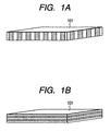
- the secondary battery shall cover a contrivance wherein said ion conductive member has a layered structure or a columnar structure.
- the cross-linked polymer material having the layered or columnar structure can be obtained in such a way that the molecules of a cross-linking polymer are arrayed into a regular arrangement by at least one operation selected from the group consisting of irradiation with light, the application of a magnetic field, the application of an electric field, and heating, whereupon the resulting molecules are cross-linked.
- the polymer of the specified structure can be obtained in such a way that a compound which has a molecular structure serving as a template is employed in the operation of preparing the cross-linked polymer.
- 1B which should preferably have a thickness of 500 ⁇ m or below, more preferably a thickness of 100 ⁇ m or below, and the ionic conductivity of which is higher in a direction perpendicular to the planes of a negative electrode and a positive electrode, may be sandwiched between the negative and positive electrodes which oppose to each other.
- the ion conductive member having the layered structure or columnar structure can be fabricated by preparing a cross-linked polymer which has the layered or columnar structure and which absorbs an electrolyte solution (a solution obtained by dissolving a supporting electrolyte in a solvent).
- an electrolyte solution a solution obtained by dissolving a supporting electrolyte in a solvent.
- the layered or columnar structure of the cross-linked polymer can be attained in such a way that molecules constituting a cross-linking polymer are arrayed into a regular arrangement by at least one operation selected from the group consisting of irradiation with light, the application of a magnetic field, the application of an electric field, and heating, or that molecules constituting a cross-linking polymer are arrayed using a template.
- the ion conductive member having the layered structure or columnar structure can be formed in such a way that, under the application of an electric field and/or a magnetic field, an inorganic oxide such as ionically conductive glass is vapordeposited with a cluster ion beam or electron beam or by sputtering.
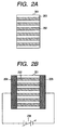
- Fig. 2A is a schematic view showing the ion conductive member 201.
- ion conducting paths (ion channels) 202 being the shortest are so formed that they are arrayed, namely, oriented in a direction parallel to the layered or columnar structure or in a direction perpendicular to the layered structure.
- ion conducting paths (ion channels) 202 being the shortest are so formed that they are arrayed, namely, oriented in a direction parallel to the layered or columnar structure or in a direction perpendicular to the layered structure.
- the ion conductive member 201 in which the direction of the shortest ion-conducting paths (ion channels) 202 agrees with a direction perpendicular to the planes of electrodes 204 and 205, is arranged between the electrodes 204 and 205, and these electrodes 204 and 205 are connected to a supply voltage source 206.
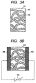
- ion conducting paths (ion channels) 302 are formed in random directions within the matrix 303 of the structure 301.
- the ion conductive member 301 is arranged between electrodes 304 and 305, which are connected to a supply voltage source 306.
- the channel length of the former 201 in the direction in which the ion channels 202 are oriented is substantially shorter than that of the latter 301.
- an electric field is applied across the ion conductive members 201 and 301 (between the electrodes 204 and 205, and between the electrodes 304 and 305) so as to cause the ions to migrate in the directions in which the ion channels 202 and 302 are oriented, an electric field intensity (applied voltage/channel length) becomes higher to afford a higher migrating ionic velocity ((mobility of ions) ⁇ (electric field intensity)), in the ion conductive member 201 of the shorter ion channels corresponding to the present invention.
- the ion conductive member 201 since the ionic conductivity of each structure at issue enlarges in proportion to the concentration of the ions and the migrating velocity thereof, the ion conductive member 201 exhibits a higher ionic conductivity. Besides, in the ion conductive member 201 shown in Figs. 2A and 2B, the shortest ion channels are arrayed in the direction perpendicular to the planes of the opposing electrodes, and the ionic conductivity in this direction is selectively higher than in any other direction. Therefore, the ion conductive member 201 exhibits an anisotropy in ion conduction.
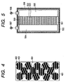
- Fig. 4 illustrates another aspect of the ion conductive member of the present invention.
- the ion conductive member 401 shown in the figure is an aggregate including a large number of granular ionic-conduction elements 402 in each of which ion channels are regularly arranged along a layered or columnar structure 403. Since the shortest ion channels arranged regularly in a certain direction are formed in each granular ionic-conduction element 402, a substantially higher ionic conductivity is attained as all the granular ionic-conduction elements 402.
- numeral 404 designates a layer (material) which binds up the granular ionic-conduction elements 402.
- An organic polymer gel, a granular inorganic-oxide gel (for example, granular silica gel), or the like can be employed for the granular ionic-conduction elements 402.
- the granular ionic-conduction elements 402 can be worked into the shape of a layer or film or a sheet by using a polyethylene oxide or the like resin as a binder.
- these elements 402 can be processed into the shape of a film or sheet by a processing method such as calendering.
- Fig. 5 illustrates the general configuration of the secondary battery of the present invention.
- a secondary battery 500 is a square battery whose section in a direction normal to the drawing sheet is rectangular.
- Terminals 507 and 508 for external connection are respectively connected to the negative electrode 504 and the positive electrode 505, and they are connected to an external load or a power source.
- the ion conductive member 501 employed has its ion channels 502 oriented along a layered or columnar structure in the direction perpendicular to the planes of the opposing negative electrode 504 and positive electrode 505. Accordingly, the migrating distances of ions between the negative electrode 504 and the positive electrode 505 become the shortest, and the substantial migrating velocity thereof heightens, so that the impedance of the secondary battery is lower. It is therefore possible to realize the secondary battery which can be charged and discharged at higher current densities, and which has a higher charge-and-discharge efficiency.
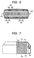
- Fig. 6 illustrates a practicable configuration in which the secondary battery of the present invention is applied to a sheetlike battery.
- an ion conductive member 601 is sandwiched as a separator between a negative electrode 604 including an active material layer 605 on a collector 606 and a positive electrode 607 including an active material layer 608 on a collector 609.
- the ion conductive member 601 has the shortest ion channels 602 which are formed along a layered or columnar structure and which are arrayed in a direction perpendicular to the opposing negative electrode 604 and positive electrode 607 within the matrix 603 of the ion conductive member as shown in Fig. 1A, Fig. 1B or Fig.
- the matrix 603 being oriented in a direction perpendicular to the planes of the positive and negative electrodes and being filled with an electrolyte therein.
- the resulting laminated body of the "negative electrode/ion conductive member/positive electrode” has input/output terminals (not shown) led out of the collectors of the respective electrodes and is covered with a sheathing material 610.
- Such a secondary battery 600 is charged by connecting an unshown external power source to the input/output terminals, and it accumulates electricity owing to electrochemical reactions (the migrations of ions between the electrodes) which arise through the ion conductive member 601. Besides, when an unshown external load is connected to the input/output terminals, electrochemical reactions (the migrations of ions between the electrodes) arise through the ion conductive member 601 inside the battery, and the battery is discharged.
- the characteristics of the ion conductive member 601 incarnate the shortest migrating distances of ions between the negative electrode 604 and the positive electrode 607 and heighten the substantial migrating velocity of the ions. It is therefore possible to realize the secondary battery whose internal resistance is lower, which can be charged and discharged at higher current densities, and which has a higher charge-and-discharge efficiency.
- the ion conductive member 601 sandwiched between the electrodes is a solid structure or a solidified structure.
- the sheetlike battery undergoes no liquid leakage even in case of the damage of the sheathing material 610, and the decomposition of a solvent in the electrolyte on the occasion of overcharge is suppressed. Therefore, a safety mechanism such as safety valve is dispensed with, the thickness of the battery can be decreased, and an overcharge circuit having been complicated can be replaced with a simple circuit.
- the sheetlike battery can have its shape designed at will, and it can minimize the installation space of a power source in the application thereof to the power source of an apparatus.
- the single pair of electrodes; the positive electrode 607 and the negative electrode 604 are included in the aspect of the sheetlike battery shown in Fig. 6. It is also possible, however, to construct a secondary battery in a configuration in which a plurality of pairs of electrodes are disposed to form a laminated body consisting of, for example, the "negative electrode/ion conductive member/positive electrode/ion conductive member/negative electrode/ion conductive member/positive electrode", and in which cell units each consisting of the "negative electrode/ion conductive member/positive electrode” are connected in parallel or in series inside the laminated body.
- the cell units each consisting of the "negative electrode/ion conductive member/positive electrode” are assembled into the battery housing of a battery in a shape as will be stated later, such as a coin-shaped battery, a cylindrical battery or a square battery.
- the ion conductive member for use in the secondary battery of the present invention can have a layered structure or a columnar structure.
- ion conducting paths (ion channels) along which the migrating distances of ions become substantially the shortest are formed in a direction parallel to the layered or columnar structure or in a direction perpendicular to the layered structure. Therefore, the ionic conductivity of the ion conductive member becomes the highest in the paths, and the ion conductive member exhibits an anisotropic conductivity.
- the secondary battery of the present invention can be constructed in such a way that the ion conductive member, which has the layered structure or columnar structure and whose ionic conductivity is higher in a direction perpendicular to the planes of a negative electrode and a positive electrode opposing to each other, is sandwiched between the negative electrode and the positive electrode.
- the material of the ion conductive member having the layered structure or columnar structure for use in the present invention may be any of, for example, an organic or inorganic gelatinous polymer and an ionically conductive glass each of which is endowed with a specified molecular orientation.
- the glass transition temperature of the ion conductive member for use in the secondary battery of the present invention should preferably be minus 20°C or below, more preferably be minus 30°C or below, much more preferably be minus 50°C or below.
- the glass transition temperature can be found by the thermal analysis of a measurement based on a compressive load method employing a thermomechanical analyzer, a measurement employing a differential scanning calorimeter, or the like.
- a process for preparing a cross-linked polymer of layered structure or columnar structure to serve as the matrix of a polymer gel electrolyte which is an ion conductive member with oriented ion channels is divided into a process in which a monomer is polymerized and cross-linked (the process of the above example (a)), and a process in which a polymer is cross-linked (the process of the above example (b)).
- the addition polymerization is divided into radical polymerization, and ionic polymerization such as cationic polymerization and anionic polymerization in accordance with reaction mechanisms.
- an initiator is employed which is decomposed to generate radicals by heating or the absorption of light such as ultraviolet rays, thereby to initiate the polymerizing reaction of the monomer.
- the initiator are azo compound such as azo-bis-isobutylonitrile; a peroxide such as benzoyl peroxide; potassium persulfate; ammonium persulfate; and the light-absorption decomposition compound of a ketonic compound or metallocenic compound.
- Examples of the initiator of the cation polymerization include an acid such as H 2 SO 4 , H 3 PO 4 , HClO 4 or CCl 3 CO 2 H; a Friedel-Crafts catalyst such as BF 3 , AlCl 3 , TiCl 4 or SnCl 4 ; I 2 ; and (C 6 H 5 ) 3 CCl.
- Examples of the initiator of the anion polymerization include water, an alkaline metal compound, and a magnesium compound.
- the quantity of addition of the initiator to the monomer a range of 1 to 10 weight-% is preferable, and a range of 2 to 5 weight-% is more preferable.
- Typical of the monomer to be addition-polymerized is a vinyl compound.
- the vinyl compound are diethyleneglycol ethylether acrylate, diethyleneglycol ethylether methacrylate, diethyleneglycol methylether methacrylate, diethyleneglycol 2-ethylhexylether acrylate, diethylethoxymethylene malonate, 2-acetoxy-3-butenenitrile, allylcyano acetate, 4-allyl-1,2-dimethoxybenzene, acrylonitrile, methyl acrylate, methyl methacrylate, vinyl acetate, ethylene, isoprene, butadiene, styrene, vinyl chloride, vinylidene chloride, isobutyrene, ⁇ -methyl styrene, tetradecane diol acrylate, silicone metharylate, fluoroalkyl methacrylate, 2-hydroxyethyl methacrylate
- the monomers should desirably be selected in order that the glass transition temperature of the polymer obtained by the polymerization may preferably become minus 20°C or below, more preferably minus 30°C or below.
- liquid-crystalline monomer whose molecules are regularly arrayed by the application of an electric field or a magnetic field or irradiation with light.
- concrete examples of a polymer material which serves as a base in a process for preparing a cross-linked polymer by cross-linking the polymer material already obtained are poly(N-iso-propyl acrylamide), poly(methylvinyl ether), poly(N-vinyliden butylamide, the polymer of vinyl ether, poly( ⁇ -benzyl L-glutamate), poly(p-phenylene terephthalamide), polycarbonate, poly(methyl methacrylate), acrylonitrile-butadiene rubber, poly(diisopropyl fumarate), and polyvinylidene fluoride.
- a polymer gel electrolyte which includes a cross-linked polymer and an electrolyte solution absorbed in the cross-linked polymer, is prepared using the polymer material produced by the polymerizing reaction or the already polymerized material as stated above.
- a process for preparing the cross-linked polymer (polymer gel) is divided into a process based on chemical bonding, and a process based on intermolecular bonding.
- the process based on the chemical bonding includes a process in which the polymer is irradiated with an energy radiation such as an electron beam or gamma rays, so as to generate radicals and to induce a cross-linking reaction, and a process in which some active groups of a polymer chain are reacted with a cross-linking agent so as to induce a cross-linking reaction.
- an energy radiation such as an electron beam or gamma rays
- a process in which the active groups of the side chain of a polymer and a polyfunctional cross-linking agent are reacted for the cross-linkage can be suitably adopted as the process in which the cross-linking reaction is induced by reacting some active groups of the polymer chain with the cross-linking agent.
- Concrete examples are cross-linking processes which are based on the reaction between the ester bonds or carboxyl groups of the side chain and a diamine compound, the reaction between the amino groups of the side chain and dicarbonic acid, the reaction between the carboxyl groups of the side chain and glycols, and the reaction between the hydroxyl groups of the side chain and dicarbonic acid.
- Mentioned as the concrete examples of the above amine are triethylene tetramine, tetramethylethylene diamine, diaminooligoethylene amine, and diaminooligoethylene glycol.
- the proportion of addition thereof should preferably be within a range of 1 to 20 mol-%, more preferably within a range of 2 to 10 mol-%, relative to 1 mol of the polymer.
- Concrete examples include polymerization for which ethyleneglycol dimethacrylate or methylene-bis-acryl amide is compounded as a cross-linking agent, and for which a radical initiator is used; radiation polymerization for which gamma rays or an electron beam are/is projected; and photo-polymerization for which light at a wavelength agreeing with the absorption wavelength of a vinyl monomer is projected in the presence of a cross-linking agent, or for which light is projected after adding a photosensitizer.
- Examples of a divinyl compound typical of a bifunctional monomer which functions as a cross-linking agent during addition polymerization include N, N'-methylene-bis-acryl amide; diethyleneglycol dimethacrylate; diethyleneglycol-bis-allyl carbonate; diethyleneglycol diacrylate; tetraethyleneglycol dimethacrylate; 1, 4-butanediol diacrylate; pentadecanediol diacrylate; allyl ether; and allyl disulfide; 3-acryloyloxy-2-hydroxypropyl methacrylate.
- the quantity of addition of the cross-linking agent for the preparation of the cross-linked polymer (polymer gel) should preferably be within a range of 0.1 to 30 mol-%, more preferably within a range of 1 to 20 mol-%, much more preferably within a range of 2 to 10 mol-%, relative to 1 mol of the monomer.
- the cross-linked polymer which is produced via the polymerizing reaction and the cross-linking reaction, should desirably have at least one sort of bond selected from the group consisting of a carbon-oxygen bond, a carbon-nitrogen bond and a carbon-sulfur bond, in order that when the polymer is caused to carry an electrolyte solution, the ionic dissociation of an electrolyte may be promoted to attain a higher ionic conductivity.
- the cross-linked polymer should preferably include at least one sort of functional group which is selected from the group consisting of an ether group, an ester group, a carbonyl group and an amide group.
- the starting materials of the cross-linked polymer are selected so as to establish such a chemical structure.
- the compound which has a molecular structure serving as a template and which is employed in the preparation of a cross-linked polymer (polymer gel) having a layered structure or columnar structure is a compound which is oriented in a certain direction or whose molecules are regularly arrayed, in accordance with an electric field, a magnetic field, light, a temperature, a concentration, a pressure, a material to touch with the compound or the surface profile of the material, and the combination of such factors.
- a monomer is polymerized and cross-linked, or a polymer is cross-linked, whereby the cross-linked polymer (polymer gel) having the layered structure or columnar structure can be prepared, and an ion conductive member whose matrix is the cross-linked polymer (polymer gel) can be formed.
- the compound which has the molecular structure serving as the template should preferably be at least one sort of compound selected from the group consisting of a liquid-crystalline compound, a diacetylene compound and an amphiphilic compound.
- the above terminal group should preferably be a group which is selected from among, for example, chemical formulas C n H 2n+1 -, C n H 2n+1 O- and CN-.
- the flat liquid-crystalline compound examples include a benzene-ring compound, a heterocyclic compound, and a polycyclic compound. It is also desirable that the molecules of the flat liquid crystal are in a columnar arrayal.
- Examples of a low-molecular cholestic liquid crystal include cholesteryl-nonanate; hexalkanoyl oxybenzene; tetraalkanoyl oxy-p-benzoquinone; hexalkoxy triphenylene; hexalkanoyl oxytriphenylene; hexalkanoyl oxytoluxen; hexalkanoyl rufigallol; 2, 2', 6, 6'-tetraryl-4, 4'-bipyranilidene; 2, 2', 6, 6'-tetraryl-4, 4'-bithiopyranilidene; and the substituted benzoate of hexahydrotriphenylene.
- a low-molecular discotic liquid crystal is triphenylene-hexa-n-dodecanonate, or the like.
- a high-molecular liquid crystal Mentioned as examples of a high-molecular liquid crystal are poly- ⁇ -benzyl-L-glutamate, poly(4-cyanophenyl 4'-hexyloxy benzoate methylsiloxane), poly(4-methoxyphenyl 4'-propyloxy benzoate methylsiloxane), the block copolymer of polystyrene-polyethylene oxide, hydroxypropyl cellulose, poly(p-phenylene terephthalamide), poly[(ethylene terephthalate)-co-1, 4-benzoate], poly(4, 4'-dimethylazoxybenzene dodecanediol), poly(oligoethylene azoxybenzoate), and poly(p-benzamide).
- Each of these liquid-crystal materials can be oriented in a predetermined direction by applying an electric field or magnetic field to the material or irradiating the material with light in a predetermined direction, by selecting the temperature zone of the material or the concentration thereof in a solvent, or by arranging the material on the surface of a base member which has been treated so as to preferentially endow the material with orientability in a predetermined axial direction (as an orientation treatment).
- the material is oriented at the stage of the preparation of the cross-linked polymer (polymer gel), thereby to form the cross-linked polymer (polymer gel) having the layered structure or columnar structure.
- the polymer gel is prepared in a state where the mixture (liquid) of the starting material with an orienting agent added thereto is arranged on the base member, such as a glass substrate, whose surface has undergone the orientation treatment.
- Examples of a method to be adopted for treating the surface of the material of the base member include a method in which the surface of the glass substrate is caused to adsorb, for instance, lecithin, cetyltrimethylammonium bromide, a chromium-brasilate complex, octadecyl malonate, or an organic-silane coupling agent such as stearyl trichlorosilane; a method in which uniform protrusions are formed on the glass substrate; a method in which silicon oxide or the like is vapor-deposited on the surface of the glass substrate in an oblique direction; and a method in which the surface of the glass substrate is rubbed. Using such a method, a property for orienting the liquid crystal vertically or aslant is bestowed on the surface of the glass substrate.
- the molecular structure of such an orienting agent exhibiting the liquid-crystallinity can remain in the cross-linked polymer material (polymer gel) obtained.
- the diacetylene compound monomer When heated or irradiated with an energy radiation such as ultraviolet rays or gamma rays, the diacetylene compound monomer gives rise to a solid-phase polymerization reaction to produce a polymer single-crystal which is oriented in one direction.
- an energy radiation such as ultraviolet rays or gamma rays
- the mixture (liquid) of that starting material of the cross-linked polymer (polymer gel) which contains the diacetylene compound monomer as the template is heated or irradiated with the energy radiation during the cross-linking reaction.
- the cross-linked polymer (polymer gel) having the layered structure or columnar structure can be prepared.
- An amphiphilic compound has hydrophilic groups and hydrophobic groups (lipophilic groups) in its molecules like the molecules of a surface-active agent and forms a molecular aggregate (associated body) owing to an entropy effect called the "hydrophobic interaction" and involving water molecules therein, thereby to behave as a rheotropic liquid crystal.
- the rheotropic liquid crystal based on the ampholytic molecules assumes a hexagonal structure in which a cylindrical associated body constitutes a hexagonal system, a lamellar structure in which the bimolecular films of the ampholytic molecules are arrayed alternately with water, an inverse hexagonal structure in which alkyl chains are directed outward, or the like.
- amphiphilic compound Mentioned as examples of the amphiphilic compound are a fatty soap, a monoalkyl phosphate, an alginine alkylphosphate, long-chain alkylglycerylether, octaethyleneglycol monohexadecylether, octaethyleneglycol monodecylether, and lecithin.
- the hexagonal structure, lamellar structure and inverse hexagonal structure stated above can be selectively formed by selecting the sort and concentration of the amphiphilic compound.
- Such an amphiphilic compound has the merit of being less expensive as the starting template material for the preparation of the cross-linked polymer (polymer gel) having the layered structure or columnar structure.
- the secondary battery of the present invention can have a configuration in which an ion conductive member having a layered structure or columnar structure, obtained as stated above, is interposed between a negative electrode and a positive electrode so that its ionic conductivity may become the highest in a direction parallel to the planes of the negative and positive electrodes, more desirably in a direction perpendicular thereto.
- the secondary battery of the present invention can be fabricated in such a way that the ion conductive member, formed with ion conducting paths (ion channels) along which the migrating distances of ions substantially become the shortest in a direction parallel to the layered or columnar structure prepared as explained above or in a direction perpendicular to the layered structure, is disposed in the state in which it lies in touch with the negative electrode and positive electrode, that output terminals are led out of the negative and positive electrodes, and that the whole structure is enclosed with a sheathing material.
- ion conductive member formed with ion conducting paths (ion channels) along which the migrating distances of ions substantially become the shortest in a direction parallel to the layered or columnar structure prepared as explained above or in a direction perpendicular to the layered structure
- Practicable examples of a method of fabricating a secondary battery include the following:
- the polymer gel of a cross-linked polymer as explained before is employed as the matrix of an ion conductive member, it is held in a swollen state by absorbing a solvent or a polymer which has a three-dimensional network structure insoluble in a solvent, such as a cross-linked structure.
- the polymer gel in which the solvent is water is called a "hydrogel”
- the polymer gel in which the solvent is an organic substance is called a "organogel”.
- the organogel is used as the polymer gel, and in a case where it is adopted for another alkaline battery or a lead battery, the hydrogel is used.
- a negative electrode is constituted by a collector (606 in Fig. 6) and an active material layer (605 in Fig. 6).
- an expression "active material” is a general term for substances which pertain to the electrochemical reactions of charge and discharge in a battery (the repetition of the reactions).
- a material for the active material layer of the negative electrode is a substance adapted to carry lithium during charge, such as lithium metal, a metal which is electrochemically alloyed with lithium, or a carbonaceous material or a transition metal compound which intercalates lithium.
- the transition metal compound are a transition metal oxide, a transition metal nitride, a transition metal sulfide, and a transition metal carbide.
- transition metal element of the transition metal compound for the negative-electrode active material of the lithium secondary battery are Sc, Y, a lanthanoide, an actinoid, Ti, Zr, Hf, V, Nb, Ta, Cr, Mo, W, Mn, Tc, Re, Fe, Ru, Os, Co, Rh, Ir, Ni, Pd, Pt, Cu, Ag and Au, each of which is an element partially having a d-shell or f-shell.
- Ti, V, Cr, Mn, Fe, Co, Ni and Cu which are the first transition series metals are appropriately used.
- the secondary battery of the present invention is incarnated in any of the forms of a nickel - hydride battery, a nickel - cadmium battery, a nickel - zinc battery and a lead battery in each of which an aqueous solution is employed as an electrolyte solution, a hydrogen-occlusion alloy, cadmium, zinc and lead are respectively used as the materials for the active material layers of the negative electrodes.
- the active material of the negative electrode When the active material of the negative electrode is in the shape of a foil or a sheet or plate, it can be used as it is.
- the active material When the active material is powdery, the negative electrode is fabricated by mixing a binder into the powdery material and sometimes adding an electric-conduction assistant and then forming a coating film on a collector.
- plating or vapor deposition can be employed as a process for forming the thin film of the above material on the collector.
- a process for the vapor deposition may be CVD (Chemical Vapor Deposition), electron-beam evaporation, sputtering, or the like. Any negative electrode for the lithium secondary battery needs to be sufficiently dried under a reduced pressure.
- the collector of the negative electrode in the present invention functions to efficiently supply current which is dissipated by the electrode reactions during charge and discharge, or to collect current which is generated.
- a material to form the collector of the negative electrode should desirably be a material whose electric conductivity is high and which is inactive to the battery reactions. Mentioned as the preferable materials are nickel, titanium, copper, aluminum, stainless steel, platinum, palladium, gold, zinc, various alloys, and a metal composition including at least two of the above materials.
- the collector can be adopted in any of the shapes or states of, for example, a sheet or plate, a foil, meshes, sponge, fiber, a punched metal material and an expanded metal material.
- a positive electrode is constituted by a collector (609 in the example shown in Fig. 6) and an active material layer (608 in the same).
- transition metal element of the transition metal compound for the positive-electrode active material of the lithium secondary battery are Sc, Y, a lanthanoide, an actinoid, Ti, Zr, Hf, V, Nb, Ta, Cr, Mo, W, Mn, Tc, Re, Fe, Ru, Os, Co, Rh, Ir, Ni, Pd, Pt, Cu, Ag and Au, each of which is an element partially having a d-shell or f-shell.
- Ti, V, Cr, Mn, Fe, Co, Ni and Cu which are the first transition series metals are appropriately used.
- nickel hydroxide is used as the material for the active material layer of the positive electrode.
- lead oxide is used for the active material layer of the positive electrode.
- the collector of the positive electrode functions to efficiently supply current which is dissipated by the electrode reactions during charge and discharge, or to collect current which is generated.
- a material to form the collector of the positive electrode should desirably be a material whose electric conductivity is high and which is inactive to the battery reactions. Mentioned as the preferable materials are nickel, titanium, aluminum, stainless steel, platinum, palladium, gold, zinc, various alloys, and a metal composition including at least two of the above materials.
- the collector can be adopted in any of the shapes or states of, for example, a sheet or plate, a foil, meshes, sponge, fiber, a punched metal material and an expanded metal material.
- the secondary battery of the present invention is applied to a lithium secondary battery utilizing the oxidizing and reducing reactions of lithium ions
- materials to be explained below are appropriately employed as a supporting electrolyte for an electrolyte solution which is carried in an ion conductive member, and a solvent for the supporting electrolyte.
- an acid such as H 2 SO 4 , HCl or HNO 3 ; a salt which consists of lithium ions (Li + ) and Lewis acid ions (BF 4 - , PF 6 - , AsF 6 - , ClO 4 - , CF 3 SO 3 - or BPh 4 - (Ph: phenyl group); and a mixed salt which consists of such salts.
- a salt which consists of the Lewis acid ions and cations such as sodium ions, potassium ions or tetralkylammonium ions.
- the above salt should desirably be sufficiently dehydrated and deoxidized beforehand by heating it under a reduced pressure.
- the above solvent is dehydrated with or by, for example, active alumina, a molecular sieve, phosphorus pentoxide, or calcium chloride.
- Some of the solvents should preferably be distilled in the presence of an alkaline metal within an inert gas so as to remove impurities and to be dehydrated.
- the secondary battery of the present invention is applied to any secondary battery other than the lithium secondary battery, and where the solvent for the electrolyte solution to be carried in the ion conductive member is water, a material to be explained below is appropriately employed as the supporting electrolyte.
- an alkaline substance such as potassium hydroxide, lithium hydroxide or sodium hydroxide is employed.
- an acid such as sulfuric acid is employed.
- the concrete shape of the secondary battery of the present invention is any of, for example, a flat shape, a cylindrical shape, a rectangular-parallelepiped shape, and a sheet shape.
- the structure of the battery is any of, for example, a single-layer type, a multilayer type and a spiral type.
- the spiral type cylindrical battery can enlarge its electrode area when wound with a separator interposed between a negative electrode and a positive electrode, to bring forth the feature that larger currents can be caused to flow during charge and discharge.
- the battery in the shape of a rectangular parallelepiped or a sheet has the feature that the accommodation space of an apparatus, which needs to accommodate a plurality of batteries, can be effectively utilized.
- an electrolyte solution can be solidified between the negative electrode and the positive electrode by employing the ion conductive member of the present invention, the leakage of the liquid does not take place, and the enclosure of the battery is facilitated. It is therefore possible to decrease the thickness of the sheathing material of the battery, and to readily fabricate the battery of optional shape.
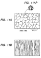
- FIG. 7 This figure illustrates a sectional view of a single-layer type flat (coin-shaped) battery.
- a secondary battery has a configuration which is basically the same as in Fig. 6, and which includes a negative electrode, a positive electrode, an ion conductive member containing an electrolyte, a battery housing and output terminals.
- numeral 701 designates a negative electrode
- numeral 703 a positive electrode
- numeral 704 a negative-electrode terminal (negative-electrode cap)
- numeral 705 a positive-electrode terminal (positive-electrode can)
- numeral 702 an ion conductive member
- numeral 706 a gasket.
- the positive electrode 703 including a positive-electrode material layer (active material layer) and the negative electrode 701 including a negative-electrode material layer (active material layer) are laminated through, at least, the ion conductive member 702.
- the resulting laminated body is received from the positive-electrode side of the battery into the positive-electrode can 705 serving as the positive-electrode terminal, and the negative-electrode side of the battery is concealed by the negative-electrode cap 704 serving as the negative-electrode terminal.
- the gasket 706 is arranged in the remaining inner part of the positive-electrode can 705.
- the preparations of the materials of the lithium battery and the assemblage of the battery as thus far explained should desirably be performed in dry air or a dry inert gas from which moisture has been satisfactorily removed.
- the material of the gasket (706) is, for example, a fluorine resin, a polyolefin resins, a polyamide resin, a polysulfone resin, or any of various sorts of rubber.
- the battery may be sealed by the "caulking" method employing an insulating packing as illustrated in Fig. 7, and may well be sealed by a method or member such as a sealed glass tube, adhesives, welding or soldering.
- any of various organic-resin materials and ceramics is used as the material of an insulating plate in Fig. 7.
- a battery housing for accommodating constituent members in a secondary battery is configured of the positive-electrode can (705) and the negative-electrode cap (704) of the battery in the example shown in Fig. 7. Since the positive-electrode can (705) and the negative-electrode cap (704) serve also as the battery housing (case) and output/input terminals in the example shown in Fig. 7, stainless steel is preferably employed therefor.
- the sheathing material of the battery is appropriately formed as a plastics member in the shape of a sheet or plate or a film, a composite member of plastics and metal such as a layer film in which a metal foil or evaporated metal film is covered with plastics films, or the like.
- the sheathing material should more preferably be a material through which water vapor and gases do not permeate, and it is essential to seal the battery proper by closing up any path of invasion of water vapor.
- the ethylenecarbonate - propylenecarbonate (1 : 1) solution of 1 mol/liter of lithium tetrafluoroborate was added by 80 parts to 20 parts of the powdery cross-linked polymer obtained, whereby a paste was prepared.
- the paste was applied onto a glass substrate coated with an indium - tin oxide (ITO), to a thickness of 50 microns.
- ITO indium - tin oxide
- the reaction vessel of a three-necked flask furnished with a circulating device, a dropping device, an agitating device and a heating device was first filled up with dried nitrogen gas. 290 parts of ion-exchanged water were put into the three-necked flask, and were agitated. Subsequently, 8.76 parts of diethyleneglycol monomethylether methacrylate and 0.24 part of ethyleneglycol dimethacrylate were agitated well and were dropped into the three-necked flask by the use of the dropping device, and the resulting system was agitated well until it became uniform.
- aqueous solution in which 0.03 part of potassium peroxosulfate was dissolved in 10 parts of ion-exchanged water was dropped as a polymerization initiator into the three-necked flask by the use of the dropping device. Polymerization was performed at 75°C for 7 hours while the interior of the three-necked flask was being agitated. A granular polymer gel thus obtained was washed with water and ethanol, and was dried. Then, a powdery cross-linked polymer was obtained.
- the ethylenecarbonate - propylenecarbonate (1 : 1) solution of 1 mol/liter of lithium tetrafluoroborate was added by 80 parts to 20 parts of the powdery cross-linked polymer obtained, whereby a paste was prepared.
- the paste was applied onto a glass substrate coated with an indium - tin oxide (ITO), to a thickness of 50 microns.
- ITO indium - tin oxide
- an ion conductive member containing a polymer gel electrolyte was manufactured.
- the ion conductive member was sandwiched between the above glass substrate and another ITO-coated glass substrate.
- the resistance of the polymer gel electrolyte between the ITO electrodes was measured by an impedance measurement which was based on a measurement signal of 1 kilohertz and which used a milliohmmeter.
- the ionic conductivity of the gel calculated from the measurement of the resistance was a value which was about 1/3 of that of Experiment 1.
- Fig. 10 is a schematic view showing an image which was observed at an acceleration voltage of 20.0 kV.
- the upper part of the figure corresponds to the surface part of the polymer gel electrolyte, and the lower part to the interior (sectional part) of the electrolyte. It is understood from the image part of the interior that the polymer gel is formed as layers or a lamination. The layered direction of the layers was perpendicular to the direction of the electric field applied during the preparation (the direction of the vector of the electric line of force).
- the resulting mixed solution was inserted into a cell which was constituted by two glass substrates with their surfaces coated with lecithin beforehand and which had a cell gap of 50 microns.
- the resulting gapped cell was sandwiched between the N-pole and S-pole of a samarium - cobalt anisotropic magnet having a residual flux density of 1 tesla, whereby a magnetic field was applied to the mixed solution.
- the cell was heated at 75°C at which the low-molecular liquid crystal exhibited a nematic state, whereby a polymerizing reaction and a cross-linking reaction were induced. Then, a filmy polymer gel was obtained.
- the resistance of the polymer gel electrolyte was measured by an impedance measurement employing a milliohmmeter, and the ionic conductivity thereof was calculated from the thickness thereof.
- the configuration of the polymer gel electrolyte obtained was observed with an electron microscope, a sectional structure having a columnar structure in which the electrolyte was regularly oriented in parallel with the applied magnetic field (with the vector of the magnetic line of force) was seen.
- the polymer gel was impregnated with an electrolyte solution of 1 mol/liter in which lithium tetrafluoroborate was dissolved in propylene carbonate, so as to carry the electrolyte solution. Then, a polymer gel electrolyte was prepared.
- a polymer gel electrolyte was prepared in the same way as in Experiment 4, except the condition that propylene carbonate was added instead of the low-molecular liquid crystal N-(4-ethoxybenzylidene-4'-butylaniline) used in Experiment 4.
- the resistance of the polymer gel electrolyte was measured by an impedance measurement employing a milliohmmeter, and the ionic conductivity thereof was calculated from the thickness thereof. Then, the ionic conductivity was about 1/6 of that exhibited in Experiment 4.
- the ion conductive member was sandwiched between the above glass substrate and another ITO-coated glass substrate, the resulting structure was connected as illustrated in Fig. 8, and the ionic conductivity of the ion conductive member was measured by a milliohmmeter in the same way as in Experiment 1. Besides, when the ion conductive member of the polymer-gel-electrolyte film obtained was observed with an electron microscope, the layered structure was seen.
- the resistance of the polymer film was measured by an impedance measurement employing a milliohmmeter, and the ionic conductivity thereof was calculated from the thickness thereof. Then, the ionic conductivity was about 1/4 of that exhibited in Experiment 5.
- the resistance of the ion conductive member was measured by an impedance measurement employing a milliohmmeter, and the ionic conductivity thereof was calculated from the thickness thereof. Besides, when the configuration of the polymer gel electrolyte obtained was observed with an electron microscope, a sectional structure in which a layered structure perpendicular to the applied electric field was oriented was seen.
- methyl methacrylate was added as a liquid-crystalline monomer instead of 4-(6-acryloyloxyhexyloxy)-4'-cyanobiphenyl, and ethyleneglycol dimethacrylate was added as a cross-linking agent instead of bisphenol-A diacrylate exhibitive of liquid-crystallinity.
- a cell was heated at 70°C to induce a polymerizing reaction and a cross-linking reaction. Thus, a filmy polymer gel was obtained.
- the resistance of the polymer gel electrolyte was measured by an impedance measurement employing a milliohmmeter, and the ionic conductivity thereof was calculated from the thickness thereof.
- the ionic conductivity was about 1/3 of that exhibited in Experiment 6.
- the cell was let stand at 75°C for 7 days. Then, a polymer gel film was obtained. Further, the obtained film was washed with 1, 4-dioxane, and it was impregnated with an electrolyte solution of 0.5 mol/liter in which lithium tetrafluoroborate was dissolved in 1, 4-dioxane, so as to carry the electrolyte solution. Then, a filmy polymer-gel electrolyte intended was obtained.
- a polymer gel film was prepared in the same way as in Experiment 7, except the condition that the polymer poly( ⁇ -benzyl-L-glutamate) exhibitive of liquid-crystallinity used in Experiment 7 was replaced with poly(methyl methacrylate). Further, a polymer gel electrolyte was prepared in the same way as in Experiment 7. Subsequently, as in Experiment 7, the resistance of the polymer gel electrolyte was measured by an impedance measurement employing a milliohmmeter, and the ionic conductivity thereof was calculated from the thickness thereof. Then, the ionic conductivity was about 1/4 of that exhibited in Experiment 7.
- the polymer film formed on the glass substrate was repeatedly immersed in fresh methanol until the surfactant was removed.
- the resulting polymer film was caused to absorb the propylene carbonate solution of 1 mol/liter of lithium tetrafluoroborate.
- an ion conductive member was manufactured.
- the ion conductive member was sandwiched between the above glass substrate and another ITO-coated glass substrate, the resulting structure was connected as illustrated in Fig. 8, and the ionic conductivity of the ion conductive member was measured by a milliohmmeter in the same way as in Experiment 1.
- Experiment 8 The processing steps of Experiment 8 were conformed to except that the surfactant in Experiment 8 was not used, and that a cross-linking reaction was induced by irradiation with light.
- a polymer gel film was prepared on an ITO-coated glass substrate.
- the polymer gel was sandwiched between the above glass substrate and another ITO-coated glass substrate.
- an impedance measurement was performed, and the ionic conductivity of the polymer gel film was calculated from the thickness thereof. Then, the ionic conductivity based on the measurement of the resistance of the film was about 1/2 of that exhibited in Experiment 8.
- the substrate was irradiated with an electron beam so as to induce a cross-linking reaction.
- a polymer gel film was prepared.
- the obtained film was washed with acetonitrile, and it was impregnated with an electrolyte solution of 1 mol/liter in which lithium tetrafluoroborate was dissolved in propylene carbonate, so as to carry the electrolyte solution.
- a polymer gel electrolyte was prepared.
- the polymer-gel-electrolyte film obtained was sandwiched between the above glass substrate and another ITO-coated glass substrate. As in Experiment 1, an impedance measurement was performed, and the ionic conductivity of the polymer-gel-electrolyte film was calculated from the thickness thereof.
- the obtained film was washed with acetonitrile, and it was impregnated with an electrolyte solution of 1 mol/liter in which lithium tetrafluoroborate was dissolved in propylene carbonate, so as to carry the electrolyte solution. Then, a polymer gel electrolyte was prepared.
- Polymer gel grains were obtained in conformity with the operations of Experiment 10 on condition that the surfactant used in Experiment 10 was not added.
- Carboxymethyl cellulose was mixed by 5 parts to 95 parts of the polymer gel powder obtained, and a solution of 50% acetone - 50% ion-exchanged water was added to the mixture, whereby a paste was prepared.
- the paste was applied onto an ITO-coated glass substrate and was dried, and it was impregnated with a potassium-hydroxide aqueous solution of 30 weight-% containing 2 weight-% of lithium hydroxide, whereby a polymer gel layer having a thickness of 50 microns was formed as in Experiment 10.
- Carboxymethyl cellulose was mixed by 5 parts to 95 parts of the polymer gel powder obtained, and a solution of 50% acetone - 50% ion-exchanged water was added to the mixture, whereby a paste was prepared.
- the paste was applied onto an ITO-coated glass substrate, and was dried.
- the resulting paste was caused to absorb a potassium-hydroxide aqueous solution of 30 weight-% containing 2 weight-% of lithium hydroxide.
- a layer of polymer gel having a thickness of 50 microns was formed.
- the polymer gel layer was sandwiched between the above glass substrate and another ITO-coated glass substrate.
- an impedance measurement was performed, and the ionic conductivity of the polymer gel layer was calculated from the thickness thereof.
- a granular polymer gel electrolyte which was prepared in such a way that the polymer gel powder obtained by the above process was caused to absorb an aqueous solution of potassium hydroxide, was observed with an electron microscope, and a regular columnar structure was seen.
- Polymer gel grains were obtained in conformity with the operations of Experiment 11 on condition that the surfactant used in Experiment 11 was not added.
- Carboxymethyl cellulose was mixed by 5 parts to 95 parts of the polymer gel powder obtained, and a solution of 50% acetone - 50% ion-exchanged water was added to the mixture, whereby a paste was prepared.
- the paste was applied onto an ITO-coated glass substrate and was dried, and it was impregnated with a potassium-hydroxide aqueous solution of 30 weight-% containing 2 weight-% of lithium hydroxide, whereby a polymer gel layer having a thickness of 50 microns was formed as in Experiment 11.
- the polymer gel layer was sandwiched between the above glass substrate and another ITO-coated glass substrate, and the ionic conductivity of the layer was measured as in Experiment 11. Then, the ionic conductivity based on the measurement of the resistance of the layer was about 1/3 of that exhibited in Experiment 11.
- Hydroxypropyl cellulose being a polymer exhibitive of liquid-crystallinity as was used in Experiment 12, was replaced with polyvinyl alcohol.
- a paste was irradiated with an electron beam so as to induce a cross-linking reaction.
- a polymer gel film was prepared on an ITO-coated glass substrate. After the polymer gel film was dried, it was impregnated with a potassium-hydroxide aqueous solution of 30 weight-% containing 2 weight-% of lithium hydroxide, whereby a polymer gel layer having a thickness of 50 microns was formed.
- the polymer gel layer was sandwiched between the above glass substrate and another ITO-coated glass substrate.
- an impedance measurement was performed, and the ionic conductivity of the layer calculated from the thickness thereof.
- the ionic conductivity based on the measurement of the resistance of the layer was about 1/2 of that exhibited in Experiment 12.
- the impedance of the polymer gel electrolyte which was prepared within the glass-made container 901 shown in Fig. 9 and which was sandwiched between the nickel plates of the opposing electrodes 902, was measured by the same operations as in Experiment 1, and the ionic conductivity of the electrolyte was calculated.
- the ionic conductivity in the direction in which the electric field was applied during the preparation of the polymer gel is about 9 times as high as the ionic conductivity in the direction in which the electric field was not applied, and it has been verified that the direction of ionic conduction is anisotropic.
- a polymer gel electrolyte for verifying the anisotropy of the ionic conductivity thereof was prepared in the same way as in Experiment 13, except that different materials to be stated below were employed for the mixed solution of the starting materials of a polymer gel and that polymerizing and cross-linking reactions were induced by the thermodecomposition of an initiator.
- the mixed solution in Experiment 13 was replaced with a mixed solution which was obtained by mixing 50 parts of methyl methacrylate as a monomer, 5 parts of ethyleneglycol dimethacrylate as a cross-linking agent, 40 parts of N-(4-ethoxybenzylidene-4'-butylaniline) being a low-molecular liquid crystal as a template, and 5 parts of 2, 2'-azobisisobutylonitrile as the initiator, and by adding 100 parts of propylene carbonate to the preceding materials.
- the resulting mixed solution was inserted into the glass container 901 so as to cover the electrodes 902 of the nickel plates, and an electric field of A. C. 100 V (at 400 Hz) was applied across the electrodes of one set of opposing nickel plates, whereby the liquid-crystal monomer was oriented. No electric field was applied across the other set of opposing nickel plates.
- the mixed solution was heated to 75°C with the electric field kept applied, whereby a polymerizing reaction and a cross-linking reaction were induced. Then, a polymer gel was obtained. After the polymer gel obtained was washed with tetrahydrofurane, the resulting polymer gel was impregnated with an electrolyte solution of 1 mol/liter in which lithium tetrafluoroborate was dissolved in propylene carbonate, so as to carry the electrolyte solution. Thus, a polymer gel electrolyte was prepared.
- the impedance between the nickel plate electrodes across which the electric field was applied during the preparation of the polymer gel, and the impedance between the nickel plate electrodes across which the electric field was not applied, were measured by the same operations as in Experiment 1, and the ionic conductivity of the electrolyte was calculated.
- the ionic conductivity in the direction in which the electric field was applied during the preparation of the polymer gel is about 12 times as high as the ionic conductivity in the direction in which the electric field was not applied, and it has been verified that the direction of ionic conduction is anisotropic.
- a sheetlike secondary battery of "name card” size (55 mm ⁇ 90 mm ⁇ 0.5 mm (thickness)) having a configuration shown in Fig. 6 was manufactured as an embodiment by the use of a polymer gel electrolyte prepared by the same process as in any of Experiments 1 to 12.
- a sheetlike secondary battery of "name card” size (55 mm ⁇ 90 mm ⁇ 0.5 mm (thickness)) having the configuration shown in Fig. 6 was manufactured as a comparative example by the use of a polymer gel electrolyte prepared by the same process as in any of Comparative Experiments 1 to 12, in order to compare the performances of the secondary battery of the present invention and that of the comparative example.
- the secondary batteries were manufactured as ones in each of which the capacity of a positive electrode is larger than that of a negative electrode, so that the capacity of the battery is determined by the negative-electrode capacity.
- a sheetlike battery was manufactured in such a way that a negative electrode and a positive electrode were fabricated and were respectively formed with polymer-gel-electrolyte layers on their surfaces to be opposed, that the negative electrode and positive electrode were laminated together with the sides of the polymer-gel-electrolyte layers opposed to each other, and that the resulting structure was sealed with moisture-proof films.
- a paste obtained at the above step 2 was applied onto a collector 609 made of an aluminum foil being 20 microns thick, and was dried. Thereafter, the thickness of the layer of the positive-electrode active material 608 (the paste) was adjusted to 90 microns by a roll press machine. Further, a lead of aluminum was connected to the aluminum foil formed with the active material layer, by an ultrasonic welder, and the resulting structure was dried at 150°C under a reduced pressure. Then, a positive electrode 607 was obtained.
- the resulting mixed solution was applied onto the active material layers of the negative electrode and positive electrode fabricated as explained in the above items (1) and (2), and a magnetic field of 2 teslas was applied in a direction perpendicular to the planes of the electrodes by an electromagnet, whereby the liquid-crystal monomer was oriented. Thereafter, the resulting structure was irradiated with ultraviolet rays to induce a polymerizing reaction and a cross-linking reaction. Then, the negative electrode and positive electrode formed with respective layers of a polymer gel electrolyte were obtained.
- the negative and positive electrodes laminated together were sandwiched between two moisture-proof films each of which was a layer film of polypropylene/aluminum foil/polyethylene terephthalate. Thereafter, the resulting structure was put into a pressure reducing apparatus to which an evacuation device including a vacuum pump was connected, and the interior thereof was brought into a reduced-pressure atmosphere so as to draw out gases. Subsequently, the resulting structure was sealed by fusion-welding the edge parts of the moisture-proof films. Then, the sheetlike battery shown in Fig. 6 was manufactured.
- a sheetlike battery was manufactured in the same way as in Embodiment 1, except the following difference from Embodiment 1:
- methyl acrylate was used instead of 4-(6-acryloyloxyhexyloxy)-4'-cyanobiphenyl being the liquid-crystalline monomer. That is, in this example, the liquid-crystal monomer serving as the template in Embodiment 1 was not used.
- a charge-and-discharge test was carried out under the conditions that one cycle consisted of charge and discharge of 0.2 C (electric current of 0.2 times a capacity/an hour) with the capacity of the manufactured secondary battery assumed to be a value calculated from the weight of the negative electrode, and a rest time period of 30 minutes, and that the cutoff voltage of the charge was set at 4.5 V, while the cutoff voltage of the discharge was set at 2.8 V.
- the charge-and-discharge test was started with the charge, and three cycles of charge-and-discharge were repeated.
- the respective values of the battery in Embodiment 1 were estimated with the normalization that the values of the battery in Comparative example 1 were set at 1.0.
- a sheetlike battery constructed as shown in Fig. 6 was manufactured in such a way that a negative electrode and a positive electrode were fabricated and were respectively formed with polymer-gel-electrolyte layers on their surfaces to be opposed, that the negative electrode and positive electrode were laminated together with the sides of the polymer gel layers opposed to each other, and that the resulting structure was sealed with moisture-proof films.
- a reaction vessel was filled with dried nitrogen gas.
- 8.76 parts of diethyleneglycol monomethylether methacrylate and 0.24 part of ethyleneglycol dimethacrylate were agitated well and were dropped into a three-necked flask by the use of a dropping device, and the resulting system was agitated well until it became uniform.
- aqueous solution in which 0.03 part of potassium peroxosulfate was dissolved in 10 parts of ion-exchanged water was dropped as a polymerization initiator into the three-necked flask by the use of the dropping device. Polymerization was performed at 75°C for 7 hours while the interior of the three-necked flask was being agitated. Thereafter, a granular polymer gel obtained was washed with water and ethanol and was dried. Then, a powdery cross-linked polymer was obtained.
- a negative electrode 604 was fabricated by the same steps as in Embodiment 1.
- a paste obtained at the above step 2 was applied onto a collector 609 made of an aluminum foil being 20 microns thick, and was dried. Thereafter, the thickness of the layer of the positive-electrode active material 608 (the paste) was adjusted to 90 microns by a roll press machine. Further, a lead of aluminum was connected to the aluminum foil formed with the active material layer, by an ultrasonic welder, and the resulting structure was dried at 150°C under a reduced pressure. Then, a positive electrode 607 was obtained.
- the negative and positive electrodes laminated together were sandwiched between two moisture-proof films each of which was a layer film of polypropylene/aluminum foil/polyethylene terephthalate. Thereafter, the resulting structure was put into a pressure reducing apparatus to which an evacuation device including a vacuum pump was connected, and the interior thereof was brought into a reduced-pressure atmosphere so as to draw out gases. Subsequently, the resulting structure was sealed by fusion-welding the edge parts of the moisture-proof films. Then, the sheetlike battery as shown in Fig. 6 was manufactured.
- a sheetlike battery was manufactured in the same way as in Embodiment 2, except the following point:
- the surfactant was not used.
- a charge-and-discharge test was carried out under the conditions that one cycle consisted of charge and discharge of 0.2 C (electric current of 0.2 times a capacity/an hour) with the capacity of the manufactured secondary battery assumed to be a value calculated from the weight of the negative electrode, and a rest time period of 30 minutes, and that the cutoff voltage of the charge was set at 4.5 V, while the cutoff voltage of the discharge was set at 2.8 V.
- the charge-and-discharge test was started with the charge, and three cycles of charge-and-discharge were repeated.
- a sheetlike battery constructed as shown in Fig. 6 was manufactured in such a way that a negative electrode and a positive electrode were fabricated and were respectively formed with polymer gel layers on their surfaces to be opposed, that the negative electrode and positive electrode were laminated together with the sides of the polymer gel layers opposed to each other, and that the resulting structure was sealed with moisture-proof films. These fabricating steps will be explained with reference to Fig. 6.
- a mixed solution was prepared in such a way that 70 parts of acrylonitrile as a monomer, 30 parts of 4-(6-acryloyloxyhexyloxy)-4'-cyanobiphenyl as a liquid-crystalline monomer, 6.5 parts of 1, 6-hexanediol diacrylate as a cross-linking agent, and 5 parts of benzoyl peroxide as an initiator were mixed into 550 parts of an electrolyte solution of 1 mol/liter in which lithium tetrafluoroborate was dissolved in a solvent consisting of propylene carbonate and ethylene carbonate at a weight ratio of 50 : 50.
- a paste was prepared by adding N-methyl-2-pyrrolidone to 95 parts of fine powder of natural graphite which were heat-treated at 2000°C in an argon gas flow and 5 parts of powder of polyvinylidene fluoride. After the prepared paste was applied onto a collector 606 of copper foil being 18 microns thick and was dried, the thickness of an active material layer (graphite layer) 605 was adjusted to 90 microns by a roll press machine. Thus, a negative electrode 604 was obtained.
- a positive electrode 607 was obtained by the same steps as in Embodiment 1.
- Colloidal silica having a grain diameter of 5 microns was dispersed as a spacer on the negative-electrode active material layer fabricated in the above item (2). Thereafter, the positive electrode fabricated in the above item (3) was laminated with the positive-electrode active material layer opposing to the negative-electrode active material layer, and the mixed monomer solution containing monomers prepared in the above item (1) was injected between the negative electrode and positive electrode defining a gap of 5 microns.
- a magnetic field of 2 teslas was applied by an electromagnet so as to act in a direction perpendicular to the planes of the negative and positive electrodes, and the initiator was decomposed at 85°C so as to induce the polymerizing and cross-linking reactions of the mixed solution.
- a polymer-gel-electrolyte layer was formed between the negative electrode and the positive electrode.
- the separator was impregnated with an electrolyte solution of 1 mol/liter in which lithium tetrafluoroborate was dissolved in a solvent consisting of propylene carbonate and ethylene carbonate at a weight ratio of 50 : 50, so as to carry the electrolyte solution.
- the resulting structure of the negative electrode/separator (electrolyte solution)/positive electrode was sandwiched between two moisture-proof films each of which was a layer film of polypropylene/aluminum foil/polyethylene terephthalate. Thereafter, the resulting structure was sealed by fusion-welding the edge parts of the moisture-proof films. Then, the sheetlike battery was manufactured.
- the constant-current charge was changed-over to the constant-voltage charge of 6 V.
- the battery was discharged with a current of 0.5 C.
- the battery was charged and discharged with the current of 0.5 C with the cutoff voltage of the charge set at 4.5 V and that of the discharge set at 2.8 V.
- a sheetlike battery constructed as shown in Fig. 6 was manufactured in such a way that a negative electrode and a positive electrode were fabricated and were respectively formed with polymer gel layers on their surfaces to be opposed, that the negative electrode and positive electrode were laminated together with the sides of the polymer gel layers opposed to each other, and that the resulting structure was sealed with moisture-proof films.
- Negative electrode 604 An expanded metal material 606 of nickel being 20 ⁇ m thick was cut into a predetermined size. Thereafter, the cut nickel piece was pressedly secured to a metal lithium foil 605 being 25 ⁇ m thick, so as to be embedded in metal lithium. The surface of the resulting metal lithium piece was etched by turning argon gas into a plasma. Thus, a negative electrode 604 was fabricated.
- the paste obtained at the above step 2 was applied onto a collector 609 made of an aluminum foil being 20 microns thick, and was dried. Thereafter, the thickness of the layer of the positive-electrode active material (the paste) 608 was adjusted to 90 microns by a roll press machine. Further, a lead of aluminum was connected to the aluminum foil formed with the active material layer, by an ultrasonic welder, and the resulting structure was dried at 150°C under a reduced pressure. Then, a positive electrode 607 was obtained.
- the negative and positive electrodes laminated together were sandwiched between two moisture-proof films each of which was a layer film of polypropylene/aluminum foil/polyethylene terephthalate. Thereafter, the resulting structure was put into a pressure reducing apparatus to which an evacuation device including a vacuum pump was connected, and the interior thereof was brought into a reduced-pressure atmosphere so as to draw out gases. Subsequently, the resulting structure was sealed by fusion-welding the edge parts of the moisture-proof films. Then, the sheetlike battery constructed as shown in Fig. 6 was manufactured.
- a sheetlike battery was manufactured in the same way as in Embodiment 4, except the following: In this comparative example, no surfactant was used at the step 1 in the preparation of the polymer gel electrolyte as explained in the item (1) of Embodiment 4.
- a sheetlike battery was manufactured in the same way as in Embodiment 4, except the following: In this comparative example, it was not performed to prepare the polymer gel electrolyte as explained in the item (1) of Embodiment 4.
- a separator which was made of a micro porous polypropylene membrane being 50 microns thick, was held between the negative and positive electrodes 604, 607 fabricated in the respective items (2) and (3) of Embodiment 4.
- the separator had been impregnated with an electrolyte solution of 1 mol/liter in which lithium tetrafluoroborate was dissolved in a solvent consisting of propylene carbonate and ethylene carbonate at a weight ratio of 50 : 50, so as to carry the electrolyte solution.
- a charge-and-discharge test was carried out under the conditions that one cycle consisted of charge and discharge of 0.2 C (electric current of 0.2 times a capacity/an hour) with the capacity of the manufactured secondary battery assumed to be a value calculated from the weight of the negative electrode, and a rest time period of 30 minutes, and that the cutoff voltage of the charge was set at 4.5 V, while the cutoff voltage of the discharge was set at 2.8 V.
- the charge-and-discharge test was started with the charge, and three cycles of charge-and-discharge were repeated. Thereafter, in the fourth cycle, the battery was charged for 3 hours by combining a constant current of 1 C and a constant voltage of 6 V. More specifically, the charge was performed with the current value of 1 C.
- the batteries of Embodiment 4 and Comparative example 4-2 were separately manufactured, and their cycle lifetimes were estimated by performing cycle lifetime tests of charge and discharge with a current of 0.5 C under the condition that the cutoff voltages of charge and discharge were respectively set at 4.5 V and 2.5 V.
- the "cycle lifetime" was defined as the number of cycles in which the capacity of the battery became below 60 % of a prescribed battery capacity.
- the normalized value of the cycle lifetime of the battery of Embodiment 4 was 97 with the cycle lifetime of the battery of Comparative example 4-2 set at 1.0.
- the dendrite of lithium was produced by the repetition of charge and discharge, and the cycle lifetime was short.
- the production of the dendrite of lithium was suppressed, and the cycle lifetime was lengthened.
- a sheetlike battery constructed as shown in Fig. 6 was manufactured in such a way that a negative electrode and a positive electrode were laminated and were respectively formed with polymer gel layers on their surfaces to-be-opposed, that the negative electrode and positive electrode were stuck together with the sides of the polymer gel layers opposed to each other, and that the resulting structure was sealed with moisture-proof films.
- the cross-linked polymer powder obtained as explained in the above item (1) was further pulverized finer. 1 part of the finer cross-linked polymer powder was added to 95 parts of fine powder of natural graphite which were heat-treated at 2000°C in an argon gas flow and 4 parts of powder of polyvinylidene fluoride. N-methyl-2-pyrrolidone was added to the resulting mixture so as to prepare a paste. After the prepared paste was applied onto a collector 606 of copper foil being 18 microns thick and was dried, the thickness of an active material layer (graphite layer) 605 was adjusted to 90 microns by a roll press machine. Thus, a negative electrode 604 was obtained.
- a positive-electrode active material layer (paste layer) 608 was adjusted to 90 microns by a roll press machine. Further, a lead of aluminum was connected to the aluminum foil formed with the active material layer, by an ultrasonic welder, and the resulting structure was dried at 150°C under a reduced pressure. Thus, a positive electrode 607 was obtained.
- An electrolyte solution of 1 mol/liter was prepared by dissolving lithium tetrafluoroborate in propylene carbonate.
- the electrolyte solution prepared in the above item (4) was dropped onto the active material layer 605 of the negative electrode 604 obtained in the above item (2), that 608 of the positive electrode 607 obtained in the above item (3) and the cross-linked polymer film 601 obtained in the above item (1), whereby both the active material layers were caused to absorb the electrolyte solution. Subsequently, the cross-linked polymer film 601 containing absorbed liquid was stacked on the active material layer 605 of the negative electrode 604, and it was overlaid with the positive electrode 607. Thus, a cell was formed.
- the cell thus formed as a stacked body was sandwiched between two moisture-proof films each of which was a layer film of polypropylene/aluminum foil/polyethylene terephthalate. Thereafter, the resulting structure was put into a pressure reducing apparatus to which an evacuation device including a vacuum pump was connected, and the interior thereof was brought into a reduced-pressure atmosphere so as to draw out gases. Subsequently, the resulting structure was sealed by fusion-welding the edge parts of the moisture-proof films. Then, the sheetlike battery constructed as shown in Fig. 6 was manufactured.
- a sheetlike battery was manufactured in the same way as in Embodiment 5, except the following: In this comparative example, no surfactant was used at the step 1 in the preparation of the polymer gel electrolyte in the item (1) of Embodiment 5. That is, in this example, the compound employed for a template in Embodiment 5 was not used.
- a charge-and-discharge test was carried out under the conditions that one cycle consisted of charge and discharge of 0.2 C (electric current of 0.2 times a capacity/an hour) with the capacity of the manufactured secondary battery assumed to be a value calculated from the weight of the negative electrode, and a rest time period of 30 minutes, and that the cutoff voltage of the charge was set at 4.5 V, while the cutoff voltage of the discharge was set at 2.8 V.
- the charge-and-discharge test was started with the charge, and three cycles of charge-and-discharge were repeated.
- the respective values of the battery in Embodiment 5 were estimated with the normalization that the values of the battery in Comparative example 5 were set at 1.0.
- the lithium secondary batteries of Embodiment 1 thru Embodiment 5 one sort of supporting electrolyte and three sorts of positive-electrode active materials were used. It is to be understood, however, that they are not restrictive, but that various sorts of supporting electrolyte and various sorts of positive-electrode active materials explained before can be used.
- the batteries manufactured in the embodiments were in the shape of sheet, batteries in various shapes such as a coin-shaped battery, a cylindrical battery or a square battery can be manufactured without being restricted to the exemplified shape.
- the ion conductive member of the present invention is especially employed, a battery in any desired shape can be manufactured.
- a sheetlike nickel-hydrogen secondary battery constructed as shown in Fig. 6 was manufactured by steps explained below.
- Mg 2 Ni alloy powder and nickel powder which had been obtained by radio-frequency melting were mixed at a mol ratio of 1 : 1. Thereafter, the mixture was kneaded by a planetary-gear ball mill. Then, amorphous magnesium - nickel alloy powder was prepared. Subsequently, copper powder as an electric-conduction assistant was mixed into the amorphous magnesium - nickel alloy powder, at a weight ratio of 3. The resulting mixed powder was secured to a punched metal piece of nickel by a roller press, and the nickel piece bearing the mixed powder was cut into a predetermined size. A lead of nickel tab was connected to the resulting nickel piece by spot welding. Then, a negative electrode was obtained.
- a foamed nickel substrate 609 having a thickness of 1.5 mm, a pore diameter of 200 microns and a porosity of 95 % was coated and packed with the paste, and it was dried at 120°C for 1 hour. The resulting substrate was pressed to adjust its thickness. Subsequently, the substrate was cut into a predetermined size, and a lead of nickel tab was connected to the substrate by spot welding. Then, a positive electrode 607 was fabricated.
- a polymer solution was prepared in such a way that 40 parts of ion-exchanged water were mixed into 60 parts of hydroxypropyl cellulose being a polymer exhibitive of liquid-crystallinity.
- the resulting fabric piece was coated with the polymer solution prepared in the above step, and it was let stand still. Thereafter, the polymer coating was irradiated with an electron beam so as to induce a cross-linking reaction. Then, a polymer gel layer supported by the nonwoven polypropylene fabric was prepared. After drying, the polymer gel layer was impregnated with an aqueous solution of 30 weight-% of potassium hydroxide containing 2 weight-% of lithium hydroxide. Thus, a polymer-gel-electrolyte layer was formed.
- the positive electrode fabricated in the above item (2) was immersed in the polymer solution prepared in the above step, and the polymer solution on the positive electrode was irradiated with an electron beam so as to induce a cross-linking reaction, whereby a polymer gel layer was formed on the positive electrode.
- the positive electrode formed with the polymer gel layer was dried, it was impregnated with the aqueous solution of 30 weight-% of potassium hydroxide containing 2 weight-% of lithium hydroxide.
- the positive electrode formed with a polymer-gel-electrolyte layer was fabricated.
- the positive electrode obtained in the above item (2) was brought into close touch with the polymer-gel-electrolyte layer supported by the nonwoven polypropylene fabric, the layer having been formed on the negative electrode as explained in the above item (3). On this occasion, the lead parts of the negative and positive electrodes were prevented from short-circuiting.
- the resulting negative and positive electrodes stuck together were sandwiched between two gas-barrier films each of which was a layer film of polypropylene/aluminum foil/polyethylene terephthalate. Thereafter, the resulting structure was put into a pressure reducing apparatus to which an evacuation device including a vacuum pump was connected, and the interior thereof was brought into a reduced-pressure atmosphere so as to draw out gases. Subsequently, the resulting structure was sealed by fusion-welding the edge parts of the gas-barrier or moisture-proof films. Then, the sheetlike battery was manufactured.
- a sheetlike battery was manufactured in the same way as in Embodiment 6, except the following:
- the polymer gel electrolyte in the item (3) of Embodiment 6 was not formed.
- a separator made of nonwoven polypropylene fabric being 200 microns thick and endowed with a hydrophilicity, which had been impregnated with an aqueous solution of 30 weight-% of potassium hydroxide containing 2 weight-% of lithium hydroxide, so as to carry the electrolyte solution, was sandwiched between the negative electrode and positive electrode which had been respectively fabricated in the items (1) and (2) of Embodiment 6.
- the laminated body of the negative electrode/separator (electrolyte solution)/positive electrode was sandwiched between two moisture-proof films each of which was a layer film of polypropylene/aluminum foil/polyethylene terephthalate. Thereafter, the resulting structure was sealed by fusion-welding the edge parts of the moisture-proof films. Then, the sheetlike battery was manufactured. In this manner, the polymer gel electrolyte in Embodiment 6 was not used in the comparative example.
- a charge-and-discharge test was carried out under the conditions that one cycle consisted of charge and discharge of 0.2 C (electric current of 0.2 times a capacity/an hour) with the capacity of the manufactured secondary battery assumed to be a value calculated from the weight of the negative electrode, and a rest time period of 30 minutes, and that the cutoff voltage of the charge was set at 1.5 V, while the cutoff voltage of the discharge was set at 0.9 V.
- the charge-and-discharge test was started with the charge, and ten cycles of charge-and-discharge were repeated.
- a coin-shaped nickel - zinc secondary battery having a sectional structure shown in Fig. 7 was manufactured by a process explained below.
- aqueous solution of dispersed tetrafluoroethylene polymer was added to a mixture consisting of 95 parts of zinc oxide powder and 5 parts of zinc powder, so that the weight ratio between the mixture and the tetrafluoroethylene polymer serving as a binder might become 95 : 5.
- the resulting mixture was kneaded into the state of a paste.
- a punched metal plate of copper was coated with the paste. After drying, the resulting copper plate was pressed by a roll press machine, whereby a zinc negative-electrode plate was obtained.
- the zinc negative-electrode plate obtained was punched into a predetermined size. Thus, a negative electrode (701) was fabricated.
- 92 % of nickel hydroxide powder and 2 % of cobalt oxide powder were mixed, and the mixture was turned into a paste by employing an aqueous solution of carboxymethyl cellulose at 2 weight-% to obtain carboxymethyl cellulose at 6 weight-% as a binder.
- a foamed nickel substrate having a thickness of 1.5 mm, a pore diameter of 200 microns and a porosity of 95 % was coated and packed with the paste, and it was dried at 120°C for 1 hour. The resulting substrate was pressed to adjust its thickness. Subsequently, an active material borne on the back surface of the substrate was exfoliated by ultrasonic waves so as to denude the nickel of a collector, and the substrate was punched into a predetermined size. Then, a positive electrode (703) was fabricated.
- the positive electrode obtained in the above item (2) was brought into close touch with the polymer-gel-electrolyte layer supported by the nonwoven polypropylene fabric, the layer having been formed on the negative electrode as explained in the above item (3).
- the laminated body of the negative electrode 701/polymer-gel-electrolyte layer 702/positive electrode 703 was inserted into a coin-shaped battery can 705 made of a titanium-clad stainless steel material, so that the denuded nickel surface of the collector of the positive electrode might come into touch with the bottom of the battery can 705.
- a gasket 706 made of polypropylene was fitted on the resulting stacked body, and a negative-electrode cap 704 was put on the resulting structure and was caulked.
- the coin-shaped battery was manufactured.
- a coin-shaped battery was manufactured in the same way as in Embodiment 7, except the following:
- the polymer gel electrolyte in the item (3) of Embodiment 7 was not formed.
- a separator made of nonwoven polypropylene fabric being 200 microns thick, which had been impregnated with an aqueous solution of 30 weight-% of potassium hydroxide containing 2 weight-% of lithium hydroxide, so as to carry the electrolyte solution, was sandwiched between the negative electrode 701 and positive electrode 703 instead of the polymer-gel-electrolyte layer.
- the laminated body of the negative electrode/separator (electrolyte solution)/positive electrode was inserted into a coin-shaped battery can 705 made of a titanium-clad stainless steel material, so that the denuded nickel surface of the collector of the positive electrode might come into touch with the bottom of the battery can 705.
- a gasket 706 made of polypropylene was fitted on the resulting laminated body, and a negative-electrode cap 704 was put on the resulting structure and was caulked. Then, the coin-shaped battery was manufactured. In this manner, the polymer gel electrolyte in Embodiment 7 was not used in the comparative example.
- the cycle lifetimes of the batteries were estimated by performing cycle lifetime tests of charge and discharge under the conditions that one cycle consisted of charge and discharge of 0.2 C (electric current of 0.2 times a capacity/an hour) with the capacity of the manufactured secondary battery assumed to be a value calculated from the weight of the negative electrode, and a rest time period of 30 minutes, and that the cutoff voltages of charge and discharge were respectively set at 2.0 V and 0.9 V.
- the "cycle lifetime" was defined as the number of cycles in which the capacity of the battery became below 60 % of a prescribed battery capacity.
- the internal resistance and the cycle lifetime of the battery of Embodiment 7 were normalized with those of the battery of Comparative example 7 set at 1.0. The results are indicated in Table 8 below.
- a tetrafluoroethylene polymer serving as a binder and the polymer gel powder obtained in the above item (1) were further mixed into a mixture consisting of 95 parts of zinc oxide powder and 5 parts of zinc powder, so that the weight ratio among the mixture, the tetrafluoroethylene polymer and the polymer gel powder might become 94 : 5 : 1.
- the resulting mixture was secured onto a punched metal plate of copper and heated by a roll press machine, whereby a zinc negative-electrode plate was obtained.
- the zinc negative-electrode plate obtained was punched into a predetermined size.
- a negative electrode (701) was fabricated.
- a tetrafluoroethylene polymer serving as a binder and the polymer gel powder obtained in the above item (1) were mixed into a mixture in which manganese dioxie, nickel oxide and cobalt oxide were mixed into acetylene black, so that the weight ratio among the mixture, the tetrafluoroethylene polymer and the polymer gel powder might become 94 : 5 : 1.
- the resulting mixture was applied onto a nickel meshwork, and it was secured and heated by a roll press machine. The resulting meshwork was punched into a predetermined size. Thus, a positive electrode (703) was fabricated.
- the polymer gel powder obtained in the above item (1) and colloidal silica having a grain diameter of 10 microns were mixed at a weight ratio of 97 : 3.
- the resulting mixture was dispersed on the surface of the negative electrode obtained in the above item (2), and an aqueous solution of 30 weight-% of potassium hydroxide containing 2 weight-% of lithium hydroxide was added to the dispersed mixture.
- a polymer-gel-electrolyte layer 702 was formed.
- the positive electrode fabricated in the above item (3) was impregnated with the aqueous solution of 30 weight-% of potassium hydroxide containing 2 weight-% of lithium hydroxide.
- a piece of air diffusing paper and a tetrafluoroethylene polymer film being a water repelling film were inserted into a battery can (positive electrode can) 705 with air intake pores, the battery can 705 being made of a titanium-clad stainless steel material.
- the positive electrode 703 obtained in the above item (3), and the negative electrode 701 covered with the polymer-gel-electrolyte layer 702 obtained in the above item (4) were brought into close touch and were inserted into the battery can 705.
- the nickel of the collector of the positive electrode was held in contact with the battery can 705 so as to be electrically conductive thereto.
- a gasket 706 made of polypropylene was fitted into the resulting can, and a negative-electrode cap 704 was put on the resulting structure and was caulked.
- the coin-shaped battery was manufactured.
- a coin-shaped battery was manufactured in the same way as in Embodiment 8, except the following:
- the polymer gel electrolyte in the item (4) of Embodiment 8 was not formed.
- a negative electrode and a positive electrode were fabricated using tetrafluoroethylene polymer powder instead of the polymer gel powder which was used for the negative and positive electrodes as explained in the respective items (2) and (3) of Embodiment 8.
- a separator made of nonwoven polypropylene fabric being 200 microns thick, which had been impregnated with an aqueous solution of 30 weight-% of potassium hydroxide containing 2 weight-% of lithium hydroxide, so as to carry the electrolyte solution, was sandwiched between the positive electrode and the negative electrode.
- the cycle lifetimes of the batteries were estimated by performing cycle lifetime tests of charge and discharge under the conditions that one cycle consisted of charge and discharge of 0.2 C (electric current of 0.2 times a capacity/an hour) with the capacity of the manufactured secondary battery assumed to be a value calculated from the weight of the negative electrode, and a rest time period of 30 minutes, and that the cutoff voltages of charge and discharge were respectively set at 2.0 V and 0.9 V.
- the "cycle lifetime" was determined as the number of cycles in which the capacity of the battery became below 60 % of a prescribed battery capacity.
- the batteries of Embodiment 8 and Comparative example 8 were separately manufactured, and they were preserved in the air for one month with the air intake pores left open.
- the present invention can provide a secondary battery of high performance employing an ion conductive member whose ionic conductivity is higher and whose discharge characteristics are superior. Further, the application of the present invention to a secondary battery employing lithium or zinc to its negative electrode makes it possible to manufacture a secondary battery in which the growth of the dendrite of lithium or zinc causing the degradation of the performance of the battery can be suppressed, and which has a longer lifetime and a higher energy density.
Landscapes
- Chemical & Material Sciences (AREA)
- Chemical Kinetics & Catalysis (AREA)
- Electrochemistry (AREA)
- General Chemical & Material Sciences (AREA)
- Engineering & Computer Science (AREA)
- Manufacturing & Machinery (AREA)
- General Physics & Mathematics (AREA)
- Condensed Matter Physics & Semiconductors (AREA)
- Physics & Mathematics (AREA)
- Inorganic Chemistry (AREA)
- Dispersion Chemistry (AREA)
- Secondary Cells (AREA)
- Battery Electrode And Active Subsutance (AREA)
- Cell Separators (AREA)
- Manufacture Of Porous Articles, And Recovery And Treatment Of Waste Products (AREA)
- Polymerisation Methods In General (AREA)
Applications Claiming Priority (4)
| Application Number | Priority Date | Filing Date | Title |
|---|---|---|---|
| JP8619798 | 1998-03-31 | ||
| JP8619798 | 1998-03-31 | ||
| JP7546699 | 1999-03-19 | ||
| JP11075466A JPH11345629A (ja) | 1998-03-31 | 1999-03-19 | 二次電池及びその製造方法 |
Publications (2)
| Publication Number | Publication Date |
|---|---|
| EP0948074A2 true EP0948074A2 (fr) | 1999-10-06 |
| EP0948074A3 EP0948074A3 (fr) | 2004-05-26 |
Family
ID=26416595
Family Applications (1)
| Application Number | Title | Priority Date | Filing Date |
|---|---|---|---|
| EP99106592A Withdrawn EP0948074A3 (fr) | 1998-03-31 | 1999-03-31 | Batterie secondaire et procédé de fabrication |
Country Status (5)
| Country | Link |
|---|---|
| US (1) | US6372387B1 (fr) |
| EP (1) | EP0948074A3 (fr) |
| JP (1) | JPH11345629A (fr) |
| KR (1) | KR100284914B1 (fr) |
| CA (1) | CA2267509C (fr) |
Cited By (13)
| Publication number | Priority date | Publication date | Assignee | Title |
|---|---|---|---|---|
| WO2001084654A1 (fr) * | 2000-04-26 | 2001-11-08 | Sanyo Electric Co., Ltd. | Electrode pour pile secondaire au lithium et pile secondaire au lithium |
| WO2003032427A1 (fr) * | 2001-10-01 | 2003-04-17 | Matsushita Electric Industrial Co., Ltd. | Accumulateur alcalin ferme |
| EP1037294A3 (fr) * | 1999-03-17 | 2003-07-30 | Noboru Oyama | Electrolyte polymère |
| WO2002033765A3 (fr) * | 2000-10-18 | 2003-10-02 | Mitsui Du Pont Polychemical | Electrolyte polymere geliforme et son utilisation |
| US6953642B2 (en) | 2000-12-21 | 2005-10-11 | Canon Kabushiki Kaisha | Ion conductor structural body, process for producing said ion conductor structural body, rechargeable battery provided with said ion conductor structural body and process for producing said rechargeable battery |
| EP1615286A1 (fr) * | 2004-07-05 | 2006-01-11 | Polymatech Co., Ltd. | Membrane à électrolyte polymère conductrice d'ions et sa méthode de fabrication |
| US7153607B2 (en) | 2000-09-11 | 2006-12-26 | Matsushita Electric Industrial Co., Ltd. | Alkaline zinc secondary cell and method for preparation thereof |
| EP1892260A4 (fr) * | 2005-06-16 | 2011-05-04 | Nissan Motor | Article subissant une deformation en reaction a un stimulus, et partie de vehicule utilisant cet article |
| WO2014035753A1 (fr) * | 2012-08-29 | 2014-03-06 | Corning Incorporated | Électrolyte composite conducteur ionique |
| CN108010736A (zh) * | 2018-01-12 | 2018-05-08 | 西安交通大学 | 基于泡沫镍模板构筑NiCo2S4@Ni(OH)2@PPy材料用于超级电容器的方法 |
| CN111696792A (zh) * | 2020-06-30 | 2020-09-22 | 苏州大学 | 一种基于插层式赝电容的有机纳米负极及其制备方法和应用 |
| WO2024084309A1 (fr) * | 2022-10-20 | 2024-04-25 | Medtronic, Inc. | Cathode et son procédé de formation |
| DE102022130156A1 (de) * | 2022-11-15 | 2024-05-16 | Schaeffler Technologies AG & Co. KG | Schichtaufbau für eine elektrochemische Zelle und Verfahren zur Herstellung eines Layers einer elektrochemischen Zelle |
Families Citing this family (65)
| Publication number | Priority date | Publication date | Assignee | Title |
|---|---|---|---|---|
| JP3620703B2 (ja) * | 1998-09-18 | 2005-02-16 | キヤノン株式会社 | 二次電池用負極電極材、電極構造体、二次電池、及びこれらの製造方法 |
| JP4636644B2 (ja) * | 2000-01-17 | 2011-02-23 | 富士フイルム株式会社 | 電解質組成物、電気化学電池およびイオン性液晶モノマー |
| GB0016057D0 (en) * | 2000-06-30 | 2000-08-23 | Aea Technology Plc | A method of assembling a cell |
| JP3654180B2 (ja) * | 2000-12-19 | 2005-06-02 | 古河電池株式会社 | 固体状電解質およびそれを用いた電池 |
| US7759002B2 (en) * | 2001-02-15 | 2010-07-20 | Integral Technologies, Inc. | Low cost electrical terminals manufactured from conductive loaded resin-based materials |
| EP1313158A3 (fr) * | 2001-11-20 | 2004-09-08 | Canon Kabushiki Kaisha | Materiau d'électrode pour pile rechargeable au lithium, électrode comprenant ce matériau, pile rechargeable au lithium comprenant une telle électrode et procédé de fabrication |
| JP4135469B2 (ja) | 2002-10-30 | 2008-08-20 | 日産自動車株式会社 | ポリマー電池、組電池および車両 |
| US20040129578A1 (en) * | 2003-01-07 | 2004-07-08 | Mclachlan David | Electrostatic fluid treatment apparatus and method |
| DE10304824A1 (de) * | 2003-01-31 | 2004-08-12 | Varta Microbattery Gmbh | Dünne elektronische Chipkarte |
| JP2004265806A (ja) * | 2003-03-04 | 2004-09-24 | Canon Inc | リチウム金属複合酸化物粒子、前記リチウム金属複合酸化物粒子の製造方法、前記リチウム金属複合酸化物粒子を含有す電極構造体、前記電極構造体の製造方法、及び前記電極構造体を有するリチウム二次電池 |
| JP4366101B2 (ja) * | 2003-03-31 | 2009-11-18 | キヤノン株式会社 | リチウム二次電池 |
| JP2004356048A (ja) * | 2003-05-30 | 2004-12-16 | Canon Inc | リチウム二次電池用電極材料、前記電極材料を有する電極構造体及び前記電極構造体を有するリチウム二次電池 |
| DE10328316A1 (de) | 2003-06-23 | 2005-01-20 | Grünenthal GmbH | Verfahren zur Herstellung von Dimethyl-(3-aryl-buthyl)-aminverbindungen als pharmazeutische Wirkstoffe |
| JP2005019064A (ja) * | 2003-06-24 | 2005-01-20 | Canon Inc | イオン伝導構造体、二次電池及びそれらの製造方法 |
| JP4095499B2 (ja) * | 2003-06-24 | 2008-06-04 | キヤノン株式会社 | リチウム二次電池用の電極材料、電極構造体及びリチウム二次電池 |
| KR100508925B1 (ko) * | 2003-07-01 | 2005-08-17 | 삼성에스디아이 주식회사 | 리튬 이차 전지용 고분자 전해질 및 이를 포함하는 리튬이차 전지 |
| JP4449447B2 (ja) * | 2003-12-22 | 2010-04-14 | 日産自動車株式会社 | 固体電解質電池の製造方法 |
| US7691536B2 (en) * | 2004-02-20 | 2010-04-06 | Excellatron Solid State, Llc | Lithium oxygen batteries and method of producing same |
| US8383226B2 (en) * | 2004-03-12 | 2013-02-26 | University Of Maryland | Structures and methods for increasing the speed of electroactive polymers |
| JP2005317902A (ja) * | 2004-03-29 | 2005-11-10 | Kuraray Co Ltd | 電気二重層キャパシタ用電解質組成物及びそれを用いた電気二重層キャパシタ |
| JP2006147210A (ja) * | 2004-11-17 | 2006-06-08 | Hitachi Ltd | 二次電池及びその製造方法 |
| US7615314B2 (en) * | 2004-12-10 | 2009-11-10 | Canon Kabushiki Kaisha | Electrode structure for lithium secondary battery and secondary battery having such electrode structure |
| US20060134410A1 (en) * | 2004-12-20 | 2006-06-22 | Mackey Larry N | Polymeric structures comprising an unsubstituted hydroxyl polymer and processes for making same |
| JP2006179424A (ja) * | 2004-12-24 | 2006-07-06 | Toyota Motor Corp | 電池の製造方法 |
| KR100751331B1 (ko) * | 2005-05-16 | 2007-08-22 | 삼성에스디아이 주식회사 | 고분자 전해액 및 이를 포함하는 염료감응 태양전지 |
| KR100702859B1 (ko) * | 2005-05-27 | 2007-04-03 | 부산대학교 산학협력단 | 액정 물질을 포함하는 고체 전해질 및 이를 이용한염료감응형 태양전지 소자 |
| JP4753655B2 (ja) * | 2005-08-03 | 2011-08-24 | 三洋電機株式会社 | リチウム二次電池 |
| KR100705738B1 (ko) * | 2005-09-16 | 2007-04-09 | 강봉섭 | 전해질이 분할된 리튬 전지 |
| DE102005052588A1 (de) | 2005-11-02 | 2007-05-10 | Grünenthal GmbH | Verfahren zur Herstellung substituierter Dimethyl-(3-aryl-butyl)-amin-Verbindungen mittels homogener Katalyse |
| JP5361116B2 (ja) * | 2006-03-31 | 2013-12-04 | 小林製薬株式会社 | 含水ゲル |
| US8080335B2 (en) * | 2006-06-09 | 2011-12-20 | Canon Kabushiki Kaisha | Powder material, electrode structure using the powder material, and energy storage device having the electrode structure |
| KR100758383B1 (ko) * | 2006-07-20 | 2007-09-14 | 경상대학교산학협력단 | 리튬/유황이차전지용 탄소 코팅 유황전극 |
| TWI496762B (zh) | 2006-07-24 | 2015-08-21 | 製備(1r,2r)-3-(3-二甲胺基-1-乙基-2-甲基-丙基)-酚之方法 | |
| US20080070103A1 (en) * | 2006-09-19 | 2008-03-20 | Caleb Technology Corporation | Activation of Anode and Cathode in Lithium-Ion Polymer Battery |
| US20080070104A1 (en) * | 2006-09-19 | 2008-03-20 | Caleb Technology Corporation | Forming Polymer Electrolyte Coating on Lithium-Ion Polymer Battery Electrode |
| US20080070108A1 (en) * | 2006-09-19 | 2008-03-20 | Caleb Technology Corporation | Directly Coating Solid Polymer Composite Having Edge Extensions on Lithium-Ion Polymer Battery Electrode Surface |
| US7527894B2 (en) | 2006-09-19 | 2009-05-05 | Caleb Technology Corporation | Identifying defective electrodes in lithium-ion polymer batteries |
| JP2009164104A (ja) | 2007-09-06 | 2009-07-23 | Canon Inc | 負極用電極材料、その製造方法ならびに該材料を用いた電極構造体及び蓄電デバイス |
| WO2010111308A1 (fr) * | 2009-03-23 | 2010-09-30 | Tda Research, Inc. | Polyélectrolyte remplie d'électrolyte liquide |
| US8573018B2 (en) * | 2010-01-15 | 2013-11-05 | Essex Group, Inc. | System for manufacturing wire |
| US7931985B1 (en) * | 2010-11-08 | 2011-04-26 | International Battery, Inc. | Water soluble polymer binder for lithium ion battery |
| US8076026B2 (en) | 2010-02-05 | 2011-12-13 | International Battery, Inc. | Rechargeable battery using an aqueous binder |
| CN101807717A (zh) * | 2010-04-20 | 2010-08-18 | 诺莱特科技(苏州)有限公司 | 一种凝胶电解液及其制备方法以及使用该凝胶电解液的电池及其制备方法 |
| US20110143206A1 (en) * | 2010-07-14 | 2011-06-16 | International Battery, Inc. | Electrode for rechargeable batteries using aqueous binder solution for li-ion batteries |
| US8102642B2 (en) * | 2010-08-06 | 2012-01-24 | International Battery, Inc. | Large format ultracapacitors and method of assembly |
| CN103109397B (zh) * | 2010-09-29 | 2016-02-24 | 爱斯佩克株式会社 | 电极对干燥法、锂离子二次电池制造法、双电层电容器制造法、锂离子电容器制造法 |
| EP2736096B1 (fr) | 2011-07-20 | 2017-11-08 | GS Yuasa International Ltd. | Batterie de forme cylindrique |
| JP5979147B2 (ja) | 2011-07-20 | 2016-08-24 | 株式会社Gsユアサ | 円筒形電池 |
| CN103427125B (zh) * | 2012-05-15 | 2016-04-13 | 清华大学 | 硫基聚合物锂离子电池的循环方法 |
| US9819055B2 (en) * | 2013-03-14 | 2017-11-14 | Bigzet Incorporated | Electrolyte and sulfuric acid battery containing same |
| JP6081392B2 (ja) * | 2013-04-04 | 2017-02-15 | 本田技研工業株式会社 | 電解質−正極構造体及びそれを備えるリチウムイオン二次電池 |
| EP3130025B1 (fr) * | 2014-05-15 | 2021-07-07 | Amtek Research International, LLC. | Électrolytes de gel réticulés de façon covalente |
| JP2016046096A (ja) * | 2014-08-22 | 2016-04-04 | トヨタ紡織株式会社 | 不織布セパレータ、不織布セパレータの製造方法、及び不織布セパレータを用いた二次電池 |
| US9666852B2 (en) * | 2014-10-02 | 2017-05-30 | Ford Global Technologies, Llc | Composite separator with aligned particles |
| US10522874B2 (en) * | 2016-11-01 | 2019-12-31 | The Boeing Company | Solid state fiber-based battery system and method of forming same |
| DE102017118310B4 (de) * | 2017-08-11 | 2023-07-27 | Deutsches Zentrum für Luft- und Raumfahrt e.V. | Als elektrochemische Speichervorrichtung ausgebildetes Faserverbundbauteil sowie Verfahren zu dessen Herstellung |
| CN107331818B (zh) * | 2017-08-11 | 2023-06-02 | 烟台创为新能源科技股份有限公司 | 一种设有置换装置的三元电池组安全结构 |
| JP7184509B2 (ja) * | 2017-10-25 | 2022-12-06 | トヨタ自動車株式会社 | セパレータおよび非水電解質二次電池 |
| WO2019131779A1 (fr) * | 2017-12-27 | 2019-07-04 | 日立金属株式会社 | Matériau actif d'électrode positive pour accumulateurs au lithium-ion, procédé de production de matériau actif d'électrode positive pour accumulateurs au lithium-ion, et accumulateur au lithium-ion |
| KR102608245B1 (ko) | 2019-01-21 | 2023-11-29 | 삼성전자주식회사 | 전기 전도성 복합막, 그 제조 방법, 이를 포함하는 이차전지와 전자기기 |
| WO2021253128A1 (fr) * | 2020-06-17 | 2021-12-23 | Salient Energy Inc. | Séparateurs pour cellules et batteries au zinc-ion aqueux, batteries au zinc-métal, et procédés de fabrication d'un séparateur destiné à être utilisé dans une batterie au zinc-métal |
| CN112331902B (zh) * | 2020-11-26 | 2025-08-12 | 武汉逸飞激光智能装备有限公司 | 一种电芯包胶系统 |
| CN114497762B (zh) * | 2022-02-28 | 2023-09-08 | 贺州学院 | 一种“三明治”结构凝胶电解质膜及其电池的制备方法 |
| CN116080406B (zh) * | 2023-04-10 | 2023-06-09 | 深圳市锐深科技有限公司 | 电动轮船动力电池组监测方法,装置,介质及电子设备 |
| CN120203539B (zh) * | 2025-03-27 | 2026-03-17 | 厦门大学 | 一种全集成自供电电致变色凝胶应变传感器及其应用 |
Family Cites Families (7)
| Publication number | Priority date | Publication date | Assignee | Title |
|---|---|---|---|---|
| US5280078A (en) * | 1981-11-27 | 1994-01-18 | Gregor Harry P | Homopolymers and copolymers of acrylamide N-substituted acrylamide or N-substituted methacrylamide solid state cross-linked with polyamines or polyols |
| US4786277A (en) * | 1986-11-21 | 1988-11-22 | Trustees Of Boston University | Electrodes, electrode assemblies, methods, and systems for tissue stimulation |
| JPH02181367A (ja) * | 1989-01-06 | 1990-07-16 | Yamaha Motor Co Ltd | 燃料電池用セパレータとその製造方法 |
| US5296318A (en) * | 1993-03-05 | 1994-03-22 | Bell Communications Research, Inc. | Rechargeable lithium intercalation battery with hybrid polymeric electrolyte |
| US5609974A (en) | 1995-08-04 | 1997-03-11 | Battery Engineering, Inc. | Rechargeable battery polymeric electrolyte |
| JPH10204244A (ja) * | 1997-01-21 | 1998-08-04 | Nitto Denko Corp | リチウムイオン伝導性ポリマ―電解質とリチウムイオン電池 |
| US6432585B1 (en) * | 1997-01-28 | 2002-08-13 | Canon Kabushiki Kaisha | Electrode structural body, rechargeable battery provided with said electrode structural body, and rechargeable battery |
-
1999
- 1999-03-19 JP JP11075466A patent/JPH11345629A/ja active Pending
- 1999-03-30 CA CA002267509A patent/CA2267509C/fr not_active Expired - Fee Related
- 1999-03-31 US US09/282,417 patent/US6372387B1/en not_active Expired - Lifetime
- 1999-03-31 EP EP99106592A patent/EP0948074A3/fr not_active Withdrawn
- 1999-03-31 KR KR1019990011105A patent/KR100284914B1/ko not_active Expired - Fee Related
Non-Patent Citations (1)
| Title |
|---|
| None |
Cited By (35)
| Publication number | Priority date | Publication date | Assignee | Title |
|---|---|---|---|---|
| EP1037294A3 (fr) * | 1999-03-17 | 2003-07-30 | Noboru Oyama | Electrolyte polymère |
| US7105254B2 (en) | 1999-03-17 | 2006-09-12 | Noboru Oyama | Polymer electrolyte |
| US7122279B2 (en) | 2000-04-26 | 2006-10-17 | Sanyo Electric Co., Ltd. | Electrode for rechargeable lithium battery and rechargeable lithium battery |
| CN100421284C (zh) * | 2000-04-26 | 2008-09-24 | 三洋电机株式会社 | 可再充电锂电池的电极和可再充电锂电池 |
| CN1306634C (zh) * | 2000-04-26 | 2007-03-21 | 三洋电机株式会社 | 可再充电锂电池的电极和可再充电锂电池 |
| CN1306633C (zh) * | 2000-04-26 | 2007-03-21 | 三洋电机株式会社 | 可再充电锂电池的电极和可再充电锂电池 |
| WO2001084654A1 (fr) * | 2000-04-26 | 2001-11-08 | Sanyo Electric Co., Ltd. | Electrode pour pile secondaire au lithium et pile secondaire au lithium |
| US7153607B2 (en) | 2000-09-11 | 2006-12-26 | Matsushita Electric Industrial Co., Ltd. | Alkaline zinc secondary cell and method for preparation thereof |
| WO2002033765A3 (fr) * | 2000-10-18 | 2003-10-02 | Mitsui Du Pont Polychemical | Electrolyte polymere geliforme et son utilisation |
| AU2001295953B2 (en) * | 2000-10-18 | 2007-03-22 | E.I. Du Pont De Nemours And Company | Gel-type polymer electrolyte and use thereof |
| CN1307740C (zh) * | 2000-10-18 | 2007-03-28 | 杜邦-三井聚合化学品株式会社 | 凝胶型聚合物电解质及其应用 |
| KR100866242B1 (ko) * | 2000-10-18 | 2008-10-30 | 듀폰-미츠이 폴리케미칼 가부시키가이샤 | 겔형 중합체 전해질 및 그의 용도 |
| US7557166B2 (en) | 2000-10-18 | 2009-07-07 | Du Pont-Mitsui Polychemicals Co. Ltd | Gel-type polymer electrolyte and use thereof |
| US6953642B2 (en) | 2000-12-21 | 2005-10-11 | Canon Kabushiki Kaisha | Ion conductor structural body, process for producing said ion conductor structural body, rechargeable battery provided with said ion conductor structural body and process for producing said rechargeable battery |
| US7235333B2 (en) | 2000-12-21 | 2007-06-26 | Canon Kabushiki Kaisha | Ion conductor structural body, process for producing said ion conductor structural body, rechargeable battery provided with said ion conductor structural body and process for producing said rechargeable battery |
| US7402361B2 (en) | 2000-12-21 | 2008-07-22 | Canon Kabushiki Kaisha | Ion conductor structural body and process for producing ion conductor structural body |
| US7294433B2 (en) | 2001-10-01 | 2007-11-13 | Matsushita Electric Industrial Co., Ltd. | Closed alkaline storage battery |
| WO2003032427A1 (fr) * | 2001-10-01 | 2003-04-17 | Matsushita Electric Industrial Co., Ltd. | Accumulateur alcalin ferme |
| EP1615286A1 (fr) * | 2004-07-05 | 2006-01-11 | Polymatech Co., Ltd. | Membrane à électrolyte polymère conductrice d'ions et sa méthode de fabrication |
| US7540991B2 (en) | 2004-07-05 | 2009-06-02 | Polymatech Co., Ltd. | Ion conductive polymer electrolyte membrane and production method for the same |
| EP1892260A4 (fr) * | 2005-06-16 | 2011-05-04 | Nissan Motor | Article subissant une deformation en reaction a un stimulus, et partie de vehicule utilisant cet article |
| US8673439B2 (en) | 2005-06-16 | 2014-03-18 | Nissan Motor Co., Ltd. | Article undergoing stimulus-responsive deformation and vehicle part using the same |
| US8137799B2 (en) | 2005-06-16 | 2012-03-20 | Nissan Motor Co., Ltd. | Article undergoing stimulus-responsive deformation and vehicle part using the same |
| EP2394845A1 (fr) * | 2005-06-16 | 2011-12-14 | Nissan Motor Co., Ltd. | Article subissant une déformation en réaction à un stimulus, et partie de véhicule utilisant cet article |
| CN104995764B (zh) * | 2012-08-29 | 2017-03-01 | 康宁股份有限公司 | 离子导电复合电解质 |
| CN104995764A (zh) * | 2012-08-29 | 2015-10-21 | 康宁股份有限公司 | 离子导电复合电解质 |
| US9502729B2 (en) | 2012-08-29 | 2016-11-22 | Corning Incorporated | Ion-conducting composite electrolyte comprising path-engineered particles |
| WO2014035753A1 (fr) * | 2012-08-29 | 2014-03-06 | Corning Incorporated | Électrolyte composite conducteur ionique |
| EP3496183A1 (fr) * | 2012-08-29 | 2019-06-12 | Corning Incorporated | Électrolyte composite conducteur d'ions comprenant des particules à ingénierie de voie |
| CN108010736A (zh) * | 2018-01-12 | 2018-05-08 | 西安交通大学 | 基于泡沫镍模板构筑NiCo2S4@Ni(OH)2@PPy材料用于超级电容器的方法 |
| CN108010736B (zh) * | 2018-01-12 | 2020-03-31 | 西安交通大学 | 基于泡沫镍模板构筑NiCo2S4@Ni(OH)2@PPy材料用于超级电容器的方法 |
| CN111696792A (zh) * | 2020-06-30 | 2020-09-22 | 苏州大学 | 一种基于插层式赝电容的有机纳米负极及其制备方法和应用 |
| WO2024084309A1 (fr) * | 2022-10-20 | 2024-04-25 | Medtronic, Inc. | Cathode et son procédé de formation |
| US20240234810A9 (en) * | 2022-10-20 | 2024-07-11 | Medtronic, Inc. | Cathode and method of forming the same |
| DE102022130156A1 (de) * | 2022-11-15 | 2024-05-16 | Schaeffler Technologies AG & Co. KG | Schichtaufbau für eine elektrochemische Zelle und Verfahren zur Herstellung eines Layers einer elektrochemischen Zelle |
Also Published As
| Publication number | Publication date |
|---|---|
| JPH11345629A (ja) | 1999-12-14 |
| CA2267509A1 (fr) | 1999-09-30 |
| EP0948074A3 (fr) | 2004-05-26 |
| CA2267509C (fr) | 2004-01-13 |
| KR100284914B1 (ko) | 2001-03-15 |
| US6372387B1 (en) | 2002-04-16 |
| KR19990078427A (ko) | 1999-10-25 |
Similar Documents
| Publication | Publication Date | Title |
|---|---|---|
| CA2267509C (fr) | Batterie d'accumulateurs et son procede de fabrication | |
| US6558847B1 (en) | Metal oxide of porous structure, electrode structure, secondary battery, and methods for producing them | |
| US5888666A (en) | Secondary battery | |
| CN113437275B (zh) | 正极活性材料、电化学装置与电子设备 | |
| US7235333B2 (en) | Ion conductor structural body, process for producing said ion conductor structural body, rechargeable battery provided with said ion conductor structural body and process for producing said rechargeable battery | |
| US5853914A (en) | Rechargeable lithium battery having a specific pressure means comprising a polymer gel material | |
| JP4630857B2 (ja) | 二次電池の製造方法 | |
| KR101498330B1 (ko) | 전지용 세퍼레이터와 그 제조 방법 및 리튬 이온 이차 전지와 그 제조 방법 | |
| JPH08171901A (ja) | 二次電池用負極、該負極を有する二次電池及び電極の作製方法 | |
| JP3246596B2 (ja) | 二次電池 | |
| US8852804B2 (en) | Negative electrode for lithium ion secondary battery and lithium ion secondary battery including the same | |
| KR100462668B1 (ko) | 폴리머 전지 | |
| CA2640438A1 (fr) | Electrode pour une pile electrochimique comprenant de l'hydroxyde de nickel mesoporeux | |
| CN113410523B (zh) | 一种柔性金属有机框架基塑晶电解质及其制备方法和应用 | |
| US20050019668A1 (en) | Ionic conduction structural member, secondary battery and method of producing same | |
| KR20030097699A (ko) | 음극 재료 및 그것을 사용한 전지 | |
| JP4161437B2 (ja) | リチウム電池 | |
| JP4132945B2 (ja) | 非水電解質リチウムイオン電池とそのためのセパレータ | |
| JP2004356044A (ja) | イオン伝導体の製造方法および二次電池の製造方法 | |
| JPH0850893A (ja) | 二次電池用電極 | |
| Kuwahara et al. | Development of anion conductive gel polymer electrolytes with high ion conductivity and long-term stability for rechargeable zinc air battery | |
| JP2000106212A (ja) | リチウム電池 | |
| JPS62168348A (ja) | 二次電池 | |
| CN118899439A (zh) | 负极浆料及其制备方法、锂离子电池负极和锂离子电池 | |
| JP2001068158A (ja) | リチウム電池 |
Legal Events
| Date | Code | Title | Description |
|---|---|---|---|
| PUAI | Public reference made under article 153(3) epc to a published international application that has entered the european phase |
Free format text: ORIGINAL CODE: 0009012 |
|
| AK | Designated contracting states |
Kind code of ref document: A2 Designated state(s): AT BE CH CY DE DK ES FI FR GB GR IE IT LI LU MC NL PT SE |
|
| AX | Request for extension of the european patent |
Free format text: AL;LT;LV;MK;RO;SI |
|
| PUAL | Search report despatched |
Free format text: ORIGINAL CODE: 0009013 |
|
| AK | Designated contracting states |
Kind code of ref document: A3 Designated state(s): AT BE CH CY DE DK ES FI FR GB GR IE IT LI LU MC NL PT SE |
|
| AX | Request for extension of the european patent |
Extension state: AL LT LV MK RO SI |
|
| RIC1 | Information provided on ipc code assigned before grant |
Ipc: 7H 01M 6/16 B Ipc: 7H 01M 10/38 B Ipc: 7C 08J 9/00 B Ipc: 7C 08F 2/48 B Ipc: 7H 01M 6/18 B Ipc: 7H 01M 10/40 B Ipc: 7H 01M 10/04 A |
|
| 17P | Request for examination filed |
Effective date: 20041126 |
|
| AKX | Designation fees paid |
Designated state(s): DE FR GB IT NL |
|
| 17Q | First examination report despatched |
Effective date: 20050124 |
|
| RIC1 | Information provided on ipc code assigned before grant |
Ipc: H01M 10/052 20100101AFI20130528BHEP Ipc: H01M 10/0569 20100101ALI20130528BHEP Ipc: H01M 2/16 20060101ALI20130528BHEP Ipc: H01M 10/26 20060101ALI20130528BHEP Ipc: H01M 2/18 20060101ALI20130528BHEP Ipc: H01M 10/24 20060101ALI20130528BHEP Ipc: H01M 10/0565 20100101ALI20130528BHEP |
|
| GRAP | Despatch of communication of intention to grant a patent |
Free format text: ORIGINAL CODE: EPIDOSNIGR1 |
|
| INTG | Intention to grant announced |
Effective date: 20130705 |
|
| STAA | Information on the status of an ep patent application or granted ep patent |
Free format text: STATUS: THE APPLICATION HAS BEEN WITHDRAWN |
|
| 18W | Application withdrawn |
Effective date: 20131029 |