EP0949082A1 - Blattandrückelement für Blattzufuhr - Google Patents
Blattandrückelement für Blattzufuhr Download PDFInfo
- Publication number
- EP0949082A1 EP0949082A1 EP99106928A EP99106928A EP0949082A1 EP 0949082 A1 EP0949082 A1 EP 0949082A1 EP 99106928 A EP99106928 A EP 99106928A EP 99106928 A EP99106928 A EP 99106928A EP 0949082 A1 EP0949082 A1 EP 0949082A1
- Authority
- EP
- European Patent Office
- Prior art keywords
- sheet
- pressing
- coil spring
- pressing member
- printhead
- Prior art date
- Legal status (The legal status is an assumption and is not a legal conclusion. Google has not performed a legal analysis and makes no representation as to the accuracy of the status listed.)
- Granted
Links
Images


Classifications
-
- B—PERFORMING OPERATIONS; TRANSPORTING
- B41—PRINTING; LINING MACHINES; TYPEWRITERS; STAMPS
- B41J—TYPEWRITERS; SELECTIVE PRINTING MECHANISMS, i.e. MECHANISMS PRINTING OTHERWISE THAN FROM A FORME; CORRECTION OF TYPOGRAPHICAL ERRORS
- B41J13/00—Devices or arrangements of selective printing mechanisms, e.g. ink-jet printers or thermal printers, specially adapted for supporting or handling copy material in short lengths, e.g. sheets
- B41J13/02—Rollers
- B41J13/076—Construction of rollers; Bearings therefor
-
- B—PERFORMING OPERATIONS; TRANSPORTING
- B65—CONVEYING; PACKING; STORING; HANDLING THIN OR FILAMENTARY MATERIAL
- B65H—HANDLING THIN OR FILAMENTARY MATERIAL, e.g. SHEETS, WEBS, CABLES
- B65H5/00—Feeding articles separated from piles; Feeding articles to machines
- B65H5/06—Feeding articles separated from piles; Feeding articles to machines by rollers or balls, e.g. between rollers
- B65H5/062—Feeding articles separated from piles; Feeding articles to machines by rollers or balls, e.g. between rollers between rollers or balls
-
- B—PERFORMING OPERATIONS; TRANSPORTING
- B41—PRINTING; LINING MACHINES; TYPEWRITERS; STAMPS
- B41J—TYPEWRITERS; SELECTIVE PRINTING MECHANISMS, i.e. MECHANISMS PRINTING OTHERWISE THAN FROM A FORME; CORRECTION OF TYPOGRAPHICAL ERRORS
- B41J13/00—Devices or arrangements of selective printing mechanisms, e.g. ink-jet printers or thermal printers, specially adapted for supporting or handling copy material in short lengths, e.g. sheets
- B41J13/02—Rollers
-
- B—PERFORMING OPERATIONS; TRANSPORTING
- B65—CONVEYING; PACKING; STORING; HANDLING THIN OR FILAMENTARY MATERIAL
- B65H—HANDLING THIN OR FILAMENTARY MATERIAL, e.g. SHEETS, WEBS, CABLES
- B65H2402/00—Constructional details of the handling apparatus
- B65H2402/50—Machine elements
- B65H2402/54—Springs, e.g. helical or leaf springs
-
- B—PERFORMING OPERATIONS; TRANSPORTING
- B65—CONVEYING; PACKING; STORING; HANDLING THIN OR FILAMENTARY MATERIAL
- B65H—HANDLING THIN OR FILAMENTARY MATERIAL, e.g. SHEETS, WEBS, CABLES
- B65H2404/00—Parts for transporting or guiding the handled material
- B65H2404/10—Rollers
- B65H2404/11—Details of cross-section or profile
- B65H2404/112—Means for varying cross-section
- B65H2404/1122—Means for varying cross-section for rendering elastically deformable
- B65H2404/11221—Means for varying cross-section for rendering elastically deformable involving spring
Definitions
- the nozzle orifices of a printhead selectively eject ink drops onto a printing paper in accordance with print information while synchronizing with a relative movement of a printhead relative to a printing paper.
- the sheet-pressing member has a large spring constant, and inevitably suffers from dimensional variations. For this reason, work to properly set a pressing force is very difficult.
- the sheet-pressing member 23 is constructed such that the eddy-current shaped pressing portion (e.g., a flat spiral spring) 23a of large diameter flexibly presses the slip sheet S against the sheet feed roller.
- a spring constant of it measured in the pressing direction may be set to be small when comparing with the conventional one.
- the sheet-pressing member takes an integral form.
- the feature of the integral form contributes to reduction of the number of required component parts and size reduction, and further easy assembling.
- the ink jet printer equipped with the thus constructed sheet feeding mechanism succeeds in solving the wet-ink transfer problem in which ink is transferred from the sheet feeding mechanism to a printing paper immediately after it is printed, viz., the paper bearing printed characters, for example, which are still wet since it is not fixed. Further, the printer is capable of stably feeding the printing paper and hence printing at high print quality.
- the sheet-pressing members may include pressing portions for pressing down both sides of a region on the sheet immediately after characters, for example, are printed on the sheet.
- the thus constructed printer may include a wiper means for wiping ink stuck onto the ink discharging orifices while moving relatively to the ink discharging orifices, wherein the sheet-pressing members include pressing portions for pressing down the sheet while being located at positions out of a region including the ink discharging orifices when viewed in the wiping direction of the wiper means.
- a plurality of sheet feeding mechanisms 20, which will be described in detail later, are disposed in the upper portion of the printer main body, specifically at positions adjacent to the platen 10 and located downstream when viewed in the sheet feeding direction A.
- a discharge outlet 13 is formed located downstream of the sheet feeding mechanism 20 when viewed in the sheet feeding direction A.
- a printed slip sheet S is discharged through the discharge outlet 13.
- a roll paper R is located in the rear portion within the main body case 2 of the printer 1.
- a paper exit port 12 is provided in the upper portion within the case 2. The leading end of the roll paper R is led out of the paper exit port 12.
- the roll paper R passes through a paper transporting path, which is different from a transporting path of the slip sheet S, although when the printer prints on the roll paper R, the roll paper R passes through the gap between the printhead 4a of the printing unit 4 and the platen 10.
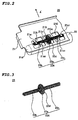
- each sheet feeding mechanism 20 includes a sheet feed roller 22 and a sheet-pressing member 23.
- the sheet feed roller 22 is coupled with a paper-feeding drive motor (not shown).
- the sheet-pressing member 23 holds the slip sheet S being transported by pressing down it on the sheet feed roller 22.
- the sheet-pressing member 23 is supported with a guide member 21 for guiding a slip sheet S.
- a coiling pin (not shown) is fixed to a predetermined position.
- One shaft portion 23b is first formed.
- pressing portion 23a larger in diameter than the shaft portion 23b, is formed in a manner that the coiling pin is gradually moved apart from the axial center of the coil, and then moved toward the axial center of the coil.
- the coiling pin is fixed at a predetermined position (the same position as the position used for forming the shaft portion 23b), and the other shaft portion 23c is formed in a similar manner.
- one shaft portion 23b of the sheet-pressing member 23 is grasped with the claw-like pieces 21a1 and 21a2, and the coupling support 21b1, while the other shaft portion 23c is grasped with the claw-like pieces 21c1 and 21c2, and the coupling support 21b2.
- the thus grasped sheet-pressing member 23, while being angularly immovable, is held with the guide member 21.
- the sheet-pressing member 23 is constructed such that the eddy-current shaped pressing portion 23a of large diameter flexibly presses the slip sheet S against the sheet feed roller.
- a spring constant of it measured in the pressing direction may be set to be small when comparing with the conventional one.
- the sheet-pressing member of the invention is capable of stably imparting an appropriate pressing force on the slip sheet S through a designer's proper selection of such factors as the effective number of turns and the diameter of the coil portion of the sheet-pressing member 23, and a material of the sheet-pressing member. In this respect, improved print quality results.
- a sheet feeding mechanism 120 as in the first embodiment, includes a sheet feed roller 122 and a sheet-pressing member 123.
- the sheet-pressing member 123 presses the slip sheet S against the sheet feed roller 122.
- the sheet-pressing member 123 is supported with a guide member 121 for guiding a slip sheet S.
- Two holes 121A and 121B are formed in the guide member 121 while being arrayed in the paper width direction.
- Claw-like pieces 121a1 and 121a2, and 121c1 and 121c2 are extended from the peripheral edges of the holes 121A and 121B.
- the claw-like pieces 121a1 and 121a2, and 121c1 and 121c2 support the side and upper portions of the sheet-pressing member 123.
- a coupling supports 121b is formed at a portion between the holes 121A and 121B.
- the sheet-pressing member 123 like the sheet-pressing member 23, includes a spring body 123A, which consists of a spring by spirally coiling a wire of stainless steel, for example.
- the pressing portions 123a and 123c are each formed like an eddy current. Those portions 123a, 123b and 123c are formed with a single wire in an integral form.
- the pressing portions 123a and 123c of the sheet-pressing member 123 are each shaped like a cone of which the apex connects to the end of the cylindrical shaft portion 123b and the bottom surface is directed outside.
- the outside diameter (diameter) of each of the pressing portions 123a and 123c is larger than that of the cylindrical shaft portion 123b.
- Contact portion 123d and 123e as the outermost circumferential edges of the pressing portions 123a and 123c are each formed with one or two wires so as to reduce a contact area where each of them contacts with the slip sheet S.
- the diameter of the pressing portion 123b is equal to the of the pressing portion 123c.
- the contact portions 123d and 123e of the pressing portions 123a and 123bc of the sheet-pressing member 123 are protruded through the holes 121A and 121B of the guide member 121 to be in contact with the sheet feed roller 122, so that the shaft portion 123b is somewhat bent.
- the fourth embodiment is a printer incorporating thereinto a sheet-pressing member constructed according to the present invention.
- Fig. 6A is a perspective view showing a printing unit of the printer of the fourth embodiment.
- Fig. 6B is a diagram showing a positional relationship between a nozzle face of a print head and a sheet-pressing member in the printer.
- the sheet-pressing members 24 and 25 may also be manufactured by a manufacturing method using an automatic coiling machine, as in the embodiments mentioned above.
- the wiper 4c is provided while being oriented at a right angle to the guide shaft 6.
- the printing unit 4 is moved along the guide shaft 6 in the opposite direction to the direction X, while at the same time the wiper 4c is moved relatively to the printing unit 4 in the direction X, and wipes ink left on the nozzle orifice array 42 of the printhead 4a.
- the sheet-pressing members 24 and 25 are oriented in a direction Y perpendicular to the guide shaft 6.
- the printer moves the slip sheet S in the direction Y while moving the printing unit 4 in the direction X.
- the slip sheet S is separated from the nozzle-orifice array 42 and pressed on the platen 10 by the pressing portions 24b, 24c and 25b, 25c, which are located in the vicinity of the nozzle-orifice array 42.
- This structural feature prevents the slip sheet S, even if it is bent, from coming in contact with the nozzle face 41. As a result, no ink is transferred to the slip sheet S, and hence a high quality print is secured.
Landscapes
- Engineering & Computer Science (AREA)
- Mechanical Engineering (AREA)
- Handling Of Cut Paper (AREA)
- Handling Of Sheets (AREA)
- Ink Jet (AREA)
- Sheets, Magazines, And Separation Thereof (AREA)
- Feeding Of Articles By Means Other Than Belts Or Rollers (AREA)
Applications Claiming Priority (4)
| Application Number | Priority Date | Filing Date | Title |
|---|---|---|---|
| JP9776198 | 1998-04-09 | ||
| JP9776198 | 1998-04-09 | ||
| JP12377198 | 1998-05-06 | ||
| JP12377198A JP3653982B2 (ja) | 1998-05-06 | 1998-05-06 | インクジェットプリンタ |
Publications (2)
| Publication Number | Publication Date |
|---|---|
| EP0949082A1 true EP0949082A1 (de) | 1999-10-13 |
| EP0949082B1 EP0949082B1 (de) | 2002-09-04 |
Family
ID=26438911
Family Applications (1)
| Application Number | Title | Priority Date | Filing Date |
|---|---|---|---|
| EP99106928A Expired - Lifetime EP0949082B1 (de) | 1998-04-09 | 1999-04-08 | Blattandrückelement für Blattzufuhr |
Country Status (6)
| Country | Link |
|---|---|
| US (1) | US6299367B1 (de) |
| EP (1) | EP0949082B1 (de) |
| KR (1) | KR100476830B1 (de) |
| CN (1) | CN1205049C (de) |
| CA (1) | CA2268471C (de) |
| DE (1) | DE69902710T2 (de) |
Families Citing this family (16)
| Publication number | Priority date | Publication date | Assignee | Title |
|---|---|---|---|---|
| US6547464B1 (en) * | 1999-12-01 | 2003-04-15 | Diebòld, Incorporated | Automated transaction machine printer |
| JP2005041202A (ja) * | 2003-07-24 | 2005-02-17 | Heidelberger Druckmas Ag | 印刷技術的な機械内で枚葉紙を搬送するための装置 |
| JP2005247546A (ja) * | 2004-03-05 | 2005-09-15 | Brother Ind Ltd | 排出ローラ、搬送装置、及びインクジェット記録装置 |
| US7309357B2 (en) * | 2004-12-30 | 2007-12-18 | Infinesse, Corporation | Prosthetic spinal discs |
| CN100551710C (zh) * | 2006-07-27 | 2009-10-21 | 研能科技股份有限公司 | 送纸机构 |
| JP4743428B2 (ja) * | 2006-08-03 | 2011-08-10 | セイコーエプソン株式会社 | 記録装置 |
| CN101312477B (zh) * | 2007-05-25 | 2010-06-02 | 东友科技股份有限公司 | 自动馈纸装置及其所适用的事务机 |
| DE102007043904A1 (de) * | 2007-09-14 | 2009-03-19 | Osram Gesellschaft mit beschränkter Haftung | Leucht-Vorrichtung |
| US20090157185A1 (en) * | 2007-12-18 | 2009-06-18 | Chong Chol Kim | Prosthetic Monolithic Spinal Discs and Method of Customizing and Constructing Discs |
| JP5444621B2 (ja) * | 2008-02-26 | 2014-03-19 | 株式会社リコー | 孔版印刷装置 |
| JP6383196B2 (ja) * | 2014-07-02 | 2018-08-29 | グラフテック株式会社 | カッティングプロッタ |
| JP6520528B2 (ja) * | 2015-07-29 | 2019-05-29 | セイコーエプソン株式会社 | 印刷装置 |
| CN108001050B (zh) * | 2016-10-28 | 2020-03-13 | 惠普发展公司有限责任合伙企业 | 调整打印介质获取 |
| JP6874703B2 (ja) * | 2018-01-31 | 2021-05-19 | ブラザー工業株式会社 | シート搬送装置 |
| JP7267774B2 (ja) * | 2019-02-28 | 2023-05-02 | キヤノン株式会社 | 画像形成装置 |
| CN110641164B (zh) * | 2019-10-24 | 2024-06-11 | 东莞市丰收实业有限公司 | 一种新型压纸装置 |
Citations (6)
| Publication number | Priority date | Publication date | Assignee | Title |
|---|---|---|---|---|
| JPH0241277A (ja) * | 1988-08-01 | 1990-02-09 | Canon Inc | インクジェットプリンタ |
| GB2285777A (en) * | 1994-01-25 | 1995-07-26 | Bride David James Mc | Spring wheel |
| GB2290262A (en) * | 1994-02-10 | 1995-12-20 | Seiko Epson Corp | Paper handling in ink jet printer. |
| JPH08133545A (ja) * | 1994-11-14 | 1996-05-28 | Ricoh Co Ltd | 紙送りローラー |
| US5534894A (en) * | 1989-09-18 | 1996-07-09 | Canon Kabushiki Kaisha | Ink jet recording medium discharging mechanism including resilently biased follower roller |
| US5558322A (en) * | 1993-06-21 | 1996-09-24 | Kabushiki Kaisha Toshiba | Paper discharge unit for use in image forming apparatus |
Family Cites Families (10)
| Publication number | Priority date | Publication date | Assignee | Title |
|---|---|---|---|---|
| US274715A (en) * | 1883-03-27 | buckley | ||
| US653155A (en) * | 1900-03-26 | 1900-07-03 | Marshall Tilden | Coil-spring. |
| US1462925A (en) * | 1921-12-12 | 1923-07-24 | Wilburger William | Spring binder post |
| US1963053A (en) * | 1933-08-14 | 1934-06-12 | Powers Spring Corp | Wire spring |
| US2852801A (en) * | 1956-08-08 | 1958-09-23 | Christian F Kleinknecht | Door stop |
| DE2506420C3 (de) * | 1975-02-15 | 1982-03-11 | Gebrüder Ahle, 5253 Lindlar | Nichtzylindrische, gewundene Druckfeder aus Draht mit kreisförmigem Querschnitt, insbesondere zur Anwendung bei Kraftfahrzeugen |
| JP2643963B2 (ja) | 1987-12-29 | 1997-08-25 | キヤノン株式会社 | プリンタの記録部材搬送装置 |
| JPH06255119A (ja) | 1993-03-09 | 1994-09-13 | Canon Inc | インクジェット記録装置 |
| JPH07101588A (ja) | 1993-10-01 | 1995-04-18 | Canon Inc | 記録装置 |
| US5868383A (en) * | 1997-03-27 | 1999-02-09 | L&P Property Management Company | Multiple rate coil spring assembly |
-
1999
- 1999-04-08 DE DE69902710T patent/DE69902710T2/de not_active Expired - Lifetime
- 1999-04-08 US US09/288,170 patent/US6299367B1/en not_active Expired - Fee Related
- 1999-04-08 EP EP99106928A patent/EP0949082B1/de not_active Expired - Lifetime
- 1999-04-08 CA CA002268471A patent/CA2268471C/en not_active Expired - Fee Related
- 1999-04-09 CN CNB99106058XA patent/CN1205049C/zh not_active Expired - Fee Related
- 1999-04-09 KR KR10-1999-0012444A patent/KR100476830B1/ko not_active Expired - Fee Related
Patent Citations (6)
| Publication number | Priority date | Publication date | Assignee | Title |
|---|---|---|---|---|
| JPH0241277A (ja) * | 1988-08-01 | 1990-02-09 | Canon Inc | インクジェットプリンタ |
| US5534894A (en) * | 1989-09-18 | 1996-07-09 | Canon Kabushiki Kaisha | Ink jet recording medium discharging mechanism including resilently biased follower roller |
| US5558322A (en) * | 1993-06-21 | 1996-09-24 | Kabushiki Kaisha Toshiba | Paper discharge unit for use in image forming apparatus |
| GB2285777A (en) * | 1994-01-25 | 1995-07-26 | Bride David James Mc | Spring wheel |
| GB2290262A (en) * | 1994-02-10 | 1995-12-20 | Seiko Epson Corp | Paper handling in ink jet printer. |
| JPH08133545A (ja) * | 1994-11-14 | 1996-05-28 | Ricoh Co Ltd | 紙送りローラー |
Non-Patent Citations (2)
| Title |
|---|
| PATENT ABSTRACTS OF JAPAN vol. 014, no. 203 (M - 0966) 25 April 1990 (1990-04-25) * |
| PATENT ABSTRACTS OF JAPAN vol. 096, no. 009 30 September 1996 (1996-09-30) * |
Also Published As
| Publication number | Publication date |
|---|---|
| DE69902710T2 (de) | 2003-08-07 |
| KR100476830B1 (ko) | 2005-03-18 |
| CA2268471A1 (en) | 1999-10-09 |
| EP0949082B1 (de) | 2002-09-04 |
| CN1235093A (zh) | 1999-11-17 |
| US6299367B1 (en) | 2001-10-09 |
| KR19990083066A (ko) | 1999-11-25 |
| CN1205049C (zh) | 2005-06-08 |
| DE69902710D1 (de) | 2002-10-10 |
| CA2268471C (en) | 2007-12-04 |
| HK1023315A1 (en) | 2000-09-08 |
Similar Documents
| Publication | Publication Date | Title |
|---|---|---|
| EP0949082B1 (de) | Blattandrückelement für Blattzufuhr | |
| US5564847A (en) | Media handling in an ink-jet printer having guide ribs | |
| US5805176A (en) | Ink jet printer and device for insuring proper printing | |
| US6089773A (en) | Print media feed system for an ink jet printer | |
| EP0927640A2 (de) | Drucker mit verbessertem Bogenführungsmechanismus | |
| US6666536B2 (en) | Ink jet device with movable platen | |
| EP0729842B1 (de) | Medientransport bei einem Tintenstrahldrucker | |
| US6890114B2 (en) | Recording apparatus | |
| US6394672B1 (en) | Imaging apparatus having a biased platen | |
| US6979080B2 (en) | Printer having improved recording medium feeding mechanism | |
| JP3922336B2 (ja) | フラップ押さえ部材及び該部材を備える記録装置 | |
| JP3812643B2 (ja) | 搬送従動ローラ取付装置 | |
| GB2290262A (en) | Paper handling in ink jet printer. | |
| US20060071422A1 (en) | Pressure roller plate with force distribution | |
| JPH05124284A (ja) | インクジエツトプリンタ | |
| JP3653982B2 (ja) | インクジェットプリンタ | |
| JPH11349178A (ja) | 紙押え部材及びこれを用いた紙送り機構並びにプリンタ | |
| KR970006746Y1 (ko) | 잉크제트 프린터의 용지 베일 장치 | |
| JPS6262782A (ja) | プリンタの用紙搬送装置 | |
| JP3379096B2 (ja) | インクジェットプリンタ | |
| JP2004091094A (ja) | 記録装置、インクジェット記録装置およびシート搬送ローラ | |
| US20080251985A1 (en) | Driven roller, transport roller device, and liquid ejecting apparatus | |
| JP3574291B2 (ja) | プリンタの紙押え機構 | |
| JPH07251971A (ja) | 用紙搬送装置 | |
| KR20040087496A (ko) | 프린터의 이송장치 |
Legal Events
| Date | Code | Title | Description |
|---|---|---|---|
| PUAI | Public reference made under article 153(3) epc to a published international application that has entered the european phase |
Free format text: ORIGINAL CODE: 0009012 |
|
| AK | Designated contracting states |
Kind code of ref document: A1 Designated state(s): CH DE FR GB IT LI |
|
| AX | Request for extension of the european patent |
Free format text: AL;LT;LV;MK;RO;SI |
|
| 17P | Request for examination filed |
Effective date: 20000330 |
|
| AKX | Designation fees paid |
Free format text: CH DE FR GB IT LI |
|
| 17Q | First examination report despatched |
Effective date: 20001005 |
|
| GRAG | Despatch of communication of intention to grant |
Free format text: ORIGINAL CODE: EPIDOS AGRA |
|
| GRAG | Despatch of communication of intention to grant |
Free format text: ORIGINAL CODE: EPIDOS AGRA |
|
| GRAH | Despatch of communication of intention to grant a patent |
Free format text: ORIGINAL CODE: EPIDOS IGRA |
|
| GRAH | Despatch of communication of intention to grant a patent |
Free format text: ORIGINAL CODE: EPIDOS IGRA |
|
| GRAA | (expected) grant |
Free format text: ORIGINAL CODE: 0009210 |
|
| AK | Designated contracting states |
Kind code of ref document: B1 Designated state(s): CH DE FR GB IT LI |
|
| REG | Reference to a national code |
Ref country code: GB Ref legal event code: FG4D |
|
| REG | Reference to a national code |
Ref country code: CH Ref legal event code: EP |
|
| REG | Reference to a national code |
Ref country code: CH Ref legal event code: NV Representative=s name: BOVARD AG PATENTANWAELTE |
|
| REF | Corresponds to: |
Ref document number: 69902710 Country of ref document: DE Date of ref document: 20021010 |
|
| ET | Fr: translation filed | ||
| PLBE | No opposition filed within time limit |
Free format text: ORIGINAL CODE: 0009261 |
|
| STAA | Information on the status of an ep patent application or granted ep patent |
Free format text: STATUS: NO OPPOSITION FILED WITHIN TIME LIMIT |
|
| 26N | No opposition filed |
Effective date: 20030605 |
|
| PGFP | Annual fee paid to national office [announced via postgrant information from national office to epo] |
Ref country code: CH Payment date: 20100414 Year of fee payment: 12 |
|
| REG | Reference to a national code |
Ref country code: CH Ref legal event code: PFA Owner name: SEIKO EPSON CORPORATION Free format text: SEIKO EPSON CORPORATION#4-1, NISHISHINJUKU 2-CHOME#SHINJUKU-KU, TOKYO 163-0811 (JP) -TRANSFER TO- SEIKO EPSON CORPORATION#4-1, NISHISHINJUKU 2-CHOME#SHINJUKU-KU, TOKYO 163-0811 (JP) |
|
| PGFP | Annual fee paid to national office [announced via postgrant information from national office to epo] |
Ref country code: FR Payment date: 20110426 Year of fee payment: 13 Ref country code: DE Payment date: 20110406 Year of fee payment: 13 |
|
| PGFP | Annual fee paid to national office [announced via postgrant information from national office to epo] |
Ref country code: GB Payment date: 20110406 Year of fee payment: 13 |
|
| PGFP | Annual fee paid to national office [announced via postgrant information from national office to epo] |
Ref country code: IT Payment date: 20110418 Year of fee payment: 13 |
|
| REG | Reference to a national code |
Ref country code: CH Ref legal event code: PL |
|
| PG25 | Lapsed in a contracting state [announced via postgrant information from national office to epo] |
Ref country code: LI Free format text: LAPSE BECAUSE OF NON-PAYMENT OF DUE FEES Effective date: 20110430 Ref country code: CH Free format text: LAPSE BECAUSE OF NON-PAYMENT OF DUE FEES Effective date: 20110430 |
|
| GBPC | Gb: european patent ceased through non-payment of renewal fee |
Effective date: 20120408 |
|
| REG | Reference to a national code |
Ref country code: FR Ref legal event code: ST Effective date: 20121228 |
|
| PG25 | Lapsed in a contracting state [announced via postgrant information from national office to epo] |
Ref country code: GB Free format text: LAPSE BECAUSE OF NON-PAYMENT OF DUE FEES Effective date: 20120408 |
|
| REG | Reference to a national code |
Ref country code: DE Ref legal event code: R119 Ref document number: 69902710 Country of ref document: DE Effective date: 20121101 |
|
| PG25 | Lapsed in a contracting state [announced via postgrant information from national office to epo] |
Ref country code: IT Free format text: LAPSE BECAUSE OF NON-PAYMENT OF DUE FEES Effective date: 20120408 Ref country code: FR Free format text: LAPSE BECAUSE OF NON-PAYMENT OF DUE FEES Effective date: 20120430 |
|
| PG25 | Lapsed in a contracting state [announced via postgrant information from national office to epo] |
Ref country code: DE Free format text: LAPSE BECAUSE OF NON-PAYMENT OF DUE FEES Effective date: 20121101 |