EP0950438A1 - Verfahren zum Aufbringen eines Musters auf eine Oberfläche eines Trägers - Google Patents
Verfahren zum Aufbringen eines Musters auf eine Oberfläche eines Trägers Download PDFInfo
- Publication number
- EP0950438A1 EP0950438A1 EP98105042A EP98105042A EP0950438A1 EP 0950438 A1 EP0950438 A1 EP 0950438A1 EP 98105042 A EP98105042 A EP 98105042A EP 98105042 A EP98105042 A EP 98105042A EP 0950438 A1 EP0950438 A1 EP 0950438A1
- Authority
- EP
- European Patent Office
- Prior art keywords
- pattern
- rows
- output channels
- channels
- sample
- Prior art date
- Legal status (The legal status is an assumption and is not a legal conclusion. Google has not performed a legal analysis and makes no representation as to the accuracy of the status listed.)
- Withdrawn
Links
- 238000000034 method Methods 0.000 title claims description 25
- 239000000758 substrate Substances 0.000 title abstract 3
- 238000005507 spraying Methods 0.000 claims abstract description 8
- 238000006073 displacement reaction Methods 0.000 claims abstract description 7
- 238000001035 drying Methods 0.000 claims abstract description 3
- 239000000976 ink Substances 0.000 claims abstract description 3
- 239000007921 spray Substances 0.000 claims description 52
- 239000007788 liquid Substances 0.000 claims description 18
- 230000008021 deposition Effects 0.000 abstract description 3
- 238000000151 deposition Methods 0.000 abstract 3
- 239000012530 fluid Substances 0.000 abstract 3
- 238000005286 illumination Methods 0.000 abstract 1
- 230000000149 penetrating effect Effects 0.000 abstract 1
- 238000004519 manufacturing process Methods 0.000 description 2
- 230000009286 beneficial effect Effects 0.000 description 1
- 238000007796 conventional method Methods 0.000 description 1
- 238000013461 design Methods 0.000 description 1
- 238000011161 development Methods 0.000 description 1
- 230000018109 developmental process Effects 0.000 description 1
- 229920001971 elastomer Polymers 0.000 description 1
- 239000000806 elastomer Substances 0.000 description 1
- ZINJLDJMHCUBIP-UHFFFAOYSA-N ethametsulfuron-methyl Chemical compound CCOC1=NC(NC)=NC(NC(=O)NS(=O)(=O)C=2C(=CC=CC=2)C(=O)OC)=N1 ZINJLDJMHCUBIP-UHFFFAOYSA-N 0.000 description 1
- 230000008020 evaporation Effects 0.000 description 1
- 238000001704 evaporation Methods 0.000 description 1
- 239000003973 paint Substances 0.000 description 1
- 238000012545 processing Methods 0.000 description 1
Images

Classifications
-
- B—PERFORMING OPERATIONS; TRANSPORTING
- B05—SPRAYING OR ATOMISING IN GENERAL; APPLYING FLUENT MATERIALS TO SURFACES, IN GENERAL
- B05D—PROCESSES FOR APPLYING FLUENT MATERIALS TO SURFACES, IN GENERAL
- B05D5/00—Processes for applying liquids or other fluent materials to surfaces to obtain special surface effects, finishes or structures
- B05D5/06—Processes for applying liquids or other fluent materials to surfaces to obtain special surface effects, finishes or structures to obtain multicolour or other optical effects
-
- B—PERFORMING OPERATIONS; TRANSPORTING
- B05—SPRAYING OR ATOMISING IN GENERAL; APPLYING FLUENT MATERIALS TO SURFACES, IN GENERAL
- B05D—PROCESSES FOR APPLYING FLUENT MATERIALS TO SURFACES, IN GENERAL
- B05D1/00—Processes for applying liquids or other fluent materials
- B05D1/002—Processes for applying liquids or other fluent materials the substrate being rotated
-
- B—PERFORMING OPERATIONS; TRANSPORTING
- B05—SPRAYING OR ATOMISING IN GENERAL; APPLYING FLUENT MATERIALS TO SURFACES, IN GENERAL
- B05D—PROCESSES FOR APPLYING FLUENT MATERIALS TO SURFACES, IN GENERAL
- B05D1/00—Processes for applying liquids or other fluent materials
- B05D1/26—Processes for applying liquids or other fluent materials performed by applying the liquid or other fluent material from an outlet device in contact with, or almost in contact with, the surface
Definitions
- the invention relates to a method for applying a pattern to a Surface of a carrier with at least two output channels parallel rows of samples are applied.
- Such methods of applying a pattern are among others used in the production of stencils.
- a blank is sprayed on with the help of spray nozzles, which are the output channels form.
- the spray nozzles are operated by a central processing unit controlled so that the covering liquid according to the sprayed pattern to be generated.
- the spray head After applying a sample section, the spray head is around the Distance between the first and the last spray nozzle shifted by to generate the next pattern section in the manner described.
- each pattern row generated by a spray nozzle characteristic properties based on those of a series of samples are different, which was generated by another spray nozzle.
- all sample rows of a sample strip are from one and the same Spray nozzle were generated, they also have the corresponding characteristics, which is more visible through this repetition.
- connection point between the individual is particularly problematic Sample sections, because the differences in spray heads with several spray nozzles of the individual nozzles are such that they come from a spray nozzle to the neighboring are not very strong, but differ from one end of the Increase the spray head to the other. So that is typical the difference between the first and the last spray nozzle is greatest. Now that in the connection area of the sample sections of the first Spray nozzle generated pattern strips immediately on one of the last Spray nozzle strikes generated sample strips, make themselves there Differences are particularly noticeable.
- the object of the invention is another Process for applying a pattern to a surface of a support To provide, in particular, patterns without visible Get errors generated.
- the output channels and the pattern rows so displaced relative to each other in their transverse direction be that at least with a part of the output channels optional series of patterns can be applied to get a complete pattern where the individual applied with different output channels Sample rows optionally side by side with each other are mixed.
- the output channels are together by one Pattern row spacing or a multiple thereof, at most, however, by the distance between measured in the direction of displacement the first and last output channels, the output channels can be moved together by the same distance.
- the output channels can be moved together by the same distance.
- the position of an output channel and the already generated sample series are determined whether the considered output channel should create a pattern row in this position or not.
- the pattern row is already applied in the desired shape was or if a control program for applying the pattern decides that the series of samples in question will later be from another Output channel is generated.
- the feed is preferably equal to the product is the sample row spacing and the number of output channels, where each with all output channels located above the sample area be applied.
- the pattern rows can be placed on a circular cylindrical surface also be applied in the longitudinal direction of the cylinder, while the cylindrical Carrier is fixed and after applying a sample set is rotated to generate the feed.
- An advantageous embodiment of the invention is characterized in that that the pattern rows on a circular cylindrical surface essentially are applied in the circumferential direction, the in the cylinder longitudinal direction output channels offset from each other together to be moved in the longitudinal direction of the cylinder. It is advisable if the output channels during the application of the pattern rows are recorded and the shift of the output channels each after the application of one or a group of sample series, before the next or the following group of pattern series is applied becomes.
- the control program can be in this embodiment make the invention particularly simple.
- the output channels during the application of one or a group of pattern rows across continuously shifted to the sample series by the specified distance are continuously shifted to the sample series by the specified distance.
- the cylindrical surface, to which the pattern is to be applied for example as in In the case of cylindrical or roller-shaped printing forms, completely extend around the cylinder, but it is also conceivable that a itself flat but flexible carrier clamped on a cylindrical roller to create a pattern.
- the pattern is exposed by exposing one photosensitive layer is applied by means of laser light.
- the pattern by removing a spot the layer provided on the carrier is applied by means of laser light.
- the method according to the invention can be used particularly expediently if the pattern is applied by spraying on a covering liquid Spray nozzles is applied, with an opaque covering liquid is sprayed onto a photosensitive layer.
- Another embodiment of the invention is characterized in that an electrically insulating cover liquid on a continuous conductive Surface is sprayed on. It is also possible according to the invention that the carrier is a sieve, onto which a covering liquid is sprayed is that after drying and / or curing mechanically and is chemically resistant to printing inks.
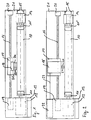
- the device shown in Figure 1 for applying a pattern the surface of a cylinder 10 provided as a carrier has two receiving cones 11, 11 ', between which the cylinder 10 is clamped.
- the receiving cone 11 on the left in FIG. 1 has a main drive 12 connected, which is arranged in a corresponding housing 13, the Operating elements for the device in a manner not shown has on its front.
- the other receiving cone 11 ' is open a carriage 14 attached to the cylinder in the longitudinal direction on rails 15 is detectably displaceable to clamp cylinders 10 of different lengths to be able to.
- Cylinder 10 is a lead and drive spindle 16, hereinafter briefly referred to as a spindle, arranged for a support slide 17, on the spray head 18 as a dispensing head with a plurality of dispensing channels D1, D2, ... Dn serving spray nozzles is arranged.
- the spindle 16 is at one end with connected to a spindle drive 19, while its other end via one corresponding bearing block 20 supported on a machine frame 21 is.
- Figure 2 shows another device from applying a pattern to one Surface of a cylinder 10, which differs from that of Figure 1 essentially only differs in that they are not covered with a covering liquid but works with laser light.
- the device 2 shows a laser 22 arranged in the housing 13, which has a to the longitudinal direction of the spindle 16 parallel laser beam 23 to a laser output head 18 'transmits that on the one carried by the spindle 16 Carriage 17 is arranged.
- the laser output head 18 'points in not shown a split optics for duplicating the Laser beam 23 on the in several mutually independent beams L1, ... Ln can be switched.
- the split optics thus comprises several parallel output channels through which a laser beam L1, ... Ln to each Applying a pattern to the surface of the cylinder 10 directed thereon becomes.
- the nozzles D1 to D4 create an opaque or electrically insulating covering liquid according to the pattern sprayed on the cylinder 10.
- the cylinder 10 is driven by the main drive rotated around its longitudinal axis at a precisely defined speed.
- the Nozzle D1 applied the first series of samples M1.
- the spraying of the covering liquid takes place according to the individual sample points the sample series.
- the other nozzles D2 to D4 are switched off with the aid of the nozzle D1.
- the spray head 18 is moved by the feed V from position a to position b, in which the first two nozzles D1 and D2 lie over the surface to be provided with the pattern.
- the feed V i.e. the distance between the positions a and b, by which the spray head 18 is displaced, is equal to the product of the distance a R between the individual pattern rows Mi and the number n K of the dispensing channels, that is to say the number of spray nozzles in the present case.
- the distance between the individual spray nozzles D1 to D4 is preferably an integer multiple including 1 of the pattern row spacing a R smaller than the feed. This condition is particularly expedient if a large number of, for example, fifty, one hundred or more dispensing channels is provided on an dispensing head is.
- the feed is significantly smaller than the channel spacing.
- the distance a K of the nozzles from one another in the cylinder longitudinal direction is smaller by a pattern row spacing a R than the feed rate V.
- the two pattern rows M2 and M5 are applied in the position b of the spray head 18.
- the spray head 18 is then moved into the position c, in which the pattern rows M9, M6 and M3 are generated by the spray nozzles D1, D2 and D3, while the spray nozzle D4 is still switched off.
- the pattern rows M13, M10, M7 and M4 are then applied in position d by means of the nozzles D1, D2, D3 and D4.
- the solid lines in FIG. 3 thus represent completely applied rows of samples and illustrate the situation after application the pattern series Mi in the position e of the spray head 18 and before moving to the next position. Then in the following position the lines M12, M15, M18 and M21 are generated. So you can see that the individual Pattern series Mi between two pattern series M (i-1), M (i + 1) lie, which were generated by other spray nozzles Di.
- the pattern series Mi represent circumferential lines of the cylinder 10, which when the the area to be patterned completely around the cylinder 10 extends, are also self-contained.
- the pattern series Mi result in a multiplicity of helical lines lying next to one another.
- the output channels in the x direction are arranged side by side while the individual rows of patterns
- the output channels can be applied in the y direction move in the y direction over the flat beam while their position is maintained in the x direction.
- the output channels are then in the from Control program predetermined way preferably shifted in the x direction, in order to then move the to generate the next series of samples.
- the described mode of operation of the method according to the invention is when applying a pattern to a support always the same regardless whether with a covering liquid, with laser light for exposure or removing layers or with other suitable surface Way structuring means is worked.
- a sensible resolution and a sensible pattern row spacing is determined for a specific pattern, taking into account the quality and the desired output performance. It should be noted, however, that a certain ratio must be maintained between the number n K of the output channels and the pattern row spacing a R in order to be able to use the method according to the invention. Since the distance a K between the individual output channels across the pattern rows Mi is generally an unchangeable variable for a particular output head, only the pattern row spacing a R and the number n K of the output channels used can be varied.
- a R a K / n , where n is an integer.
- the pattern row spacing a R i.e. the resolution 1 / a R of the pattern in the direction transverse to the pattern rows, and the number of active output channels n K can be varied in order to optimally match the desired one Pattern to be adapted.
- the pattern row spacing a R can be predetermined according to the respective requirements.
- the channel spacing a K is then an integer multiple of the pattern row spacing.
Landscapes
- Manufacturing Of Printed Wiring (AREA)
- Application Of Or Painting With Fluid Materials (AREA)
Abstract
Description
Claims (14)
- Verfahren zum Aufbringen eines Musters auf eine Oberfläche eines Trägers (10), bei dem mit wenigstens zwei Ausgabekanälen (D1, D2, ...) zueinander parallele Musterreihen (M1, M2, ...) aufgebracht werden, dadurch gekennzeichnet, daß die Ausgabekanäle (D1, D2, ...) und die Musterreihen (M1, M2, ...) in deren Querrichtung relativ zueinander jeweils so verschoben werden, daß zumindest mit einem Teil der Ausgabekanäle (D1, D2, ...) wahlweise Musterreihen (M1, M2, ...) aufgebracht werden können, um ein vollständiges Muster zu erhalten, bei dem die einzelnen mit unterschiedlichen Ausgabekanälen (D1, D2, ...) aufgebrachten Musterreihen (M1, M2, ...) wahlweise nebeneinanderliegend miteinander vermischt sind.
- Verfahren nach Anspruch 1, dadurch gekennzeichnet, daß die Ausgabekanäle (D1, D2, ...) gemeinsam um einen Musterreihenabstand (aR) oder ein Vielfaches davon verschoben werden, höchstens jedoch um den in Verschieberichtung gemessenen Abstand zwischen dem ersten und dem letzten Ausgabekanal (D1 bzw. Dn).
- Verfahren nach Anspruch 1 oder 2, dadurch gekennzeichnet, daß die Ausgabekanäle (D1, D2, ...) jeweils gemeinsam um den gleichen Abstand (Vorschub V) verschoben werden.
- Verfahren nach Anspruch 3, dadurch gekennzeichnet, daß der Vorschub (V) vorzugsweise gleich dem Produkt aus Musterreihenabstand (aR) und Anzahl (nK) der Ausgabekanäle (D1, D2, ...) ist.
- Verfahren nach Anspruch 4, dadurch gekennzeichnet, daß jeweils mit allen über der Musterfläche befindlichen Ausgabekanälen (D1, D2, ...) Musterreihen (M1, M2, ...) aufgebracht werden.
- Verfahren nach einem der vorstehenden Ansprüche, dadurch gekennzeichnet, daß die Musterreihen (M1, M2, ...) auf eine kreiszylindrische Oberfläche im wesentlichen in Umfangsrichtung aufgebracht werden, wobei die in Zylinderlängsrichtung gegeneinander versetzt angeordneten Ausgabekanäle (D1, D2, ...) gemeinsam in Zylinderlängsrichtung verschoben werden.
- Verfahren nach Anspruch 6, dadurch gekennzeichnet, daß die Ausgabekanäle (D1, D2, ...) während des Aufbringens der Musterreihen (M1, M2, ...) festgehalten werden und die Verschiebung der Ausgabekanäle (D1, D2, ...) jeweils nach dem Aufbringen einer oder einer Gruppe von Musterreihen (M1, M2, ...) erfolgt, bevor die nächste oder die folgende Gruppe von Musterreihen (M1, M2, ...) aufgebracht wird.
- Verfahren nach Anspruch 6, dadurch gekennzeichnet, daß die Ausgabekanäle (D1, D2, ...) während des Aufbringens einer oder einer Gruppe von Musterreihen (M1, M2, ...) kontinuierlich um den vorgegebenen Abstand (Vorschub V) verschoben werden.
- Verfahren nach einem der vorstehenden Ansprüche, dadurch gekennzeichnet, daß das Muster durch Belichten einer photoempfindlichen Schicht mittels Laserlicht aufgebracht wird.
- Verfahren nach Anspruch 1 bis 8, dadurch gekennzeichnet, daß das Muster durch punktuelles Entfernen einer auf dem Träger (10) vorgesehenen Schicht mittels Laserlichts aufgebracht wird.
- Verfahren nach Anspruch 1 bis 8, dadurch gekennzeichnet, daß das Muster durch Aufspritzen einer Abdeckflüssigkeit mittels Spritzdüsen (D1, D2, ...) aufgebracht wird.
- Verfahren nach Anspruch 11, dadurch gekennzeichnet, daß eine lichtundurchlässige Abdeckflüssigkeit auf eine photoempfindliche Schicht aufgespritzt wird.
- Verfahren nach Anspruch 11, dadurch gekennzeichnet, daß eine elektrisch isolierende Abdeckflüssigkeit auf eine durchgehende leitende Oberfläche aufgespritzt wird.
- Verfahren nach Anspruch 11, dadurch gekennzeichnet, daß der Träger (10) ein Sieb ist, auf das eine Abdeckflüssigkeit aufgespritzt wird, die nach dem Trocknen und/oder Aushärten mechanisch und chemisch gegen Druckfarben widerstandsfähig ist.
Priority Applications (2)
| Application Number | Priority Date | Filing Date | Title |
|---|---|---|---|
| EP98105042A EP0950438A1 (de) | 1998-03-19 | 1998-03-19 | Verfahren zum Aufbringen eines Musters auf eine Oberfläche eines Trägers |
| US09/272,254 US6083571A (en) | 1998-03-19 | 1999-03-19 | Method of applying a pattern to a surface of a substrate |
Applications Claiming Priority (1)
| Application Number | Priority Date | Filing Date | Title |
|---|---|---|---|
| EP98105042A EP0950438A1 (de) | 1998-03-19 | 1998-03-19 | Verfahren zum Aufbringen eines Musters auf eine Oberfläche eines Trägers |
Publications (1)
| Publication Number | Publication Date |
|---|---|
| EP0950438A1 true EP0950438A1 (de) | 1999-10-20 |
Family
ID=8231623
Family Applications (1)
| Application Number | Title | Priority Date | Filing Date |
|---|---|---|---|
| EP98105042A Withdrawn EP0950438A1 (de) | 1998-03-19 | 1998-03-19 | Verfahren zum Aufbringen eines Musters auf eine Oberfläche eines Trägers |
Country Status (2)
| Country | Link |
|---|---|
| US (1) | US6083571A (de) |
| EP (1) | EP0950438A1 (de) |
Families Citing this family (4)
| Publication number | Priority date | Publication date | Assignee | Title |
|---|---|---|---|---|
| US6485889B1 (en) * | 1999-09-15 | 2002-11-26 | Agfa-Gevaert | Method for obtaining a heat sensitive element by spray-coating |
| US7220329B2 (en) * | 2003-03-20 | 2007-05-22 | National Gypsum Properties, Llc | Method for applying reference markings to wallboard during manufacture |
| JP4294360B2 (ja) * | 2003-04-11 | 2009-07-08 | 大日本スクリーン製造株式会社 | ニス塗布方法、ニス塗布装置および印刷機 |
| JP6206914B2 (ja) * | 2013-10-21 | 2017-10-04 | 国立研究開発法人産業技術総合研究所 | 撥液性表面の形成方法 |
Citations (9)
| Publication number | Priority date | Publication date | Assignee | Title |
|---|---|---|---|---|
| BE422560A (de) * | ||||
| DE2804539A1 (de) * | 1978-02-03 | 1979-08-16 | Pusch Guenter | Automatisiertes farbspritzverfahren |
| EP0056704A2 (de) * | 1981-01-21 | 1982-07-28 | Alcan International Limited | Vorrichtung und Verfahren zum Aufbringen eines Überzuges |
| FR2641717A1 (fr) * | 1989-01-19 | 1990-07-20 | Navarra Componentes Electronic | Procede continu de depot d'une substance sur une bande support et machine pour la mise en oeuvre de ce procede |
| GB2282771A (en) * | 1993-10-15 | 1995-04-19 | Fuji Electric Co Ltd | Resin impregnating clutch plates or brake pads by ejection of impregnant from a nozzle |
| CH687742A5 (de) * | 1992-05-20 | 1997-02-14 | Lonza Ag Gampel Wallis Geschof | Verfahren und Vorrichtung zum Aufbringen einer Beschichtung auf einen Koerper mit einer zylindrischen Oberflaeche. |
| EP0765694A1 (de) * | 1995-09-22 | 1997-04-02 | Dai Nippon Printing Co., Ltd. | Verfahren und Anlage zum Düsebeschichten |
| US5662968A (en) * | 1995-07-24 | 1997-09-02 | Nichiha Corporation | Method of painting building board by spray painting apparatus |
| US5707689A (en) * | 1995-11-29 | 1998-01-13 | Nichiha Corporation | Method of painting building boards |
Family Cites Families (2)
| Publication number | Priority date | Publication date | Assignee | Title |
|---|---|---|---|---|
| JPH0615068B2 (ja) * | 1988-09-05 | 1994-03-02 | 本田技研工業株式会社 | 自動車車体の塗装方法 |
| US5373137A (en) * | 1994-01-28 | 1994-12-13 | Litton Systems, Inc. | Multiple-line laser writing apparatus and method |
-
1998
- 1998-03-19 EP EP98105042A patent/EP0950438A1/de not_active Withdrawn
-
1999
- 1999-03-19 US US09/272,254 patent/US6083571A/en not_active Expired - Fee Related
Patent Citations (9)
| Publication number | Priority date | Publication date | Assignee | Title |
|---|---|---|---|---|
| BE422560A (de) * | ||||
| DE2804539A1 (de) * | 1978-02-03 | 1979-08-16 | Pusch Guenter | Automatisiertes farbspritzverfahren |
| EP0056704A2 (de) * | 1981-01-21 | 1982-07-28 | Alcan International Limited | Vorrichtung und Verfahren zum Aufbringen eines Überzuges |
| FR2641717A1 (fr) * | 1989-01-19 | 1990-07-20 | Navarra Componentes Electronic | Procede continu de depot d'une substance sur une bande support et machine pour la mise en oeuvre de ce procede |
| CH687742A5 (de) * | 1992-05-20 | 1997-02-14 | Lonza Ag Gampel Wallis Geschof | Verfahren und Vorrichtung zum Aufbringen einer Beschichtung auf einen Koerper mit einer zylindrischen Oberflaeche. |
| GB2282771A (en) * | 1993-10-15 | 1995-04-19 | Fuji Electric Co Ltd | Resin impregnating clutch plates or brake pads by ejection of impregnant from a nozzle |
| US5662968A (en) * | 1995-07-24 | 1997-09-02 | Nichiha Corporation | Method of painting building board by spray painting apparatus |
| EP0765694A1 (de) * | 1995-09-22 | 1997-04-02 | Dai Nippon Printing Co., Ltd. | Verfahren und Anlage zum Düsebeschichten |
| US5707689A (en) * | 1995-11-29 | 1998-01-13 | Nichiha Corporation | Method of painting building boards |
Also Published As
| Publication number | Publication date |
|---|---|
| US6083571A (en) | 2000-07-04 |
Similar Documents
| Publication | Publication Date | Title |
|---|---|---|
| DE69403520T2 (de) | Herstellungsverfahren eines seitenbreitigen piezo-elektrischen Farbstrahldruckkopfes | |
| DE2918283C2 (de) | Gerät zur Substratbehandlung mit einem Drehspiegel od. dgl. | |
| EP0396099B1 (de) | Anordnung zum Abtragen von Material eines Targets | |
| DE69113924T2 (de) | Gravierverfahren von Gegenständen in fester Form und die hergestellten Gegenstände. | |
| EP1473154A2 (de) | Druckverfahren und Druckmaschine | |
| EP0135700A2 (de) | Verfahren zum Einstellen des Farbwerks einer Druckmaschine | |
| EP1990206A2 (de) | Verfahren und Vorrichtung zum Bedrucken eines Bauteils mit zwei zueinander geneigten Oberflächenbereichen mittels eines digitalen Druckverfahrens | |
| DE102012006558B4 (de) | Verfahren zur Herstellung einer Flexodruckform | |
| EP0486855A1 (de) | Rasterwalze | |
| EP1033245B1 (de) | Sprühfeuchtwerk mit hoher effektiver Sprühfrequenz | |
| DE102020107294A1 (de) | Verfahren zur Kalibrierung von Inkjet-Düsen in einer Druckvorrichtung und eine Druckvorrichtung zum Betrieb mit einem solchen Verfahren | |
| DE60127642T2 (de) | Vorrichtung zum Bilden einer Düse in einem Element eines Tintenstrahldruckkopfes, Düsenelement, mit solchem Düsenelement versehener Tintenstrahldruckkopf und mit solchem Druckkopf versehener Tintenstrahldrucker | |
| DE3311237A1 (de) | Verfahren und vorrichtung zur herstellung einer druckform | |
| DE69912159T2 (de) | System und Verfahren zur Kompensation der Eigenschaft einer durch Ablation hergestellten Düsenplatte eines Tintenstrahldruckers | |
| EP1040916B1 (de) | Verfahren und Vorrichtung eines Druckwerkzeugs | |
| EP1245326B1 (de) | Verfahren zum Betreiben einer Lasergravureinrichtung | |
| EP0435058A2 (de) | Schichtübertragungsverfahren zur Bilderzeugung und Vorrichtung zur Durchführung des Verfahrens | |
| EP3547221B1 (de) | Verfahren zum bedrucken der oberfläche eines objekts | |
| EP3482937A1 (de) | Verfahren zum strukturieren einer oberfläche, tiefdruckform oder prägewerkzeug sowie verwendung | |
| US6083571A (en) | Method of applying a pattern to a surface of a substrate | |
| WO2002040278A1 (de) | Druckvorrichtungen mit einer mehrzahl von druckköpfen | |
| EP0802049A1 (de) | Halbton-Druckverfahren und Druckmaschine zu seiner Durchführung | |
| EP2601821B1 (de) | Siebdruckmaschine und siebdruckverfahren zur herstellung von platinen für die elektroindustrie | |
| DE3823742C2 (de) | ||
| EP1333984B1 (de) | Druckvorrichtung |
Legal Events
| Date | Code | Title | Description |
|---|---|---|---|
| PUAI | Public reference made under article 153(3) epc to a published international application that has entered the european phase |
Free format text: ORIGINAL CODE: 0009012 |
|
| 17P | Request for examination filed |
Effective date: 19990127 |
|
| AK | Designated contracting states |
Kind code of ref document: A1 Designated state(s): AT CH DE ES FR GB IT LI NL |
|
| AX | Request for extension of the european patent |
Free format text: AL;LT;LV;MK;RO;SI |
|
| AKX | Designation fees paid |
Free format text: AT CH DE ES FR GB IT LI NL |
|
| 17Q | First examination report despatched |
Effective date: 20000620 |
|
| GRAG | Despatch of communication of intention to grant |
Free format text: ORIGINAL CODE: EPIDOS AGRA |
|
| GRAG | Despatch of communication of intention to grant |
Free format text: ORIGINAL CODE: EPIDOS AGRA |
|
| GRAH | Despatch of communication of intention to grant a patent |
Free format text: ORIGINAL CODE: EPIDOS IGRA |
|
| GRAH | Despatch of communication of intention to grant a patent |
Free format text: ORIGINAL CODE: EPIDOS IGRA |
|
| STAA | Information on the status of an ep patent application or granted ep patent |
Free format text: STATUS: THE APPLICATION IS DEEMED TO BE WITHDRAWN |
|
| 18D | Application deemed to be withdrawn |
Effective date: 20021001 |