EP0950867A2 - Klimaanlage - Google Patents
Klimaanlage Download PDFInfo
- Publication number
- EP0950867A2 EP0950867A2 EP99301781A EP99301781A EP0950867A2 EP 0950867 A2 EP0950867 A2 EP 0950867A2 EP 99301781 A EP99301781 A EP 99301781A EP 99301781 A EP99301781 A EP 99301781A EP 0950867 A2 EP0950867 A2 EP 0950867A2
- Authority
- EP
- European Patent Office
- Prior art keywords
- wind directing
- air conditioner
- motor
- corner portion
- conditioner according
- Prior art date
- Legal status (The legal status is an assumption and is not a legal conclusion. Google has not performed a legal analysis and makes no representation as to the accuracy of the status listed.)
- Granted
Links
Images


Classifications
-
- F—MECHANICAL ENGINEERING; LIGHTING; HEATING; WEAPONS; BLASTING
- F24—HEATING; RANGES; VENTILATING
- F24F—AIR-CONDITIONING; AIR-HUMIDIFICATION; VENTILATION; USE OF AIR CURRENTS FOR SCREENING
- F24F1/00—Room units for air-conditioning, e.g. separate or self-contained units or units receiving primary air from a central station
- F24F1/0007—Indoor units, e.g. fan coil units
- F24F1/0011—Indoor units, e.g. fan coil units characterised by air outlets
-
- F—MECHANICAL ENGINEERING; LIGHTING; HEATING; WEAPONS; BLASTING
- F24—HEATING; RANGES; VENTILATING
- F24F—AIR-CONDITIONING; AIR-HUMIDIFICATION; VENTILATION; USE OF AIR CURRENTS FOR SCREENING
- F24F13/00—Details common to, or for air-conditioning, air-humidification, ventilation or use of air currents for screening
-
- F—MECHANICAL ENGINEERING; LIGHTING; HEATING; WEAPONS; BLASTING
- F24—HEATING; RANGES; VENTILATING
- F24F—AIR-CONDITIONING; AIR-HUMIDIFICATION; VENTILATION; USE OF AIR CURRENTS FOR SCREENING
- F24F1/00—Room units for air-conditioning, e.g. separate or self-contained units or units receiving primary air from a central station
- F24F1/0007—Indoor units, e.g. fan coil units
- F24F1/0043—Indoor units, e.g. fan coil units characterised by mounting arrangements
- F24F1/0047—Indoor units, e.g. fan coil units characterised by mounting arrangements mounted in the ceiling or at the ceiling
Definitions
- the present invention is also characterized by the aforementioned motor cover being provided with a motor mounting pedestal having a shaft insertion hole, and a cam gear housing recess having a cut-out portion at the part thereof facing the aforementioned motor mounting pedestal with a rotational shaft of the aforementioned cam gear being vertically provided at the center thereof, with the aforementioned motor being mounted on the inside surface of the aforementioned motor mounting pedestal with the output shaft thereof being inserted through the aforementioned shaft insertion hole, and with the aforementioned output gear being mounted onto the output shaft of the aforementioned motor on the outside surface of the aforementioned motor mounting pedestal and being meshed with the aforementioned cam gear, which is in the aforementioned cam gear housing recess, in the aforementioned cut-out portion.
- the present invention is characterized by a rib plate having a U-shaped shaft bearing slot for holding the rotational shaft of the aforementioned wind directing plate being formed at the aforementioned front panel, and characterized by a sleeve bush for engaging in the aforementioned shaft bearing slot being integrally formed at a joint member of the aforementioned universal joint attached to the aforementioned rotational shaft.
- only one spring acting on a universal joint as a coupling means for coupling the aforementioned wind directing plates in each of the corner portions is applied for each of the aforementioned second spring means disposed on the aforementioned second and third corner portions.
- a main body housing embedded in a ceiling is also included, and there is no difference in the main body housing from that in the conventional art explained above, therefore the explanation will be omitted.
- those which are the same, or considered to be the same as in the conventional embodiment explained above are given the same reference numerals and signs as those in the conventional embodiment.
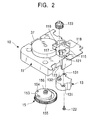
- the wind directing plate driving means 10 is also provided on a predetermined corner portion 3a of the front panel 3 in the present invention, and in this case, the wind directing plate driving means 10, which has been previously assembled in a different place, is mounted on the front panel 3.
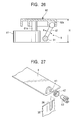
- a motor mounting pedestal 115 is formed on the parts mounting base plate 110 to be adjacent to the cam gear housing recess 112. Looking at the condition in Fig. 3, the motor mounting pedestal 115 is raised higher than the parts mounting base plate 110.
- a fall-off prevention hook 121 for an output shaft 133 attached to the motor 13 is provided on the outer face side (bottom face side in Fig. 3) of the motor mounting pedestal 115 in Fig. 2.
- the fall-off prevention hook 121 consists of an inverted L-shaped hook having a height a little higher than the thickness of the output gear 133, and is disposed at one side of the shaft insertion hole 118 and near the cam gear housing recess 112.
- the motor cover 11 is turned upside down, and the cam gear 15 is inserted into the cam gear housing recess 112. Specifically, with the portion without teeth 151 of the cam gear 15 facing the end portion 117 of the motor mounting pedestal 115, the shaft hole 156 is slid onto the rotational shaft 113, and the cam gear 15 is slipped into the cam gear housing recess 112.
- the output shaft 132 is moved in a direction away from the cam gear 15, and at this position, the output gear 133 is attached onto the output shaft 132.
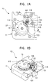
- the output gear 133 is meshed with the gear portion 155 of the cam gear 15 as shown in Figs. 7A and 7B, and the other mounting flange 131 is fastened to the screw bearing boss 120 with a screw 122 as shown Fig. 5.
- the present invention allows easy adjustment of the distance between the shafts of the output gear 133 and the gear portion 155, and in this meshing position, part of the output gear 133 gets into the inverted L-shaped fall-off prevention hook 121 as shown in Fig. 7B, therefore the output gear 133 does not come off the output shaft 132 thereafter.
- the see-through hole 153 is provided at the position at an angle of about 180 degrees relative to the portion without teeth 151, therefore after the cam gear 15 is attached in the cam gear housing recess 122, by rotating the cam gear 15 about 180 degrees, the see-through hole 153 appears in the cut-out portion 116, and this position is the initial position of the wind directing plate 4, that is, a totally closed position.
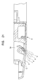
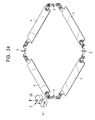
- a spring 16 for giving momentum in a direction to close two of wind directing plates 4c and 4d at the end adjacent to a fourth corner portion 3d is provided at the fourth corner portion 3d located on the diagonal line seen from the first corner portion 3a.
- each one of the springs 16 is attached to each of the joint members 53 and 53 of the wind directing plates 4c and 4d.
- the spring 16 has a coil portion 161 fitted onto the shaft portion of the joint member 53, a base end foot 162 drawn almost in a straight line from one end of the coil portion 161 so as to abut to the inner face of the front panel 3, and an engaging portion 163 which is drawn from the other end of the coil portion 161, and which is bent so as to engage in a hook portion 532 of the joint member 53.
- the spring 16 gives momentum to the wind directing plates 4c and 4d in a direction of an arrow B, that is, the direction of the totally closed position.
- the spring 17 has a coil portion 171 fitted onto the main shaft 51 of the hook type universal joint 5, a base end foot 172 which is drawn from one end of the coil portion 171, and which is bent so as to abut to the inner face of the front panel 3, and an engaging portion 173 which is drawn from the other end of the coil portion 171, and which is bent so as to engage in the lever 52 of the main shaft 51.
- the spring 17 gives momentum to the wind directing plates 4c and 4d in the direction of the totally closed position.
- an operational mode four modes, a cooling mode, a dehumidification mode, an air blowing mode, and a heating mode are prepared.
Landscapes
- Engineering & Computer Science (AREA)
- Chemical & Material Sciences (AREA)
- Combustion & Propulsion (AREA)
- Mechanical Engineering (AREA)
- General Engineering & Computer Science (AREA)
- Air-Flow Control Members (AREA)
- Air Filters, Heat-Exchange Apparatuses, And Housings Of Air-Conditioning Units (AREA)
- Devices For Blowing Cold Air, Devices For Blowing Warm Air, And Means For Preventing Water Condensation In Air Conditioning Units (AREA)
Applications Claiming Priority (2)
| Application Number | Priority Date | Filing Date | Title |
|---|---|---|---|
| JP10816298A JP3885846B2 (ja) | 1998-04-17 | 1998-04-17 | 空気調和機 |
| JP10816298 | 1998-04-17 |
Publications (3)
| Publication Number | Publication Date |
|---|---|
| EP0950867A2 true EP0950867A2 (de) | 1999-10-20 |
| EP0950867A3 EP0950867A3 (de) | 2001-05-23 |
| EP0950867B1 EP0950867B1 (de) | 2004-09-29 |
Family
ID=14477548
Family Applications (1)
| Application Number | Title | Priority Date | Filing Date |
|---|---|---|---|
| EP99301781A Expired - Lifetime EP0950867B1 (de) | 1998-04-17 | 1999-03-09 | Klimaanlage |
Country Status (13)
| Country | Link |
|---|---|
| US (1) | US6089972A (de) |
| EP (1) | EP0950867B1 (de) |
| JP (1) | JP3885846B2 (de) |
| KR (1) | KR19990082816A (de) |
| CN (1) | CN1134621C (de) |
| AR (1) | AR019044A1 (de) |
| AU (1) | AU764351C (de) |
| DE (1) | DE69920563T2 (de) |
| EG (1) | EG21399A (de) |
| ES (1) | ES2229628T3 (de) |
| ID (1) | ID22472A (de) |
| MY (1) | MY133896A (de) |
| TW (1) | TW374844B (de) |
Cited By (9)
| Publication number | Priority date | Publication date | Assignee | Title |
|---|---|---|---|---|
| WO2007123146A1 (ja) | 2006-04-21 | 2007-11-01 | Daikin Industries, Ltd. | 空気調和装置 |
| EP2023049A3 (de) * | 2007-07-25 | 2009-02-25 | Sanyo Electric Co., Ltd. | In die Decke eingebaute Klimaanlage und Innenraumeinheit dafür |
| CN103162350A (zh) * | 2011-12-12 | 2013-06-19 | 乐金电子(天津)电器有限公司 | 壁挂式空调室内机 |
| EP2918936A4 (de) * | 2012-10-30 | 2016-07-27 | Mitsubishi Electric Corp | Klimaanlage |
| EP3081876A3 (de) * | 2015-03-26 | 2017-01-11 | Fujitsu General Limited | Deckenintegrierte klimaanlage |
| CN109959142A (zh) * | 2017-12-22 | 2019-07-02 | 大金工业株式会社 | 出风面板和空调室内机 |
| EP3680571A4 (de) * | 2017-09-06 | 2021-06-09 | LG Electronics Inc. | Deckeninnenraumeinheit einer klimaanlage vom deckentyp |
| CN113137659A (zh) * | 2021-04-13 | 2021-07-20 | 珠海格力电器股份有限公司 | 室内机及具有其的空调器 |
| EP3686506A4 (de) * | 2017-09-20 | 2021-07-28 | LG Electronics Inc. | Decken-innenraumeinheit einer klimaanlage |
Families Citing this family (27)
| Publication number | Priority date | Publication date | Assignee | Title |
|---|---|---|---|---|
| JP3408983B2 (ja) * | 1999-01-25 | 2003-05-19 | 三菱電機株式会社 | 天井埋込型空気調和機 |
| US6802361B2 (en) * | 2000-06-22 | 2004-10-12 | Air Techno Company Limited | Ceiling panel structure for a ceiling-mounted air-conditioning apparatus or the like |
| US6569010B1 (en) * | 2002-04-25 | 2003-05-27 | Nuclimate Air Quality Systems, Inc. | Induced air distribution system |
| KR100606733B1 (ko) * | 2004-11-23 | 2006-08-02 | 엘지전자 주식회사 | 멀티공기조화기의 실내기 |
| JP4923639B2 (ja) * | 2005-11-11 | 2012-04-25 | ダイキン工業株式会社 | 空気調和装置の室内パネル及び空気調和装置 |
| JP5034473B2 (ja) * | 2006-12-12 | 2012-09-26 | ダイキン工業株式会社 | 空気調和装置の室内機 |
| KR101065830B1 (ko) * | 2008-12-29 | 2011-09-20 | 엘지전자 주식회사 | 천장형 공기조화기 |
| JP5473449B2 (ja) * | 2009-07-23 | 2014-04-16 | 三菱重工業株式会社 | 車両用空調装置 |
| JP5180167B2 (ja) * | 2009-09-04 | 2013-04-10 | 愛三工業株式会社 | 樹脂歯車及びスロットル装置 |
| CN102192581B (zh) * | 2010-03-03 | 2013-04-03 | 珠海格力电器股份有限公司 | 用于导风板组件的驱动装置及包括该驱动装置的空调机 |
| TWI398607B (zh) * | 2010-06-08 | 2013-06-11 | 廣東松下環境系統有限公司 | The fixed structure of the air duct switchboard of the heating ventilation fan |
| CN101858641B (zh) * | 2010-06-18 | 2012-05-30 | 广东志高空调有限公司 | 一种空调柜机出风结构 |
| JP5267690B2 (ja) * | 2012-02-03 | 2013-08-21 | ダイキン工業株式会社 | 室内機 |
| KR101706812B1 (ko) | 2013-10-02 | 2017-02-14 | 엘지전자 주식회사 | 카세트형 공기조화기의 실내기 |
| KR101702169B1 (ko) | 2013-10-02 | 2017-02-02 | 엘지전자 주식회사 | 카세트형 공기조화기의 실내기 |
| KR20150043573A (ko) | 2013-10-11 | 2015-04-23 | 엘지전자 주식회사 | 공기조화기의 실내기 |
| JP6072671B2 (ja) * | 2013-12-20 | 2017-02-01 | 三菱電機株式会社 | 室内機及び空気調和機 |
| KR101662377B1 (ko) * | 2014-01-27 | 2016-10-04 | 엘지전자 주식회사 | 공기조화기의 실내기 |
| GB2545350B (en) * | 2014-09-30 | 2020-06-17 | Mitsubishi Electric Corp | Dehumidification device |
| JP6439537B2 (ja) * | 2015-03-26 | 2018-12-19 | 株式会社富士通ゼネラル | 天井埋込型空気調和機 |
| JP6451445B2 (ja) * | 2015-03-26 | 2019-01-16 | 株式会社富士通ゼネラル | 天井埋込型空気調和機 |
| JP6701329B2 (ja) * | 2015-07-14 | 2020-05-27 | 広東美的制冷設備有限公司Gd Midea Air−Conditioning Equipment Co.,Ltd. | 駆動盤及び駆動機構 |
| CN104990245B (zh) * | 2015-07-14 | 2017-10-13 | 广东美的制冷设备有限公司 | 驱动机构 |
| CN106196318A (zh) * | 2016-07-15 | 2016-12-07 | 徐州工程学院 | 一种多层柜式空气净化仪及其工作方法 |
| CN108507109A (zh) * | 2018-05-10 | 2018-09-07 | 北京亚都新风净化工程技术有限公司 | 一种面板连接结构及新风机 |
| JP6687917B2 (ja) * | 2018-05-31 | 2020-04-28 | 株式会社富士通ゼネラル | 天井埋込型空気調和機 |
| CN115264586B (zh) * | 2022-07-11 | 2024-06-04 | 珠海格力电器股份有限公司 | 一种空调器壳体组件及空调内机 |
Family Cites Families (7)
| Publication number | Priority date | Publication date | Assignee | Title |
|---|---|---|---|---|
| JPH0652134B2 (ja) * | 1988-01-11 | 1994-07-06 | ダイキン工業株式会社 | 空気調和装置の風向変更装置 |
| JPH0823434B2 (ja) * | 1989-05-10 | 1996-03-06 | ダイキン工業株式会社 | 空気調和機 |
| JPH046343A (ja) * | 1990-04-25 | 1992-01-10 | Hitachi Ltd | 空気調和機 |
| JP3015562B2 (ja) * | 1991-11-11 | 2000-03-06 | 三洋電機株式会社 | 風向変更装置 |
| JPH06341702A (ja) * | 1993-06-02 | 1994-12-13 | Hitachi Ltd | 空気調和機 |
| TW384374B (en) * | 1996-10-03 | 2000-03-11 | Toshiba Corp | Indoor unit of air-conditioner |
| JP3719472B2 (ja) * | 1997-09-19 | 2005-11-24 | 株式会社富士通ゼネラル | 天埋型空気調和機 |
-
1998
- 1998-04-17 JP JP10816298A patent/JP3885846B2/ja not_active Expired - Fee Related
-
1999
- 1999-02-23 US US09/255,740 patent/US6089972A/en not_active Expired - Fee Related
- 1999-02-26 TW TW088102996A patent/TW374844B/zh active
- 1999-02-26 AU AU18481/99A patent/AU764351C/en not_active Ceased
- 1999-03-02 MY MYPI99000746A patent/MY133896A/en unknown
- 1999-03-09 DE DE69920563T patent/DE69920563T2/de not_active Expired - Fee Related
- 1999-03-09 EP EP99301781A patent/EP0950867B1/de not_active Expired - Lifetime
- 1999-03-09 ES ES99301781T patent/ES2229628T3/es not_active Expired - Lifetime
- 1999-03-31 KR KR1019990011306A patent/KR19990082816A/ko not_active Abandoned
- 1999-04-01 ID IDP990297A patent/ID22472A/id unknown
- 1999-04-09 AR ARP990101659A patent/AR019044A1/es active IP Right Grant
- 1999-04-16 CN CNB991048938A patent/CN1134621C/zh not_active Expired - Fee Related
- 1999-04-18 EG EG40899A patent/EG21399A/xx active
Cited By (20)
| Publication number | Priority date | Publication date | Assignee | Title |
|---|---|---|---|---|
| EP2017542A4 (de) * | 2006-04-21 | 2011-12-07 | Daikin Ind Ltd | Klimaanlage |
| US8511108B2 (en) | 2006-04-21 | 2013-08-20 | Daikin Industries, Ltd. | Air conditioning unit |
| WO2007123146A1 (ja) | 2006-04-21 | 2007-11-01 | Daikin Industries, Ltd. | 空気調和装置 |
| EP2023049A3 (de) * | 2007-07-25 | 2009-02-25 | Sanyo Electric Co., Ltd. | In die Decke eingebaute Klimaanlage und Innenraumeinheit dafür |
| US9255716B2 (en) | 2007-07-25 | 2016-02-09 | Panasonic Intellectual Property Management Co., Ltd. | In-ceiling mount type air conditioner and indoor unit thereof |
| CN103162350B (zh) * | 2011-12-12 | 2017-03-29 | 乐金电子(天津)电器有限公司 | 壁挂式空调室内机 |
| CN103162350A (zh) * | 2011-12-12 | 2013-06-19 | 乐金电子(天津)电器有限公司 | 壁挂式空调室内机 |
| US9995504B2 (en) | 2012-10-30 | 2018-06-12 | Mitsubishi Electric Corporation | Air conditioner having air outlet louver with varying curvature |
| EP2918936A4 (de) * | 2012-10-30 | 2016-07-27 | Mitsubishi Electric Corp | Klimaanlage |
| EP3081876A3 (de) * | 2015-03-26 | 2017-01-11 | Fujitsu General Limited | Deckenintegrierte klimaanlage |
| EP3270074A1 (de) * | 2015-03-26 | 2018-01-17 | Fujitsu General Limited | In raumdecke eingebettete klimaanlage |
| AU2016201838B2 (en) * | 2015-03-26 | 2021-05-20 | Fujitsu General Limited | Ceiling-Embedded Air Conditioner |
| EP3680571A4 (de) * | 2017-09-06 | 2021-06-09 | LG Electronics Inc. | Deckeninnenraumeinheit einer klimaanlage vom deckentyp |
| EP3686506A4 (de) * | 2017-09-20 | 2021-07-28 | LG Electronics Inc. | Decken-innenraumeinheit einer klimaanlage |
| EP4339526A3 (de) * | 2017-09-20 | 2024-05-22 | LG Electronics Inc. | Deckenmontierte innenraumeinheit für klimaanlage |
| EP4321818A3 (de) * | 2017-09-20 | 2024-08-14 | LG Electronics Inc. | Deckenmontierte innenraumeinheit für klimaanlage |
| CN109959142A (zh) * | 2017-12-22 | 2019-07-02 | 大金工业株式会社 | 出风面板和空调室内机 |
| EP3730860A4 (de) * | 2017-12-22 | 2021-02-10 | Daikin Industries, Ltd. | Ausblaspaneel und innenraumklimatisierungseinheit |
| CN109959142B (zh) * | 2017-12-22 | 2021-12-28 | 大金工业株式会社 | 出风面板和空调室内机 |
| CN113137659A (zh) * | 2021-04-13 | 2021-07-20 | 珠海格力电器股份有限公司 | 室内机及具有其的空调器 |
Also Published As
| Publication number | Publication date |
|---|---|
| JP3885846B2 (ja) | 2007-02-28 |
| US6089972A (en) | 2000-07-18 |
| JPH11304234A (ja) | 1999-11-05 |
| AU1848199A (en) | 1999-10-28 |
| CN1232947A (zh) | 1999-10-27 |
| KR19990082816A (ko) | 1999-11-25 |
| DE69920563D1 (de) | 2004-11-04 |
| ES2229628T3 (es) | 2005-04-16 |
| AR019044A1 (es) | 2001-12-26 |
| AU764351C (en) | 2004-03-25 |
| ID22472A (id) | 1999-10-21 |
| EG21399A (en) | 2001-10-31 |
| DE69920563T2 (de) | 2006-02-23 |
| TW374844B (en) | 1999-11-21 |
| MY133896A (en) | 2007-11-30 |
| CN1134621C (zh) | 2004-01-14 |
| EP0950867B1 (de) | 2004-09-29 |
| EP0950867A3 (de) | 2001-05-23 |
| AU764351B2 (en) | 2003-08-14 |
Similar Documents
| Publication | Publication Date | Title |
|---|---|---|
| US6089972A (en) | Air conditioner | |
| EP0943875B1 (de) | Klimaanlage | |
| EP1522795B1 (de) | Innenraumeinheit einer Klimaanlage | |
| US7275389B2 (en) | Indoor unit in air conditioner | |
| EP1526339B1 (de) | Innenraumeinheit einer Klimaanlage | |
| AU2004284343B2 (en) | Indoor unit in air conditioner | |
| US7181925B2 (en) | Indoor unit in air conditioner | |
| JPH0755246A (ja) | 風向調節装置 | |
| JP2001133032A (ja) | 天井埋込形空気調和機の風向変更装置 | |
| CN108286746B (zh) | 一种导风板组件和空调 | |
| EP1837607A2 (de) | Innenraumeinheit für eine Klimaanlage | |
| JP2002300431A (ja) | 設置機構を有するカメラ | |
| JPH10318597A (ja) | 空気調和機 | |
| JP2018189309A (ja) | 空気調和装置の室内機 | |
| ZA200603706B (en) | Indoor unit in air conditioner | |
| JP3021143B2 (ja) | 空気調和機の吸込グリル回転支持装置 | |
| JPH0320675Y2 (de) | ||
| JPH10227518A (ja) | 空気調和機の吹出口構造 | |
| JP2834215B2 (ja) | ダンパー装置 | |
| CN116066895A (zh) | 空调室内机和空调器 | |
| KR20000065559A (ko) | 에어컨디셔너의 실내기 고정장치 | |
| JP2000346436A (ja) | 浴室温風乾燥装置のルーバー翼閉止防止機構 |
Legal Events
| Date | Code | Title | Description |
|---|---|---|---|
| PUAI | Public reference made under article 153(3) epc to a published international application that has entered the european phase |
Free format text: ORIGINAL CODE: 0009012 |
|
| AK | Designated contracting states |
Kind code of ref document: A2 Designated state(s): DE ES FR GB GR IT PT |
|
| AX | Request for extension of the european patent |
Free format text: AL;LT;LV;MK;RO;SI |
|
| PUAL | Search report despatched |
Free format text: ORIGINAL CODE: 0009013 |
|
| AK | Designated contracting states |
Kind code of ref document: A3 Designated state(s): AT BE CH CY DE DK ES FI FR GB GR IE IT LI LU MC NL PT SE |
|
| AX | Request for extension of the european patent |
Free format text: AL;LT;LV;MK;RO;SI |
|
| 17P | Request for examination filed |
Effective date: 20011119 |
|
| AKX | Designation fees paid |
Free format text: DE ES FR GB GR IT PT |
|
| 17Q | First examination report despatched |
Effective date: 20030714 |
|
| GRAP | Despatch of communication of intention to grant a patent |
Free format text: ORIGINAL CODE: EPIDOSNIGR1 |
|
| GRAS | Grant fee paid |
Free format text: ORIGINAL CODE: EPIDOSNIGR3 |
|
| GRAA | (expected) grant |
Free format text: ORIGINAL CODE: 0009210 |
|
| AK | Designated contracting states |
Kind code of ref document: B1 Designated state(s): DE ES FR GB GR IT PT |
|
| REG | Reference to a national code |
Ref country code: GB Ref legal event code: FG4D |
|
| REF | Corresponds to: |
Ref document number: 69920563 Country of ref document: DE Date of ref document: 20041104 Kind code of ref document: P |
|
| REG | Reference to a national code |
Ref country code: GR Ref legal event code: EP Ref document number: 20040404204 Country of ref document: GR |
|
| PGFP | Annual fee paid to national office [announced via postgrant information from national office to epo] |
Ref country code: GR Payment date: 20050211 Year of fee payment: 7 |
|
| PGFP | Annual fee paid to national office [announced via postgrant information from national office to epo] |
Ref country code: DE Payment date: 20050304 Year of fee payment: 7 |
|
| PGFP | Annual fee paid to national office [announced via postgrant information from national office to epo] |
Ref country code: FR Payment date: 20050308 Year of fee payment: 7 |
|
| PGFP | Annual fee paid to national office [announced via postgrant information from national office to epo] |
Ref country code: GB Payment date: 20050309 Year of fee payment: 7 |
|
| REG | Reference to a national code |
Ref country code: ES Ref legal event code: FG2A Ref document number: 2229628 Country of ref document: ES Kind code of ref document: T3 |
|
| PGFP | Annual fee paid to national office [announced via postgrant information from national office to epo] |
Ref country code: ES Payment date: 20050425 Year of fee payment: 7 |
|
| ET | Fr: translation filed | ||
| PLBE | No opposition filed within time limit |
Free format text: ORIGINAL CODE: 0009261 |
|
| STAA | Information on the status of an ep patent application or granted ep patent |
Free format text: STATUS: NO OPPOSITION FILED WITHIN TIME LIMIT |
|
| 26N | No opposition filed |
Effective date: 20050630 |
|
| PG25 | Lapsed in a contracting state [announced via postgrant information from national office to epo] |
Ref country code: GB Free format text: LAPSE BECAUSE OF NON-PAYMENT OF DUE FEES Effective date: 20060309 |
|
| PG25 | Lapsed in a contracting state [announced via postgrant information from national office to epo] |
Ref country code: ES Free format text: LAPSE BECAUSE OF NON-PAYMENT OF DUE FEES Effective date: 20060310 |
|
| PGFP | Annual fee paid to national office [announced via postgrant information from national office to epo] |
Ref country code: IT Payment date: 20060331 Year of fee payment: 8 |
|
| PG25 | Lapsed in a contracting state [announced via postgrant information from national office to epo] |
Ref country code: DE Free format text: LAPSE BECAUSE OF NON-PAYMENT OF DUE FEES Effective date: 20061003 |
|
| GBPC | Gb: european patent ceased through non-payment of renewal fee |
Effective date: 20060309 |
|
| REG | Reference to a national code |
Ref country code: FR Ref legal event code: ST Effective date: 20061130 |
|
| REG | Reference to a national code |
Ref country code: ES Ref legal event code: FD2A Effective date: 20060310 |
|
| PG25 | Lapsed in a contracting state [announced via postgrant information from national office to epo] |
Ref country code: PT Free format text: LAPSE BECAUSE OF NON-PAYMENT OF DUE FEES Effective date: 20050228 |
|
| PG25 | Lapsed in a contracting state [announced via postgrant information from national office to epo] |
Ref country code: FR Free format text: LAPSE BECAUSE OF NON-PAYMENT OF DUE FEES Effective date: 20060331 |
|
| PG25 | Lapsed in a contracting state [announced via postgrant information from national office to epo] |
Ref country code: GR Free format text: LAPSE BECAUSE OF NON-PAYMENT OF DUE FEES Effective date: 20061002 |
|
| PG25 | Lapsed in a contracting state [announced via postgrant information from national office to epo] |
Ref country code: IT Free format text: LAPSE BECAUSE OF NON-PAYMENT OF DUE FEES Effective date: 20070309 |