EP0951983A2 - Système et procédé de fixation pour élément de moule - Google Patents
Système et procédé de fixation pour élément de moule Download PDFInfo
- Publication number
- EP0951983A2 EP0951983A2 EP99850069A EP99850069A EP0951983A2 EP 0951983 A2 EP0951983 A2 EP 0951983A2 EP 99850069 A EP99850069 A EP 99850069A EP 99850069 A EP99850069 A EP 99850069A EP 0951983 A2 EP0951983 A2 EP 0951983A2
- Authority
- EP
- European Patent Office
- Prior art keywords
- mold
- jaw
- piston
- mold element
- spigot
- Prior art date
- Legal status (The legal status is an assumption and is not a legal conclusion. Google has not performed a legal analysis and makes no representation as to the accuracy of the status listed.)
- Withdrawn
Links
Images




Classifications
-
- B—PERFORMING OPERATIONS; TRANSPORTING
- B29—WORKING OF PLASTICS; WORKING OF SUBSTANCES IN A PLASTIC STATE IN GENERAL
- B29C—SHAPING OR JOINING OF PLASTICS; SHAPING OF MATERIAL IN A PLASTIC STATE, NOT OTHERWISE PROVIDED FOR; AFTER-TREATMENT OF THE SHAPED PRODUCTS, e.g. REPAIRING
- B29C45/00—Injection moulding, i.e. forcing the required volume of moulding material through a nozzle into a closed mould; Apparatus therefor
- B29C45/17—Component parts, details or accessories; Auxiliary operations
- B29C45/26—Moulds
- B29C45/263—Moulds with mould wall parts provided with fine grooves or impressions, e.g. for record discs
- B29C45/2632—Stampers; Mountings thereof
-
- B—PERFORMING OPERATIONS; TRANSPORTING
- B29—WORKING OF PLASTICS; WORKING OF SUBSTANCES IN A PLASTIC STATE IN GENERAL
- B29C—SHAPING OR JOINING OF PLASTICS; SHAPING OF MATERIAL IN A PLASTIC STATE, NOT OTHERWISE PROVIDED FOR; AFTER-TREATMENT OF THE SHAPED PRODUCTS, e.g. REPAIRING
- B29C45/00—Injection moulding, i.e. forcing the required volume of moulding material through a nozzle into a closed mould; Apparatus therefor
- B29C45/17—Component parts, details or accessories; Auxiliary operations
- B29C45/1742—Mounting of moulds; Mould supports
- B29C45/1743—Mounting of moulds; Mould supports using mounting means projecting from the back side of the mould or from the front side of the mould support
-
- Y—GENERAL TAGGING OF NEW TECHNOLOGICAL DEVELOPMENTS; GENERAL TAGGING OF CROSS-SECTIONAL TECHNOLOGIES SPANNING OVER SEVERAL SECTIONS OF THE IPC; TECHNICAL SUBJECTS COVERED BY FORMER USPC CROSS-REFERENCE ART COLLECTIONS [XRACs] AND DIGESTS
- Y10—TECHNICAL SUBJECTS COVERED BY FORMER USPC
- Y10S—TECHNICAL SUBJECTS COVERED BY FORMER USPC CROSS-REFERENCE ART COLLECTIONS [XRACs] AND DIGESTS
- Y10S425/00—Plastic article or earthenware shaping or treating: apparatus
- Y10S425/81—Sound record
Definitions
- the present invention relates to a method and system for retaining a replaceable mold element in place on a molding machine. More specifically, the present invention relates to a retaining and releasing mechanism and actuation system located in a mold half which can engage spigots of various sizes and designs that are attached to a mold element. Preferred embodiments are disclosed in detail wherein a CD or DVD stamper plate or a CD or DVD mold half are retained in an accurate and secure operative position on a molding machine. This method and system allows exchange of a mold element for another in a novel and effective manner.
- mold elements such as mold inserts, the mold cavity and/or the mold core plates have been retained in place on the mold machine via manually activated retaining and releasing means such as bolts, etc. While such means provide good mechanical strength and can be inexpensive to employ, mold elements retained by them are generally not easily or quickly removed from the mold machine.
- the mold element that has to be changed rapidly can be the entire mold, or just one mold half.
- the mold half is thus removable connected to an injection molding machine platen.
- Guyon requires a lot of space due to the fact that the cylinder is in a transverse position in order to move the wedge laterally with respect to the peg.
- the working surfaces of the wedge and of the peg can be worn out due to the high friction they are exposed to in use.
- Information carrier articles such as CDs (compact discs) or DVDs (digital versatile discs) are typically molded in a three part mold, comprising a stationary mold plate, a movable mold plate and a stamper plate.
- the stamper plate is a removable mold element which is maintained in the mold cavity formed between the stationary and the movable mold plates.
- the stamper is a plate-like disc element with upstanding bosses responsible for forming the encoded digital information carrier pits in the molded final article. Each time a different information title is to be molded, the stamper is changed appropriately.
- the technical and patent literature disclose several ways to retain the stamper plate in a CD mold.
- the first way is to hold directly the stamper plate using vacuum or magnetic clamping means as shown for example in the US Patent 5,552,098 to Kudo and more recently in the US Patent 5,612,062 to Takahashi.
- the second way is to use a central holder attached to the stamper plate that is retained using either mechanical means or vacuum means.
- US Patent 5,116,210 of Watanabe et al. shows the mechanical approach and US Patent 5,297,951 of Asai shows the vacuum approach.
- a third way is to use a combination of the direct and the central holding means.
- the direct means can be a ring pressing the outer diameter of the stamper plate which is employed with a central holding means. This combined approach is disclosed amongst other in the US Patent 4,917,833 of Cools and Patent 5,297,951 of Asai.
- Cools shows a spring based stamper releasing mechanism comprising in the mold half a movable thrust plate connected to a ball bushing.
- This ball bushing further comprises several circumferential bores wherein balls are located to engage changer sleeve through the annular groove adapted to catch the balls.
- An outer bushing also has groove adapted to release the balls when they come in alignment.
- stamper plate can be replaced due to the ejection force upon the sleeve.
- This design is not suitable for most CD applications as it requires a mechanical guard ring to hold the exterior of the stamper and to further activate the spring based retaining/releasing elements.
- Figure 4 of this reference shows a similar prior art system wherein the centre bush includes a locking ring distal the stamper, instead of the threaded portion.
- a pair of horizontal control rods extend through the mold plate and into each side of the bore into which the bush is received.
- the portions of the control in the bore include cam surfaces which engage the locking ring of the bush to urge the stamper into engagement with the mold plate when the control rods are rotated.
- Figures 1 and 2 of this reference show a system wherein the centre bush includes a threaded portion, similar to the embodiment shown in Figure 3, which is engaged by a pair of control rods, similar to those of Figure 4, but which include toothed portions to engage the threaded portion, rather than cam surfaces.
- the mechanisms shown in the Takahashi reference also suffer from disadvantages. Specifically, as stated by Takahashi, the face-gear mechanism of the embodiment of Figure 3 occupies a significant volume within the mold plate, thus interfering with the routing and sizing of mold cooling systems within the mold plate. Also, the embodiment of Figure 4 suffers from the disadvantage that the extent to which the stamper may be lifted above the mold plate is limited by the diameter of the control rods and their cam surfaces. Also, the embodiment of Figures 1 and 2 is somewhat delicate, requiring proper engagement of the threaded portion of the centre bush with the toothed control rods. Finally, each of these embodiments is intended to be operated by a human operator who is responsible for changing the stamper and do not lend themselves well to use with automated and/or robotic systems for changing the stampers.
- U.S. Patent 5,401,158 to Kubota et al. shows a different concept to exchange a first stamper unit with another.
- each stamper is mounted to a stamper carrier, which is in fact the movable mold half, in a conventional manner to form a stamper assembly.
- the apparatus removes one stamper assembly and replaces it with another to effect a change of the stamper.
- this apparatus requires that each stamper be mounted to its own stamper carrier mold, this results in the stamper assemblies having much more mass than the stamper alone. To bring this increased mass up to mold operating temperature requires a significant time in which the mold can not be operated, necessitating that the apparatus preheat the stamper assembly before exchanging it for a stamper assembly already within the mold. Further, the requirement for a stamper carrier for each stamper increases the overall costs to mold the articles.
- the present invention provides a system and method of releasably retaining a mold element, such as a stamper plate, within a mold or an injection molding machine platen.
- the system is located inside a single mold half with little or no space penalty and employs slidable retaining and actuation mechanisms.
- the present invention can be applied regardless of whether other retaining means of the stamper plate, such as retaining rings, magnets or vacuum pipes are employed in the mold.
- the present invention allows changing of a stamper plate or the like very rapidly and without any operator assistance or intervention if it is used in correlation with a suitable robotics arm or other mechanical automated handling means.
- the present invention is also believed to be particularly useful for CD and DVD injection molding machines which are employed molding very short-run titles and which thus require tens of changes of stamper plates per day.
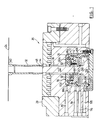
- a mold element retaining and releasing apparatus in accordance with a first embodiment of the present invention is indicated generally at 20 in Figures 1 and 2.
- Apparatus 20 can be employed with an injection mold used to manufacture information carriers such as CDs and DVDs and operable in conjunction with an injection molding machine, such as described in the copending US Patent application no 736,513 assigned to the assignee of the present invention.
- Retaining apparatus 20 is operable to receive, engage, maintain and release a mold element, such as a known stamper plate 24, in position relative to another mold element, such as movable mold half plate 28.
- a known locating and retaining means such as spigot 32, is attached to stamper plate 24 and is received in a bore 36 in mold half plate 28.
- spigot 32 is circular in cross-section and bore 36 is of a complementary, generally cylindrical, shape and has a diameter that is closely toleranced to the diameter of spigot 32 to substantially eliminate free play between spigot 32 and bore 36 to ensure that stamper 24 is tightly maintained in position relative to mold plate 28 during the injection process and during the ejection of a molded disc.
- the portion 40 of spigot 32 that is adjacent stamper 24 can be tapered at the bottom portion, from a larger diameter adjacent stamper 24 to a reduced diameter distal stamper 24 and bore 36 can include a complementary tapered portion 44 to receive portion 40 and to thereby further register the position of stamper 24 relative to mold plate 28.
- spigot 32 and bore 36 are shown as being circular in cross section in this Figure, it will be apparent to those of skill in the art that the present invention is not so limited and spigot 32 and bore 36 can include an index means, such as an upraised key on spigot 32 and a complementary groove on bore 36, to provide for angular registration of stamper 24 with respect to mold half plate 28. Similarly, spigot 32 and bore 36 can be square, rectangular or other suitable cross-sectional shapes as desired.
- spigot 32 includes a retaining portion, such as for example groove 48, distal stamper 24.
- a retaining portion such as for example groove 48
- distal stamper 24 When spigot 32 is inserted into bore 36, as shown in Figure 2, and stamper 24 is in position against mold plate 28, groove 48 is adjacent to a retainer means which can engage groove 48 to retain stamper 24 in place.
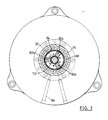
- the retainer means in this embodiment of the present invention comprises a chuck 56, best seen in Figure 3, which uses slidable jaw means 60 to engage groove 48 to prevent spigot 32, and therefore stamper 24, from being moved relative to mold plate 28 and thus secure the stamper into the mold cavity during all the steps of the injection process.
- chuck 56 includes three radially slidable jaws 60a, 60b and 60c which are located at equi-spaced positions about the diameter of bore 36.
- a biasing means such as o-ring spring 64, urges each jaw 60 into bore 36 such that jaws 60 can engage groove 48.
- chuck 56 is located and attached to the inner part of an actuator, such as for example piston 68.
- Piston 68 has inner diameter 69 and is slideably movable with respect to the longitudinal axis of bore 36.
- piston 68 includes a pneumatic seal, such as o-ring 72, which sealingly engages the inner lateral surface 75 of a multifunctional and removable piston housing 76.
- a fluid under pressure such as air (which for CDs and DVDs molding is preferable as being cleaner than oil) or oil, can be introduced into piston housing 76 above o-ring 72, via a conduit 80, to bias piston 68 away from mold plate 28, thus moving jaws 60 radially inward, as described below.
- air, or another pressurized fluid can be introduced into piston housing 76 below o-ring 72, via a conduit 84, to bias piston 68 toward mold plate 28, thus moving jaws 60 radially outward, as described below.
- each jaw 60 includes an upper inclined retaining and guiding surface 88 which abuts a complementary inclined surface comprising cam 92.
- Cam 92 is part of the inner base surface 77 of piston housing 76 such that, when piston 68 is biased towards mold plate 28, inclined surface 88 on each jaw 60 rides up on cam 92 on housing 76.
- a suitable spring means such as for example o-ring spring 64 is used to maintain permanent contact between the cams and the jaws and thus each jaw 60 retracts (moves radially outward) from bore 36 as shown in Figure 1.
- inclined surface 88 on each jaw 60 jaw rides down on cam surface 92 and thus each jaw 60 advances (moves radially inward) into bore 36 to engage groove 48, and thus retain stamper plate 24.
- chuck 56 include three equi-spaced jaws 60
- a single jaw can be employed in some contemplated circumstances. In other contemplated circumstances, such as when the retained mold element is subject to relatively large mechanical forces during molding operations, more than three jaws 60 can be employed for additional mechanical strength.
- biasing means other than o-ring 64 such as coil springs, can be employed to urge jaws 60 into bore 36 when increased bias forces are desirable.
- a workpiece ejection mechanism to facilitate removal of the molded article from within the mold.
- plastic information carriers such as CDs and/or DVDs
- an ejection mechanism to facilitate the separation of the molded CD or DVD from the cavity mold comprising the stamper plate at the completion of the molding operation.
- a mechanical workpiece ejection mechanism located in the mold plate is provided in the form of workpiece ejector 100.
- Workpiece ejector 100 includes a piston 104 which rides within a lower housing 106 and which includes a sealing means, such as o-ring 108, which sealingly engages the inner surface of housing 76.
- Workpiece ejector 100 also includes an ejector rod 112 which extends toward stamper 24 from piston 104 through bore 36.
- Ejector rod 112 has a cross-sectional shape which is complementary to the interior cross-section of spigot 32 such that spigot 32 can be inserted between the inner wall of bore 36 and the outer surface of ejector rod 112 as shown in Figure 2.
- piston 104 can be urged toward or away from stamper 24 via pneumatic pressure.
- a suitable pneumatic fluid such as air
- a suitable pneumatic fluid such as air
- a suitable pneumatic fluid such as air can be introduced into lower housing 106, below piston 104, through a conduit 120 to urge piston 104 toward stamper 24.
- a seal such as o-ring 124, isolates pneumatic fluid beneath piston 68 in housing 76 from pneumatic fluid above piston 104 in lower housing 106.
- pneumatic fluid is supplied through conduit 120 at the end of the mold cycle and piston 104 is urged toward stamper 24, raising ejector rod 112. Raised ejector rod 112 abuts the molded article formed on stamper 24 and separates the molded article therefrom allowing the article to be extracted from the mold. Pneumatic fluid is then supplied through conduit 116 to retract ejector rod 112 for the start of the next mold cycle.
- spigot 32 of the stamper 24 which is to be retained is inserted into bore 36 until groove 48 is located adjacent chuck 56.
- Pneumatic fluid is supplied through conduit 80 urging piston 68 away from stamper 24 and allowing inclined surfaces 88 of jaws 60 to ride down cams 92 of housing 76 and jaws 60 to extend into bore 36 and groove 48, thus retaining spigot 32 and stamper 24 in place in the mold.
- the supply of pneumatic fluid through conduit 80 is maintained whenever a stamper is in place as this maintains pressure on piston 68 and results in spigot 32 being exposed to a tensioning force which assists in keeping the stamper in position.
- a conventional robotic arm 140 can be employed to load and unload stampers.
- Robotic arm 140 can engage a stamper 24 with a vacuum means, or other suitable means as will occur to those of skill in the art and, to load stamper 24, robotic arm 140 need only align spigot 32 with bore 36 and insert spigot 32 therein.
- robotic arm 140 need only engage stamper 24 and withdraw spigot 32 from bore 36.
- pneumatic fluid will be supplied appropriately to engage and/or disengage jaws 60 as appropriate.
- a second embodiment of the present invention is indicated generally at 200 in Figure 4 where a novel spigot means employs a different retention mechanism that is actuated in a manner similar to the one shown in Figs. 1-2.
- the spigot is an elongated tube which is quite heavy and has a length which requires opening of the mold during the stamper plate change operation much more than is normally needed to only eject the molded disc after each injection cycle.
- storing a stamper plate with a conventional spigot in a stamper replacement magazine close to the injection molding machine becomes more problematic due to the length of the spigot.
- the robotics arm needed to handle the stamper plate and the spigot has to be also very robust and thus heavier and slower than the robotics arm used to handle the ejected only CDs and DVDs.
- a mold element to be retained such as stamper plate 204
- a novel spigot means 208 is generally shorter, lighter and easier to manufacture and attach to the stamper plate then conventional spigots.
- Spigot means 208 includes a neck portion 212 which is adjacent stamper 204, a body portion 211 and a lower tip portion 213. Lower tip portion 213 can extend sufficiently to allow the retention mechanism to engage spigot means 208 before it goes into the mold plate, spigot means 208 being further moved for only a very short distance to be secured to the mold.
- a half mold plate 216 includes within it a piston housing 220 in which a slidable piston 224 is located.
- Piston 224 includes a sealing member, such as o-ring 228, which separates the interior of piston housing 220 into a pneumatic chamber above piston 224 and a pneumatic chamber below piston 224.
- Piston 224 further includes an upstanding cylindrical connecting member 232 that engages a collet means 236 that is used to engage and disengage spigot means 208.
- Collet means 236 comprises at least two split elongated-parts or jaws that are used to engage spigot means 208 when they are forced against each other.
- three elongate jaws 240a, 240b and 240c (not shown) which have spring-like characteristics and are joined at bottom portion 235 adjacent to the point at which collet means 236 connects to actuating member 232.
- Each jaw 240 include a profiled portion comprising a collar 248 which is substantially complementary in shape to neck portion 212 on spigot 208.
- Each jaw 240 further includes outer sides which are tapered from a maximum exterior dimension adjacent collar 248 to a minimum exterior dimension distal collar 248.
- a fluid conduit allows any suitable pneumatic fluid, such as air, to be introduced below piston 224 in housing 220 urging piston 224 upward, toward bore 244, thus moving actuating member 232 and collet means 236 within bore 244 toward the cavity mold portion 201 and stamper plate 204.
- any suitable pneumatic fluid such as air
- a suitable pneumatic fluid such as air
- a fluid conduit (not shown) above piston 224 in piston housing 220, urging piston 224 downward, away from bore 244, thus moving actuating member 232 within bore 244 away from the cavity mold surface 201 together with the stamper plate 204.
- a suitable pneumatic fluid such as air
- the supply of pneumatic fluid to piston 224 to urge it downward, away from bore 244 is maintained whenever a stamper is in place. In this manner, spigot 212 is exposed to a tensioning force which assists in maintaining it in position.
- spigot 208 can be relatively short, as is the stroke required to extend and retract collet means 236, thus avoiding the necessity of opening the mold to a larger extent. Further, the mass of collet means 236, actuator 232 and piston 224 is relatively small and, in combination with the short stroke, allows relatively quick cycling operation of the mold element retaining apparatus.
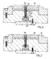
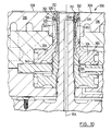
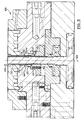
- FIG. 3 Another embodiment of the present invention is indicated generally at 300 in Figures 9 and 10.
- apparatus 300 is shown in the loading (up) position on the left side of line 304 and in the loaded (down) position on the right side of line 304.
- a stamper 308 has a spigot 312 attached which is much shorter than those of the embodiments described above.
- Spigot 312 includes a retaining means, in this example groove 316, which is engaged by jaws 320.
- three jaws 320 are provided, each jaw 320 being an elongate member which extends upwardly from a piston 324.
- piston 324 is annular and encircles a central bore 325.
- Each jaw 320 includes a cam surface 328 at its uppermost end which rides on an inclined surface 332 of mold plate 336 and further includes a tooth 326 to engage groove 316.
- the dimensions and material of jaws 320 are selected to provide a degree of spring-like resilience to jaws 320 and thus jaws 320 are biased radially inwardly with respect to central bore 325.
- piston 324 When a supply of a pneumatic fluid, such as air, is provided to the volume 340 below piston 324, piston 324 is moved upwardly, moving jaws 320 upwardly also. As each jaw 320 moves upwardly, its cam surface 328 rides on its respective inclined surface 332 which urges the upper portion of jaw 320 away from spigot 312 and disengages tooth 326 from groove 316 (if a stamper is present) as shown on the left side of line 304. In this position, a stamper can be removed and/or loaded into apparatus 300.
- a pneumatic fluid such as air
- this embodiment is believed to provide advantages in that the length of spigot 312 is much less than conventional spigots, thus reducing the degree to which the mold must be opened to remove or load a stamper, compared to conventional spigots.
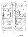
- apparatus 400 is shown in the loading (up) position on the left side of line 404 and in the loaded (down) position on the right side of line 404.
- Spigot 408 (which is shown unattached to a stamper) includes an elongate body 412 and a retaining means, in this example groove 416.
- a set of pivoting jaws 420 are provided to engage groove 416.
- three equi-spaced jaws 420 are provided.
- Each jaw 420 is mounted by a pivot pin 424 to a piston 428 and each jaw 420 includes a retainer engagement end 432 and a mold plate abutment end 436.
- piston 428 is annular and encircles a central bore 440.
- Each jaw 420 includes a cam surface 444 adjacent the retainer engagement end 432 and the mold plate 448 includes an inclined surface 452 on which cam surface 444 rides.
- a biasing means, such as a helical spring 452 is also provided to bias jaws 420 to the position of the jaw 420 shown on the right hand side of line 404.
- the supply of pneumatic fluid to volume 456 is maintained when a stamper is in place so that jaws 420 are subject to a tensioning force which acts on the stamper through spigot 408 and which assists in maintaining the stamper in place.
Landscapes
- Engineering & Computer Science (AREA)
- Manufacturing & Machinery (AREA)
- Mechanical Engineering (AREA)
- Moulds For Moulding Plastics Or The Like (AREA)
- Injection Moulding Of Plastics Or The Like (AREA)
Applications Claiming Priority (2)
| Application Number | Priority Date | Filing Date | Title |
|---|---|---|---|
| US8286698P | 1998-04-24 | 1998-04-24 | |
| US82866P | 1998-04-24 |
Publications (2)
| Publication Number | Publication Date |
|---|---|
| EP0951983A2 true EP0951983A2 (fr) | 1999-10-27 |
| EP0951983A3 EP0951983A3 (fr) | 2001-08-29 |
Family
ID=22173940
Family Applications (1)
| Application Number | Title | Priority Date | Filing Date |
|---|---|---|---|
| EP99850069A Withdrawn EP0951983A3 (fr) | 1998-04-24 | 1999-04-22 | Système et procédé de fixation pour élément de moule |
Country Status (4)
| Country | Link |
|---|---|
| US (1) | US6325614B1 (fr) |
| EP (1) | EP0951983A3 (fr) |
| JP (1) | JP2000061985A (fr) |
| TW (1) | TW430602B (fr) |
Cited By (1)
| Publication number | Priority date | Publication date | Assignee | Title |
|---|---|---|---|---|
| CN108582671A (zh) * | 2018-04-26 | 2018-09-28 | 湖州新元素金属制品有限公司 | 一种便于更换的注塑制品用模具 |
Families Citing this family (6)
| Publication number | Priority date | Publication date | Assignee | Title |
|---|---|---|---|---|
| US6558145B2 (en) * | 2000-07-06 | 2003-05-06 | Klaus A. Wieder | Mold interlock |
| EP1731287A4 (fr) * | 2004-03-31 | 2009-11-11 | Sumitomo Heavy Industries | Poinçon de moulage de disque, plaque à surface miroir et objet moulé |
| US20090061043A1 (en) * | 2007-08-27 | 2009-03-05 | Husky Injection Molding Systems Ltd. | Mold Insert Fixture Mechanism |
| TWI451961B (zh) * | 2009-06-11 | 2014-09-11 | Hon Hai Prec Ind Co Ltd | 模具結構 |
| CN106273291A (zh) * | 2015-05-20 | 2017-01-04 | 鸿富锦精密工业(深圳)有限公司 | 开闭器装置及具有该开闭器装置的模具 |
| CN119238861B (zh) * | 2024-12-04 | 2025-04-25 | 成都宝利根创科电子有限公司 | 一种模内切除料柄的注塑模具及注塑生产方法 |
Family Cites Families (34)
| Publication number | Priority date | Publication date | Assignee | Title |
|---|---|---|---|---|
| CH612862A5 (fr) * | 1976-06-29 | 1979-08-31 | Netstal Ag Maschf Giesserei | |
| DE2938665C2 (de) * | 1979-09-25 | 1984-05-17 | Krauss-Maffei AG, 8000 München | Aufspannvorrichtung zum Aufspannen von Formteilen einer Spritzgießform auf Formaufspannplatten einer Formschließvorrichtung |
| US4372738A (en) * | 1981-10-27 | 1983-02-08 | Pemco-Kalamazoo, Inc. | Collet lock for a mold assembly |
| JPS58222827A (ja) * | 1982-06-22 | 1983-12-24 | Sumitomo Heavy Ind Ltd | 射出成形用金型の自動交換装置 |
| DE3435856A1 (de) * | 1983-10-05 | 1985-04-25 | H. Muller, Fabriques de Moules, Pont-de-la-Morge, Sion | Werkzeugeinrichtung fuer eine kunststoff-spritzgiessmaschine zum herstellen von informationstraegerscheiben mittels matrize |
| CH663929A5 (en) * | 1983-10-07 | 1988-01-29 | Mueller H Fab De Moules | Injection moulding machine matrix disc changing attachment - with expansion shell actuated by hydraulic power cylinder |
| FR2570640B1 (fr) * | 1984-09-26 | 1987-03-20 | Vallet Marc | Attelage d'ejection pour presse a injecter |
| DE3436182C1 (de) | 1984-10-03 | 1985-11-14 | Karl 7298 Loßburg Hehl | Spritzgiessform fuer Kunststoff-Spritzgiessmaschine mit Verriegelungseinrichtung |
| US4561626A (en) | 1984-10-25 | 1985-12-31 | Pemco-Kalamazoo, Inc. | Mold opening device |
| DE3446687A1 (de) | 1984-12-21 | 1986-07-03 | Günter Horst 7927 Sontheim Röhm | Kraftbetaetigtes backenspannfutter fuer exzentrisch zu spannende werkstuecke |
| DE3622453A1 (de) * | 1986-07-04 | 1988-01-07 | Roehm Guenter H | Dreibacken-spannfutter fuer drehmaschinen |
| US4755981A (en) | 1987-01-27 | 1988-07-05 | Ekhoff Donald L | Spindle clamp for removable disks |
| FR2612835B1 (fr) * | 1987-03-26 | 1989-05-26 | Coutier Andre | Dispositif de bridage pour la fixation amovible des moules de conformation sur les plateaux des presses de moulage |
| KR900007341B1 (ko) | 1987-04-16 | 1990-10-08 | 가부시기가이샤 싱고 세루 빅구 | 수지 성형용 카세트형 금형 |
| JP2824486B2 (ja) | 1987-12-24 | 1998-11-11 | ティーディーケイ 株式会社 | 光ディスク等用成型装置 |
| US5316466A (en) | 1987-12-24 | 1994-05-31 | Tdk Corporation | Disc molding apparatus |
| US5112205A (en) | 1989-05-15 | 1992-05-12 | Sony Corporation | Optical-disk manufacturing apparatus |
| US5056082A (en) * | 1989-06-12 | 1991-10-08 | Ekhoff Donald L | Apparatus for clamping removable disks |
| DE3929717A1 (de) | 1989-09-07 | 1991-03-14 | Battenfeld Gmbh | Befestigungsvorrichtung fuer werkzeuge an einem werkzeugtraeger |
| US5044921A (en) * | 1990-02-05 | 1991-09-03 | Joseph Micelli | Releasable mold locking apparatus |
| DE4042499C2 (de) | 1990-12-21 | 1995-05-04 | Marianne Wieser | Gießform zum Herstellen von Formwerkstücken |
| JP2882702B2 (ja) * | 1991-05-20 | 1999-04-12 | 株式会社神戸製鋼所 | タイヤ加硫機の金型クランプ装置 |
| JP2577290B2 (ja) | 1992-03-18 | 1997-01-29 | 日精樹脂工業株式会社 | スタンパユニットの交換方法及び自動交換装置 |
| DE4213655C2 (de) | 1992-04-25 | 1994-08-18 | Karl Hehl | Formschließeinheit für eine Kunststoff-Spritzgießmaschine |
| US5297951A (en) | 1992-05-13 | 1994-03-29 | Kabushiki Kaisha Meiki Seisakusho | Mold for producing molded discs |
| US5456588A (en) | 1992-06-15 | 1995-10-10 | Olympus Optical Co. Ltd. | Injection mold device |
| AU6220994A (en) | 1993-02-22 | 1994-09-14 | Ict Axxicon B.V. | Changing device for manufacturiing information carriers by injection moulding |
| JP2974230B2 (ja) | 1993-04-23 | 1999-11-10 | 株式会社精工技研 | スタンパ着脱装置をもつディスク基盤成形金型 |
| FR2706809B1 (fr) | 1993-06-23 | 1995-09-08 | Billion Sa | |
| JPH07186194A (ja) | 1993-12-27 | 1995-07-25 | Sony Disc Technol:Kk | スタンパーの自動交換装置 |
| US5470221A (en) * | 1994-03-23 | 1995-11-28 | Broadway Companies, Inc. | Compact core and ejector assembly |
| JP3099168B2 (ja) | 1994-05-25 | 2000-10-16 | 株式会社名機製作所 | ディスク基板成形用金型 |
| EP0687540A1 (fr) * | 1994-06-17 | 1995-12-20 | Stäubli GmbH | Dispositif de serrage |
| US5833902A (en) * | 1996-10-24 | 1998-11-10 | Husky Injection Molding Systems Ltd. | Injection molding apparatus and process for changing mold elements |
-
1999
- 1999-04-21 US US09/295,366 patent/US6325614B1/en not_active Expired - Fee Related
- 1999-04-22 EP EP99850069A patent/EP0951983A3/fr not_active Withdrawn
- 1999-04-22 TW TW088106420A patent/TW430602B/zh not_active IP Right Cessation
- 1999-04-26 JP JP11118158A patent/JP2000061985A/ja active Pending
Cited By (1)
| Publication number | Priority date | Publication date | Assignee | Title |
|---|---|---|---|---|
| CN108582671A (zh) * | 2018-04-26 | 2018-09-28 | 湖州新元素金属制品有限公司 | 一种便于更换的注塑制品用模具 |
Also Published As
| Publication number | Publication date |
|---|---|
| TW430602B (en) | 2001-04-21 |
| EP0951983A3 (fr) | 2001-08-29 |
| US6325614B1 (en) | 2001-12-04 |
| JP2000061985A (ja) | 2000-02-29 |
Similar Documents
| Publication | Publication Date | Title |
|---|---|---|
| EP0268291B1 (fr) | Moule de fabrication de disques | |
| US6325614B1 (en) | Mold element retaining and releasing mechanism | |
| CN101778709A (zh) | 用于容器和芯座的吹塑机 | |
| JP2012528738A (ja) | 成形物品移送機構 | |
| BRPI0708743A2 (pt) | sistema para modelar com sobreposição um elemento de inserção | |
| JPH07314504A (ja) | ディスク基板成形用金型 | |
| US7156650B2 (en) | Device for removing an injection molded substrate from an injection mold | |
| EP0598915A1 (fr) | Dispositif faisant saillie sur un noyau | |
| JP2003200248A (ja) | 成形用金型およびその段替え方法 | |
| JP2003251450A (ja) | 成形用金型およびその段替え方法 | |
| JP2014097591A (ja) | インサート成形装置 | |
| JP2004276447A (ja) | 成形用金型およびその段替え方法 | |
| JP3387727B2 (ja) | ディスク成形型およびディスク成形方法 | |
| NL8403022A (nl) | Bewerkingsinrichting. | |
| EP0432916A2 (fr) | Dispositif de moulage par injection-soufflage | |
| JP3346805B2 (ja) | ディスク成型金型 | |
| HU226381B1 (hu) | Befogótokmány a rugalmas gyártáshoz | |
| JPH06166060A (ja) | 光ディスク基板成形用金型 | |
| JPS5890935A (ja) | 射出成形機 | |
| JP3625430B2 (ja) | スタンパ交換方法と光ディスク成形金型 | |
| JPH05220750A (ja) | 金型の中子交換方法および中子交換式金型を用いた成形装置 | |
| JPH02276613A (ja) | 情報記録ディスク射出成形装置 | |
| JPS62286718A (ja) | デイスク成形用金型 | |
| JPH08221813A (ja) | 樹脂製ディスク基板の製造方法 | |
| JPH02276610A (ja) | 情報記録ディスク射出成形装置 |
Legal Events
| Date | Code | Title | Description |
|---|---|---|---|
| PUAI | Public reference made under article 153(3) epc to a published international application that has entered the european phase |
Free format text: ORIGINAL CODE: 0009012 |
|
| AK | Designated contracting states |
Kind code of ref document: A2 Designated state(s): AT BE CH CY DE DK ES FI FR GB GR IE IT LI LU MC NL PT SE |
|
| AX | Request for extension of the european patent |
Free format text: AL;LT;LV;MK;RO;SI |
|
| PUAL | Search report despatched |
Free format text: ORIGINAL CODE: 0009013 |
|
| AK | Designated contracting states |
Kind code of ref document: A3 Designated state(s): AT BE CH CY DE DK ES FI FR GB GR IE IT LI LU MC NL PT SE |
|
| AX | Request for extension of the european patent |
Free format text: AL;LT;LV;MK;RO;SI |
|
| AKX | Designation fees paid | ||
| REG | Reference to a national code |
Ref country code: DE Ref legal event code: 8566 |
|
| STAA | Information on the status of an ep patent application or granted ep patent |
Free format text: STATUS: THE APPLICATION IS DEEMED TO BE WITHDRAWN |
|
| 18D | Application deemed to be withdrawn |
Effective date: 20020301 |