EP0953706B2 - Paroi coulissante empilable - Google Patents
Paroi coulissante empilable Download PDFInfo
- Publication number
- EP0953706B2 EP0953706B2 EP98810365A EP98810365A EP0953706B2 EP 0953706 B2 EP0953706 B2 EP 0953706B2 EP 98810365 A EP98810365 A EP 98810365A EP 98810365 A EP98810365 A EP 98810365A EP 0953706 B2 EP0953706 B2 EP 0953706B2
- Authority
- EP
- European Patent Office
- Prior art keywords
- wall
- drive
- drive motor
- wall element
- track
- Prior art date
- Legal status (The legal status is an assumption and is not a legal conclusion. Google has not performed a legal analysis and makes no representation as to the accuracy of the status listed.)
- Expired - Lifetime
Links
- 230000007246 mechanism Effects 0.000 claims abstract 8
- 239000004020 conductor Substances 0.000 claims description 7
- 230000005540 biological transmission Effects 0.000 claims description 2
- 238000012545 processing Methods 0.000 claims description 2
- 230000005611 electricity Effects 0.000 claims 1
- 238000012546 transfer Methods 0.000 abstract description 2
- 239000011521 glass Substances 0.000 description 5
- 238000012423 maintenance Methods 0.000 description 4
- 238000005192 partition Methods 0.000 description 4
- 230000004308 accommodation Effects 0.000 description 2
- 230000009471 action Effects 0.000 description 2
- 230000008901 benefit Effects 0.000 description 2
- 238000010276 construction Methods 0.000 description 2
- 238000013461 design Methods 0.000 description 2
- 230000002349 favourable effect Effects 0.000 description 2
- 238000009434 installation Methods 0.000 description 2
- 239000000463 material Substances 0.000 description 2
- 230000001133 acceleration Effects 0.000 description 1
- 238000013459 approach Methods 0.000 description 1
- 238000005452 bending Methods 0.000 description 1
- 230000008859 change Effects 0.000 description 1
- 238000006243 chemical reaction Methods 0.000 description 1
- 238000011109 contamination Methods 0.000 description 1
- 230000007423 decrease Effects 0.000 description 1
- 230000001419 dependent effect Effects 0.000 description 1
- 238000006073 displacement reaction Methods 0.000 description 1
- 210000003746 feather Anatomy 0.000 description 1
- 230000010354 integration Effects 0.000 description 1
- 239000002184 metal Substances 0.000 description 1
- 238000000034 method Methods 0.000 description 1
- 230000004048 modification Effects 0.000 description 1
- 238000012986 modification Methods 0.000 description 1
- 230000004044 response Effects 0.000 description 1
- 238000000926 separation method Methods 0.000 description 1
- 239000000725 suspension Substances 0.000 description 1
- 230000007704 transition Effects 0.000 description 1
- 230000032258 transport Effects 0.000 description 1
- 239000002023 wood Substances 0.000 description 1
Images

Classifications
-
- E—FIXED CONSTRUCTIONS
- E05—LOCKS; KEYS; WINDOW OR DOOR FITTINGS; SAFES
- E05F—DEVICES FOR MOVING WINGS INTO OPEN OR CLOSED POSITION; CHECKS FOR WINGS; WING FITTINGS NOT OTHERWISE PROVIDED FOR, CONCERNED WITH THE FUNCTIONING OF THE WING
- E05F15/00—Power-operated mechanisms for wings
- E05F15/60—Power-operated mechanisms for wings using electrical actuators
- E05F15/603—Power-operated mechanisms for wings using electrical actuators using rotary electromotors
- E05F15/632—Power-operated mechanisms for wings using electrical actuators using rotary electromotors for horizontally-sliding wings
- E05F15/635—Power-operated mechanisms for wings using electrical actuators using rotary electromotors for horizontally-sliding wings operated by push-pull mechanisms, e.g. flexible or rigid rack-and-pinion arrangements
- E05F15/638—Power-operated mechanisms for wings using electrical actuators using rotary electromotors for horizontally-sliding wings operated by push-pull mechanisms, e.g. flexible or rigid rack-and-pinion arrangements allowing or involving a secondary movement of the wing, e.g. rotational or transversal
-
- E—FIXED CONSTRUCTIONS
- E05—LOCKS; KEYS; WINDOW OR DOOR FITTINGS; SAFES
- E05Y—INDEXING SCHEME ASSOCIATED WITH SUBCLASSES E05D AND E05F, RELATING TO CONSTRUCTION ELEMENTS, ELECTRIC CONTROL, POWER SUPPLY, POWER SIGNAL OR TRANSMISSION, USER INTERFACES, MOUNTING OR COUPLING, DETAILS, ACCESSORIES, AUXILIARY OPERATIONS NOT OTHERWISE PROVIDED FOR, APPLICATION THEREOF
- E05Y2201/00—Constructional elements; Accessories therefor
- E05Y2201/40—Motors; Magnets; Springs; Weights; Accessories therefor
- E05Y2201/43—Motors
- E05Y2201/434—Electromotors; Details thereof
-
- E—FIXED CONSTRUCTIONS
- E05—LOCKS; KEYS; WINDOW OR DOOR FITTINGS; SAFES
- E05Y—INDEXING SCHEME ASSOCIATED WITH SUBCLASSES E05D AND E05F, RELATING TO CONSTRUCTION ELEMENTS, ELECTRIC CONTROL, POWER SUPPLY, POWER SIGNAL OR TRANSMISSION, USER INTERFACES, MOUNTING OR COUPLING, DETAILS, ACCESSORIES, AUXILIARY OPERATIONS NOT OTHERWISE PROVIDED FOR, APPLICATION THEREOF
- E05Y2201/00—Constructional elements; Accessories therefor
- E05Y2201/60—Suspension or transmission members; Accessories therefor
- E05Y2201/622—Suspension or transmission members elements
- E05Y2201/71—Toothed gearing
- E05Y2201/722—Racks
-
- E—FIXED CONSTRUCTIONS
- E05—LOCKS; KEYS; WINDOW OR DOOR FITTINGS; SAFES
- E05Y—INDEXING SCHEME ASSOCIATED WITH SUBCLASSES E05D AND E05F, RELATING TO CONSTRUCTION ELEMENTS, ELECTRIC CONTROL, POWER SUPPLY, POWER SIGNAL OR TRANSMISSION, USER INTERFACES, MOUNTING OR COUPLING, DETAILS, ACCESSORIES, AUXILIARY OPERATIONS NOT OTHERWISE PROVIDED FOR, APPLICATION THEREOF
- E05Y2400/00—Electronic control; Electrical power; Power supply; Power or signal transmission; User interfaces
- E05Y2400/10—Electronic control
- E05Y2400/40—Control units therefor
- E05Y2400/41—Control units therefor for multiple motors
- E05Y2400/415—Control units therefor for multiple motors for multiple wings
-
- E—FIXED CONSTRUCTIONS
- E05—LOCKS; KEYS; WINDOW OR DOOR FITTINGS; SAFES
- E05Y—INDEXING SCHEME ASSOCIATED WITH SUBCLASSES E05D AND E05F, RELATING TO CONSTRUCTION ELEMENTS, ELECTRIC CONTROL, POWER SUPPLY, POWER SIGNAL OR TRANSMISSION, USER INTERFACES, MOUNTING OR COUPLING, DETAILS, ACCESSORIES, AUXILIARY OPERATIONS NOT OTHERWISE PROVIDED FOR, APPLICATION THEREOF
- E05Y2400/00—Electronic control; Electrical power; Power supply; Power or signal transmission; User interfaces
- E05Y2400/10—Electronic control
- E05Y2400/44—Sensors not directly associated with the wing movement
-
- E—FIXED CONSTRUCTIONS
- E05—LOCKS; KEYS; WINDOW OR DOOR FITTINGS; SAFES
- E05Y—INDEXING SCHEME ASSOCIATED WITH SUBCLASSES E05D AND E05F, RELATING TO CONSTRUCTION ELEMENTS, ELECTRIC CONTROL, POWER SUPPLY, POWER SIGNAL OR TRANSMISSION, USER INTERFACES, MOUNTING OR COUPLING, DETAILS, ACCESSORIES, AUXILIARY OPERATIONS NOT OTHERWISE PROVIDED FOR, APPLICATION THEREOF
- E05Y2400/00—Electronic control; Electrical power; Power supply; Power or signal transmission; User interfaces
- E05Y2400/65—Power or signal transmission
- E05Y2400/652—Power or signal transmission by bus
-
- E—FIXED CONSTRUCTIONS
- E05—LOCKS; KEYS; WINDOW OR DOOR FITTINGS; SAFES
- E05Y—INDEXING SCHEME ASSOCIATED WITH SUBCLASSES E05D AND E05F, RELATING TO CONSTRUCTION ELEMENTS, ELECTRIC CONTROL, POWER SUPPLY, POWER SIGNAL OR TRANSMISSION, USER INTERFACES, MOUNTING OR COUPLING, DETAILS, ACCESSORIES, AUXILIARY OPERATIONS NOT OTHERWISE PROVIDED FOR, APPLICATION THEREOF
- E05Y2400/00—Electronic control; Electrical power; Power supply; Power or signal transmission; User interfaces
- E05Y2400/65—Power or signal transmission
- E05Y2400/656—Power or signal transmission by travelling contacts
- E05Y2400/658—Power or signal transmission by travelling contacts with current rails
-
- E—FIXED CONSTRUCTIONS
- E05—LOCKS; KEYS; WINDOW OR DOOR FITTINGS; SAFES
- E05Y—INDEXING SCHEME ASSOCIATED WITH SUBCLASSES E05D AND E05F, RELATING TO CONSTRUCTION ELEMENTS, ELECTRIC CONTROL, POWER SUPPLY, POWER SIGNAL OR TRANSMISSION, USER INTERFACES, MOUNTING OR COUPLING, DETAILS, ACCESSORIES, AUXILIARY OPERATIONS NOT OTHERWISE PROVIDED FOR, APPLICATION THEREOF
- E05Y2400/00—Electronic control; Electrical power; Power supply; Power or signal transmission; User interfaces
- E05Y2400/65—Power or signal transmission
- E05Y2400/66—Wireless transmission
-
- E—FIXED CONSTRUCTIONS
- E05—LOCKS; KEYS; WINDOW OR DOOR FITTINGS; SAFES
- E05Y—INDEXING SCHEME ASSOCIATED WITH SUBCLASSES E05D AND E05F, RELATING TO CONSTRUCTION ELEMENTS, ELECTRIC CONTROL, POWER SUPPLY, POWER SIGNAL OR TRANSMISSION, USER INTERFACES, MOUNTING OR COUPLING, DETAILS, ACCESSORIES, AUXILIARY OPERATIONS NOT OTHERWISE PROVIDED FOR, APPLICATION THEREOF
- E05Y2600/00—Mounting or coupling arrangements for elements provided for in this subclass
- E05Y2600/40—Mounting location; Visibility of the elements
- E05Y2600/46—Mounting location; Visibility of the elements in or on the wing
-
- E—FIXED CONSTRUCTIONS
- E05—LOCKS; KEYS; WINDOW OR DOOR FITTINGS; SAFES
- E05Y—INDEXING SCHEME ASSOCIATED WITH SUBCLASSES E05D AND E05F, RELATING TO CONSTRUCTION ELEMENTS, ELECTRIC CONTROL, POWER SUPPLY, POWER SIGNAL OR TRANSMISSION, USER INTERFACES, MOUNTING OR COUPLING, DETAILS, ACCESSORIES, AUXILIARY OPERATIONS NOT OTHERWISE PROVIDED FOR, APPLICATION THEREOF
- E05Y2800/00—Details, accessories and auxiliary operations not otherwise provided for
- E05Y2800/20—Combinations of elements
- E05Y2800/205—Combinations of elements forming a unit
-
- E—FIXED CONSTRUCTIONS
- E05—LOCKS; KEYS; WINDOW OR DOOR FITTINGS; SAFES
- E05Y—INDEXING SCHEME ASSOCIATED WITH SUBCLASSES E05D AND E05F, RELATING TO CONSTRUCTION ELEMENTS, ELECTRIC CONTROL, POWER SUPPLY, POWER SIGNAL OR TRANSMISSION, USER INTERFACES, MOUNTING OR COUPLING, DETAILS, ACCESSORIES, AUXILIARY OPERATIONS NOT OTHERWISE PROVIDED FOR, APPLICATION THEREOF
- E05Y2800/00—Details, accessories and auxiliary operations not otherwise provided for
- E05Y2800/20—Combinations of elements
- E05Y2800/21—Combinations of elements of identical elements, e.g. of identical compression springs
-
- E—FIXED CONSTRUCTIONS
- E05—LOCKS; KEYS; WINDOW OR DOOR FITTINGS; SAFES
- E05Y—INDEXING SCHEME ASSOCIATED WITH SUBCLASSES E05D AND E05F, RELATING TO CONSTRUCTION ELEMENTS, ELECTRIC CONTROL, POWER SUPPLY, POWER SIGNAL OR TRANSMISSION, USER INTERFACES, MOUNTING OR COUPLING, DETAILS, ACCESSORIES, AUXILIARY OPERATIONS NOT OTHERWISE PROVIDED FOR, APPLICATION THEREOF
- E05Y2800/00—Details, accessories and auxiliary operations not otherwise provided for
- E05Y2800/20—Combinations of elements
- E05Y2800/23—Combinations of elements of elements of different categories
- E05Y2800/232—Combinations of elements of elements of different categories of motors and transmissions
-
- E—FIXED CONSTRUCTIONS
- E05—LOCKS; KEYS; WINDOW OR DOOR FITTINGS; SAFES
- E05Y—INDEXING SCHEME ASSOCIATED WITH SUBCLASSES E05D AND E05F, RELATING TO CONSTRUCTION ELEMENTS, ELECTRIC CONTROL, POWER SUPPLY, POWER SIGNAL OR TRANSMISSION, USER INTERFACES, MOUNTING OR COUPLING, DETAILS, ACCESSORIES, AUXILIARY OPERATIONS NOT OTHERWISE PROVIDED FOR, APPLICATION THEREOF
- E05Y2900/00—Application of doors, windows, wings or fittings thereof
- E05Y2900/10—Application of doors, windows, wings or fittings thereof for buildings or parts thereof
- E05Y2900/13—Type of wing
- E05Y2900/142—Partition walls
Definitions
- the present invention relates to the field of sliding walls. It relates to a sliding stacking wall having a plurality of individually displaceable wall elements, wherein each of the wall elements is limited at its ceiling-side upper edge by a horizontally extending support profile and arranged by means of at least one attached to the support profile landing gear in a above the support profile, common running rail sideways, and wherein each of the wall elements has its own drive with an electrically driven drive motor, which drive is attached to the wall element and is connected via drive means with the track rail.
- Such a sliding stack wall is for example from the document DE-C3-24 04 875 or the publication WO 97/42388 known.
- the individual wall elements are easily slidably suspended from the ceiling, and combined along a running rail to a closed wall or on the wall side of the room in a parking position can be pushed together to a little space-taking pile.
- the displacement of the individual wall elements can be done manually; but there are also automatic solutions conceivable in which the individual wall elements are driven by an integrated electric motor and controlled by a central control.
- the wall elements themselves can be designed as glass elements, which is dispensed with lateral frame parts to form a continuous glass wall, and are limited to hang in the track on the top by a support profile and possibly on the bottom to leadership and / or Locking purposes may have a bottom profile.
- the wall elements may also be opaque and constructed of wood, metal or other wall materials.
- the electric motor is placed vertically below the upper transverse spar in the double-walled region of the wall element.
- the known solution is therefore not suitable for wall elements which are formed as transparent glass elements.
- the same is true for the in the DE-C2-26 43 905 revealed partition wall element with motor drive, as well as in the DE-C2-31 47 273 described room partition.
- the object is achieved in a sliding stack wall of the type mentioned by the features of claim 1. Due to the inventive arrangement of the drive motor in the support section, the mounted on the ceiling running rail can be made extremely slim because virtually no additional space in the rail must be provided for the drive.
- the guide rail only needs, as is the case with manually displaceable wall elements, to be designed for receiving and guiding the trolleys.
- the power rail required for an electric drive and accommodated in the running rail drive means such as a toothed belt can be integrated to save space in the track, so that both the manual and for automatic operation the same slim track can be used.
- the drive motor is arranged with its drive axis parallel to the longitudinal axis of the support profile. In this way, an elongated, powerful motor from the outside can not be visibly accommodated in the support section, without the cross-sectional area of the support profile must be substantially or even increased.
- the invention is characterized in that the drive means comprise a gear driven by the drive motor, which engages with a toothed profile extending longitudinally within the track rail, that the toothed profile is a toothed belt inserted into the track rail, that the toothed wheel is rotatable about a vertical axis and engages in the vertically arranged toothed belt, and that the power transmission from the drive motor to the gear via a bevel gear.
- the vertical arrangement of the gear axis and the timing belt not only the drive train can be kept compact. Particularly favorable is the vertical toothed belt, when the running rail in the ceiling plane curves, because the timing belt in this configuration easily and without additional measures alone due to its bending properties as a timing belt can follow the curves even at a small radius of curvature.
- the invention is characterized in that for supplying the drive motor with power within the track rail extending in the longitudinal direction of the track rail is arranged, and that each wall element has a chassis, which decreases current by means attached to the chassis pantograph current from the busbar and to the drive motor forwards.
- the integration of the busbar in the running rail results not only in itself a protection of the busbar from contamination and against unintentional contact, but the running rail can also be made very compact.
- each wall element has two in the direction of successively arranged trolleys, and when the wall element is driven by the first drive and the power is removed via the second drive.
- the track can be used in a simple manner and equally without modification for manual and automatic operation, because the Rail is formed as a center plane mirror-symmetrical rail, which has a running plane inside, on which the trolleys are movable with support rollers, below the running level two opposite and extending in the rail longitudinal direction, inwardly open side grooves are formed, and in a side groove the Busbar and in the other side groove of the timing belt is arranged.
- the Rail is formed as a center plane mirror-symmetrical rail, which has a running plane inside, on which the trolleys are movable with support rollers, below the running level two opposite and extending in the rail longitudinal direction, inwardly open side grooves are formed, and in a side groove the Busbar and in the other side groove of the timing belt is arranged.
- the operation of the sliding stacking wall can be made very flexible with the simplest construction of the power supply and control system, if according to another preferred embodiment of the inventive sliding stack wall in each of the wall elements a local control is provided which controls the drive motor of the respective wall element when the local controls over a data bus with a central control exchange information when the busbar is used as a data bus, and if in each wall element means are provided which receive information about the movement of the wall element and forward for further processing to the local control of the wall element.
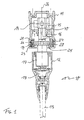
- a preferred embodiment of a sliding stack wall according to the invention is shown in cross section.
- the sliding stack wall 10 comprises a movable wall element 13, e.g. in the form of a glass pane or the like.
- the wall element 13 is bounded on the ceiling-side edge by a supporting profile 12 and supported in the lower part of this supporting profile 12.
- a first chassis 14 is fixed by means of a sliding block 18 that projects into the interior of a (designed as a hollow profile and mounted on the ceiling) running rail 11 and there merges into a carriage, with laterally mounted support rollers 15 on a Run level 40 within the track rail 11 is movable in the rail direction.
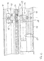
- a drive module 17 is mounted for the motor drive of the wall element 13, which - as shown in FIG. 2 can be seen - includes a horizontal within the support profile 12 lying electric drive motor 27.
- the drive motor 27 drives with its drive shaft 28 via a bevel gear 29 a rotatable about a vertical axis drive wheel 25 at.
- the drive wheel 25 is formed as a gear and arranged in the lower part of the running rail 11 below the running plane 40, where it meshes with a toothed belt 24 which is laterally vertically inserted into a side groove 20 of the running rail 11 and fixed there.
- the axis of action of the toothed belt 24 and the axes of the side guide rollers 16 are very close to each other. This ensures that even in curved pieces of the running rail and fixed mounting of the drive, the drive wheel 25 does not get out of engagement with the toothed belt 24.
- a second side groove 19 is provided on the other side of the median plane 26, in which a bus bar 21 extending in the rail direction is accommodated with two conductors 22 and 23 arranged vertically one above the other.
- the busbar conducts the current that is necessary for the operation of the drive motor 27.
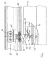
- the current is removed from the busbar 21 by current collectors 33, 34, which are fixed according to FIGS. 3 and 4 on a second chassis 30.
- the second chassis 30 is constructed in principle like the first chassis 14 and attached like the first chassis 14 by means of a sliding block 18 'in the corresponding groove of the support section 12.
- the guide rail 11 is mirror-symmetrical to the median plane 26.
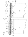
- the different arrangement of the support rollers 15 and 31 and side guide rollers 16 and 32 in the running rail 11 makes it possible to separate the running rail 11 in the central area in the parking area of the wall elements in two separate sub-rails and divide the sub-rails.
- the wall elements then run in the parking area with the one landing gear in the one sub-rail and the other chassis in the other sub-rail and can be placed individually obliquely or transversely and united in the majority in succession to a space-saving stack.
- the chassis 14 with the drive module 17 and the drive wheel 25 remains due to the arrangement of the rollers 15, 16 in that sub-rail, which also contains the toothed belt 24.
- the chassis 30 with the current collectors 33, 34 remains correspondingly in that sub-rail in which the busbar 21 is continued.
- the arrangement of the busbar 21 and the toothed belt 24 in the opposite side grooves 19, 20 of the rail profile is not only space-saving and therefore allows a very compact construction of the rail assembly. It also ensures that the same track 11 can be used in the same way and without restriction for both manually displaceable and automatically displaceable wall elements 13.
- the side grooves 19, 20 of the track can be left empty. Accordingly, wall elements are used which, although the same chassis 14, 30, but no drive module 17 and no current collectors 33, 34 have. If you want to switch to automatic operation later, simply slide bar 21 and a toothed belt 24 are inserted into the side grooves 19, 20 of the slide rail 11 and replaced in the wall elements existing chassis by those with electric motor drive and pantographs. Further changes are not necessary.
- the running rail 11 from the outset be equipped with busbar and / or timing belt. The transition from manual to automatic operation then only requires an exchange of the landing gear.
- the current collectors 33, 34 are equipped with individual contact elements 35 which are displaceably mounted in the current collectors 33, 34 perpendicularly to the busbar 21 and by means of a spring 36 against the conductors 22, 23 mounted insulated in the busbar 21 be pressed and form sliding contacts.
- the current removed by the current collectors 33, 34 is forwarded through power lines 38 to connection posts 39 fastened to a connection plate 37 and from there, for example, to the drive motor 27 via a plug-in contact 44 which can be detached for assembly or maintenance purposes.
- a (programmable) central controller 42 with appropriate computer and software capacity is provided according to FIG. 5, which via a data bus with local, microprocessor-equipped controls 43 exchanges data, which are housed in the individual wall elements 13 and control the movement and the actual state (position, travel speed, acceleration, braking, torque of the drive, etc.) of the respective wall element and monitor.
- the data transfer between the central controller 42 and the local controllers can be done in different ways, e.g. wireless, done.
- bus bar 21 itself as the data bus, which then also transports the power originating from a power supply 41 for the drive modules 17 of the wall elements 13 and also the data exchanged between the controllers 42 and 43.
- the response of a special wall element then takes place via an address code which uniquely characterizes the respective wall element.
- the local controls 43 are disposed between the pantographs in the landing gear 30 and the drive motors 27.
- the drive motor 27 may for example be equipped with a rotary encoder that allows to determine the distance traveled by the wall element by integrating the angle of rotation.
- current and voltage at the drive motor 27 can be measured and conclusions about the load, e.g. be pulled by a sudden obstacle in the travel of the wall element, which can be used to initiate an emergency shutdown.
Landscapes
- Power-Operated Mechanisms For Wings (AREA)
- Forms Removed On Construction Sites Or Auxiliary Members Thereof (AREA)
- Casting Support Devices, Ladles, And Melt Control Thereby (AREA)
- Making Paper Articles (AREA)
- Electrical Discharge Machining, Electrochemical Machining, And Combined Machining (AREA)
- Glass Compositions (AREA)
- Cylinder Crankcases Of Internal Combustion Engines (AREA)
- Rotary Pumps (AREA)
- Ship Loading And Unloading (AREA)
- Bearings For Parts Moving Linearly (AREA)
Claims (5)
- Cloison amovible (10) comprenant une pluralité de panneaux de mur (13) isolément amovibles, chaque panneau de mur (13) étant, à la hauteur de son bord supérieur tourné vers le plafond, délimité par un profilé support (12) s'étendant horizontalement, pouvant coulisser latéralement dans une glissière (11) commune disposée au dessus du profilé support (12) au moyen d'au moins un mécanisme de déplacement (14, 30) et présentant un mécanisme de commande propre (17) avec un moteur de commande (27) actionné à l'électricité, ce mécanisme (17) étant fixé sur le panneau de mur (13) et en prise avec la glissière (11) par l'intermédiaire de moyens d'entraînement (24, 25), caractérisée en ce que le moteur de commande (27) est disposé à l'intérieur du profilé support (12), en ce que l'arbre de commande (28) du moteur de commande (27) est disposé parallèlement à l'axe longitudinal du profilé support (12), en ce que les moyens d'entraînement comprennent une roue dentée (25) entraînée par le moteur de commande (27) et en prise avec un profil crénelé (24) s'étendant longitudinalement à l'intérieur de la glissière (11), en ce que le profil crénelé est une courroie dentée (24) intercalée dans la glissière (11), en ce que la roue dentée (25) peut tourner autour d'un axe vertical et s'engrène dans la courroie dentée (24) disposée verticalement et en ce que la transmission de force entre le moteur de commande (27) et la roue dentée (25) s'effectue par l'intermédiaire d'un engrenage conique (29), en ce que, pour alimenter en électricité le moteur de commande (27) à l'intérieur de la glissière (11), on a disposé une barre conductrice (21) s'étendant dans le sens longitudinal de la glissière (11) et en ce que chaque panneau de mur (13) présente un mécanisme de déplacement (30), lequel prélève sur la barre conductrice (21) au moyen de balais conducteurs (33, 34) fixés sur ce mécanisme (30) du courant électrique qu'il transmet au moteur de commande (27), et en ce que la glissière (11) présente la forme d'un rail symétriquement réfléchi par rapport à un plan médian (26) et dont l'intérieur présente un plan de roulement (40) sur lequel peuvent coulisser les mécanismes de déplacement (14, 30) au moyen de rouleaux porteurs (15, 31), en ce que deux gorges latérales (19, 20) ouvertes vers l'intérieur, s'étendant dans le sens longitudinal du rail et se faisant face sont formées en dessous du plan de roulement (40) et en ce que la barre conductrice (21) est disposée dans l'une (19) de ces gorges latérales alors que la courroie dentée (24) est disposée dans l'autre (20) .
- Cloison amovible selon la revendication 5
caractérisée en ce que chaque panneau de mur (13) présente deux mécanismes de déplacement disposés l'un derrière l'autre dans le sens de roulement, en ce que le panneau (13) est entraîné par l'intermédiaire du premier mécanisme de déplacement (14) alors que le second mécanisme de déplacement (30) assure la prise de courant. - Cloison amovible selon l'une des revendications 1 ou 2 caractérisée en ce que, dans chaque panneau de mur (13), il a été prévu une commande locale (43) à laquelle le moteur de commande (27) du panneau de mur correspondant est asservi et en ce que ces commandes locales (43) échangent des informations avec une commande centrale (42) par l'intermédiaire d'un bus de données.
- Cloison amovible selon la revendication 3
caractérisée en ce que la barre conductrice (21) sert de bus de données. - Cloison amovible selon l'une des revendications 3 et 4 caractérisée en ce que dans chaque panneau de mur (13), on a prévu des moyens qui enregistrent des informations relatives au déplacement du panneau de mur (13) et les transmettent à la commande locale (43) à des fins de traitement ultérieur.
Priority Applications (10)
| Application Number | Priority Date | Filing Date | Title |
|---|---|---|---|
| AT00126912T ATE247215T1 (de) | 1998-04-27 | 1998-04-27 | Schiebestapelwand sowie verfahren zu deren betrieb |
| EP98810365A EP0953706B2 (fr) | 1998-04-27 | 1998-04-27 | Paroi coulissante empilable |
| DE59809300T DE59809300D1 (de) | 1998-04-27 | 1998-04-27 | Schiebestapelwand sowie Verfahren zu deren Betrieb |
| ES98810365T ES2141695T5 (es) | 1998-04-27 | 1998-04-27 | Pared deslizable apilable. |
| EP00126912A EP1085159B1 (fr) | 1998-04-27 | 1998-04-27 | Paroi coulissante empilable et son procédé d'utilisation |
| ES00126912T ES2156838T3 (es) | 1998-04-27 | 1998-04-27 | Pared corredera apilable y procedimiento para su funcionamiento. |
| DE59804796T DE59804796D1 (de) | 1998-04-27 | 1998-04-27 | Schiebestapelwand |
| AT98810365T ATE220755T1 (de) | 1998-04-27 | 1998-04-27 | Schiebestapelwand |
| US09/299,146 US6233878B1 (en) | 1998-04-27 | 1999-04-26 | Sliding wall |
| JP11805599A JP3283010B2 (ja) | 1998-04-27 | 1999-04-26 | スライディングウォール |
Applications Claiming Priority (1)
| Application Number | Priority Date | Filing Date | Title |
|---|---|---|---|
| EP98810365A EP0953706B2 (fr) | 1998-04-27 | 1998-04-27 | Paroi coulissante empilable |
Related Child Applications (2)
| Application Number | Title | Priority Date | Filing Date |
|---|---|---|---|
| EP00126912A Division EP1085159B1 (fr) | 1998-04-27 | 1998-04-27 | Paroi coulissante empilable et son procédé d'utilisation |
| EP00126912.5 Division-Into | 2000-12-08 |
Publications (3)
| Publication Number | Publication Date |
|---|---|
| EP0953706A1 EP0953706A1 (fr) | 1999-11-03 |
| EP0953706B1 EP0953706B1 (fr) | 2002-07-17 |
| EP0953706B2 true EP0953706B2 (fr) | 2007-10-03 |
Family
ID=8236053
Family Applications (2)
| Application Number | Title | Priority Date | Filing Date |
|---|---|---|---|
| EP98810365A Expired - Lifetime EP0953706B2 (fr) | 1998-04-27 | 1998-04-27 | Paroi coulissante empilable |
| EP00126912A Expired - Lifetime EP1085159B1 (fr) | 1998-04-27 | 1998-04-27 | Paroi coulissante empilable et son procédé d'utilisation |
Family Applications After (1)
| Application Number | Title | Priority Date | Filing Date |
|---|---|---|---|
| EP00126912A Expired - Lifetime EP1085159B1 (fr) | 1998-04-27 | 1998-04-27 | Paroi coulissante empilable et son procédé d'utilisation |
Country Status (6)
| Country | Link |
|---|---|
| US (1) | US6233878B1 (fr) |
| EP (2) | EP0953706B2 (fr) |
| JP (1) | JP3283010B2 (fr) |
| AT (2) | ATE247215T1 (fr) |
| DE (2) | DE59804796D1 (fr) |
| ES (2) | ES2141695T5 (fr) |
Cited By (2)
| Publication number | Priority date | Publication date | Assignee | Title |
|---|---|---|---|---|
| DE102010040805A1 (de) | 2010-09-15 | 2012-03-15 | Bls Mobile Trennwandsysteme Gmbh & Co. Kg | Verfahren zur Steuerung einer Trennwand mit mehreren Wandelementen |
| US10151133B2 (en) | 2014-03-17 | 2018-12-11 | Gretsch-Unitas Gmbh Baubeschlaege | Sliding-door assembly |
Families Citing this family (57)
| Publication number | Priority date | Publication date | Assignee | Title |
|---|---|---|---|---|
| DE29880063U1 (de) | 1997-07-15 | 2000-04-27 | Geze Gmbh | Automatische Tür- oder Fensteranlage |
| DE19962074C2 (de) * | 1999-12-21 | 2001-10-25 | Dorma Gmbh & Co Kg | Gehäuse, insbesondere für Antriebe von automatisch und horizontal verfahrbaren Elementen |
| DE10101704B4 (de) | 2001-01-15 | 2012-11-08 | Geze Gmbh | Antrieb |
| DE10160915C1 (de) * | 2001-12-12 | 2003-06-18 | Kaba Gallenschuetz Gmbh | Antrieb für einen Schiebetürflügel |
| EP1344886A1 (fr) * | 2002-03-12 | 2003-09-17 | Maria Krimmel | Appareil pour portes coulissantes |
| EP1552096B1 (fr) * | 2002-07-05 | 2013-04-17 | Hawa Ag | Dispositif pour elements de separation coulissants, chariot et element de separation |
| EP1413541A1 (fr) * | 2002-10-22 | 2004-04-28 | BC Lift A/S | Rail de guidage pour ascenseur d'escalier |
| DE10300821A1 (de) * | 2003-01-10 | 2004-07-29 | Dorma Gmbh + Co. Kg | Mobile Trennwand |
| DE10324532B4 (de) * | 2003-05-28 | 2005-07-21 | Dorma Gmbh + Co. Kg | Messsystem zur Bestimmung einer absoluten Position eines sich entlang einer Führungsschiene bewegenden Elementes, Horizontalschiebewand und Element für eine Horizontalschiebewand |
| DE10337122B4 (de) * | 2003-08-11 | 2007-10-11 | Manfred Josef Wallner | Hängekranbahn und Hängekranbahnprofil |
| KR100623111B1 (ko) * | 2004-09-21 | 2006-09-19 | 오티스 엘리베이터 컴파니 | 중실체의 도어 프레임 및 이를 구비한 자동 도어 조립체 |
| EP1640543B1 (fr) * | 2004-09-23 | 2016-06-01 | Hawa Ag | Dispositif de propulsion pour un élément de séparation coulissant |
| EP1657393B1 (fr) * | 2004-11-12 | 2014-03-19 | Hawa Ag | Dispositif avec des éléments de cloison de séparation contrôlable et procédé de commande |
| US20060144529A1 (en) * | 2005-01-04 | 2006-07-06 | Emerge Technologies, Inc. | Automated door openers |
| DE102006007511A1 (de) * | 2005-06-14 | 2006-12-21 | Wilfried Boldt | Schienengeführtes Mobilwandelement |
| DE102005048157A1 (de) * | 2005-10-06 | 2007-04-19 | Dorma Gmbh + Co. Kg | Mobile Trennwand |
| DE102005048155A1 (de) * | 2005-10-06 | 2007-04-19 | Dorma Gmbh + Co. Kg | Mobile Trennwand |
| JP2009523936A (ja) * | 2006-01-18 | 2009-06-25 | ソンチョル キム | 空間仕切り装置 |
| KR100758659B1 (ko) | 2006-04-25 | 2007-09-13 | 김성철 | 이동식 커튼월 |
| US8590233B2 (en) * | 2006-11-09 | 2013-11-26 | Gary Sprague | Stacking wall panel system and methods of installation and use |
| DE102006054927A1 (de) * | 2006-11-22 | 2008-07-31 | BLASI - GMBH Automatische Türanlagen | Schiebetür |
| DE102007033119A1 (de) * | 2007-07-13 | 2009-01-15 | Wilfried Boldt | Stromleiste und Führungsschiene für schienengeführte Mobilwandelemente |
| US8251784B2 (en) * | 2008-06-09 | 2012-08-28 | International Business Machines Corporation | System and method to route airflow through dynamically changing ducts |
| DE102008027821A1 (de) * | 2008-06-11 | 2009-12-17 | Dorma Gmbh + Co. Kg | Trennwand aus transparenten Wandelementen |
| US20090308548A1 (en) * | 2008-06-16 | 2009-12-17 | Tramontina Paul F | Temporary partition curtain |
| DE102008028831C5 (de) * | 2008-06-19 | 2013-06-06 | Dorma Gmbh + Co. Kg | Antriebssystem zum Antrieb und zur Führung eines Wandelementes für ein Raumtrennwandsystem |
| DE202009000929U1 (de) * | 2009-01-24 | 2009-03-26 | Sommer Antriebs- Und Funktechnik Gmbh | Antriebssystem für ein Tor |
| DE102009011947A1 (de) * | 2009-03-10 | 2010-09-16 | Dorma Gmbh + Co. Kg | Antriebssystem zum Antrieb und zur Führung eines Wandelelementes für ein Raumtrennwandsystem |
| DE102009014130A1 (de) | 2009-03-24 | 2010-09-30 | Dorma Gmbh + Co. Kg | Steuerungssystem für eine Trennwandanlage |
| DE202009009548U1 (de) * | 2009-07-10 | 2009-09-10 | Dorma Gmbh + Co. Kg | Deckenschienensystem zur Führung von Wandelementen |
| US9353568B2 (en) * | 2009-08-17 | 2016-05-31 | Won-Door Corporation | Methods, apparatuses, and systems for driving a movable partition |
| US8365796B2 (en) | 2010-04-12 | 2013-02-05 | Won-Door Corporation | Methods, apparatuses, and systems for movable partitions |
| US8978905B2 (en) | 2010-07-02 | 2015-03-17 | Liko Research & Development Ab | Lift systems with continuous in-rail charging |
| DE102010040802B4 (de) | 2010-09-15 | 2013-09-19 | Bls Mobile Trennwandsysteme Gmbh & Co. Kg | Verfahren zur Steuerung einer Trennwand mit mehreren Wandelementen |
| DE102010040801B4 (de) | 2010-09-15 | 2016-03-10 | Bls Mobile Trennwandsysteme Gmbh & Co. Kg | Trennwand mit mehreren verfahrbaren Wandelementen und ein Verfahren zur Steuerung dieser Trennwand |
| FR2968346A1 (fr) * | 2010-12-02 | 2012-06-08 | Noval | Dispositif d'occultation coulissant autotracte |
| US8407941B2 (en) * | 2011-03-14 | 2013-04-02 | Door & Window Hardware Co. | Driving device for driving two door panels to synchronously move |
| WO2013123560A1 (fr) * | 2012-02-21 | 2013-08-29 | Jillian Jolly | Agencement de cadre mobile |
| DE102012103130B4 (de) * | 2012-04-12 | 2016-07-07 | Ws Beteiligungs Gmbh | Vorrichtung zum Tragen und zum Befördern von Waren, ein Trägerelement dafür sowie Fördersystem mit einer Mehrzahl solcher Vorrichtungen |
| US9222255B2 (en) * | 2013-08-01 | 2015-12-29 | Urbaneer LLC | Apparatus and method for reconfigurable space |
| DE102013223459A1 (de) * | 2013-08-19 | 2015-02-19 | Kl Megla Gmbh | Tür mit elektrischer Kontaktierung |
| CA2842446C (fr) * | 2014-02-10 | 2020-04-14 | Dynamic Closures Corp. | Chariot pour porte pliante |
| EP2947250A1 (fr) | 2014-03-17 | 2015-11-25 | Gretsch-Unitas GmbH Baubeschläge | Dispositif de porte coulissante |
| US10196815B2 (en) | 2014-05-28 | 2019-02-05 | Advanced Equipment Corporation | Wall partition movement systems and methods |
| US9359804B2 (en) * | 2014-05-28 | 2016-06-07 | Advanced Equipment Corporation | Wall partition movement systems and methods |
| CN106088889A (zh) * | 2016-08-16 | 2016-11-09 | 广州市西恩电气设备有限公司 | 一种中心旋转的隔断门 |
| CN106088951B (zh) * | 2016-08-16 | 2018-10-23 | 广州市西恩电气设备有限公司 | 一种自动平移的隔断门 |
| CN107083904B (zh) * | 2017-06-16 | 2019-01-15 | 中国矿业大学 | 节约空间的可全开式移动门窗系统 |
| US10822857B2 (en) * | 2017-07-03 | 2020-11-03 | Hall Labs Llc | Retrofittable motorized gear sliding window or door system |
| US10995538B2 (en) * | 2017-07-03 | 2021-05-04 | Hall Labs Llc | Retrofittable motorized pulley sliding window or door system |
| US10995537B2 (en) * | 2017-11-27 | 2021-05-04 | Hall Labs Llc | Motorized gear sliding window or door system |
| FR3071271B1 (fr) * | 2017-09-21 | 2020-11-06 | Accoplas Soc Gen De Fermetures | Dispositif d'obstruction coulissant et motorise pour ouverture de facade |
| US10808446B2 (en) * | 2017-11-24 | 2020-10-20 | Hall Labs Llc | Pulley-driven automated window or door system |
| US20190309562A1 (en) * | 2018-04-05 | 2019-10-10 | David R. Hall | Automated Window System with Wireless Control |
| CN110242095B (zh) * | 2019-07-09 | 2024-06-21 | 衡水通广通信导航设备有限公司 | 雷达塔智能封闭系统及其施工方法 |
| US11421418B2 (en) * | 2019-12-20 | 2022-08-23 | Universal City Studios Llc | Truss with integrated wiring |
| RS64518B1 (sr) * | 2020-03-20 | 2023-09-29 | Gretsch Unitas Gmbh Baubeschlaege | Sklop kliznih vrata |
Family Cites Families (20)
| Publication number | Priority date | Publication date | Assignee | Title |
|---|---|---|---|---|
| DE1036105B (de) * | 1955-06-13 | 1958-08-07 | Rudolf Stoerzbach | Laufwerk fuer schiebbare Fluegel von Tueren, Fenstern od. dgl. |
| DE2404875C3 (de) * | 1974-02-01 | 1978-05-18 | Fa. Justin Hueppe, 2900 Oldenburg | Raumtrennwand aus versetzbaren starren Wandelementen |
| DE2643905C2 (de) | 1976-09-29 | 1978-10-19 | Siemens Ag, 1000 Berlin Und 8000 Muenchen | Raumteilungs-Wandelement mit motorischem Antrieb |
| DE2910185A1 (de) | 1979-03-15 | 1980-09-25 | Ver Baubeschlag Gretsch Co | Tuer od.dgl. mit einem motorisch verschiebbaren blatt |
| DE3147273A1 (de) * | 1981-11-28 | 1983-07-28 | Justin Hüppe GmbH, 2900 Oldenburg | Raumtrennwand |
| DE3626321A1 (de) * | 1986-08-02 | 1988-02-04 | Manfred Albers | Trennvorrichtung in reinraeumen |
| DE8803188U1 (de) * | 1988-03-09 | 1988-09-15 | Dorma-Glas Gesellschaft für Glastürbeschläge und -Konstruktionen mbH, 4902 Bad Salzuflen | Schiebetürvorrichtung |
| WO1992013300A1 (fr) * | 1991-01-25 | 1992-08-06 | Gilgen Ag | Systeme de commande electronique pour une porte automatique |
| DE9214915U1 (de) * | 1992-11-03 | 1993-02-25 | abopart Viol und Partner GmbH & Co KG, 2903 Bad Zwischenahn | Versetzbare Trennwand mit mehreren plattenförmigen Wandelementen |
| DE59400492D1 (de) * | 1993-05-25 | 1996-09-19 | Rosconi Ag | Mobile Trennwand |
| US5577348A (en) * | 1993-05-25 | 1996-11-26 | Rosconi Ag | Partition wall with sliding termination panel |
| US5544462A (en) * | 1993-11-02 | 1996-08-13 | Dorma Gmbh + Co. Kg | Movable wall system |
| DE19541758C2 (de) * | 1995-11-09 | 1998-07-02 | Teufelbeschlag Gmbh | Feststell- und Verriegelungsvorrichtung für schwenk- und verschiebbare Türen |
| IT1282310B1 (it) * | 1995-12-22 | 1998-03-16 | Kassian Estfeller & Co Sas Kg | Dispositivo di azionamento per pannelli di pareti componibili. |
| CH689233A5 (de) * | 1996-05-07 | 1998-12-31 | Dorma Tuerautomatik Ag | Schiebewand |
| DE19733381A1 (de) * | 1996-08-01 | 1998-03-26 | Geze Gmbh & Co | Flügel für ein Fenster, eine Tür o. dgl. sowie Trage- und/oder Randabschlußelement für einen Flügel |
| DE29708147U1 (de) * | 1997-05-07 | 1997-07-10 | Dorma Gmbh + Co. Kg, 58256 Ennepetal | Antrieb für ein in oder an einer Führungsschiene geführtes Laufwerk |
| DE19746208C2 (de) * | 1997-10-20 | 2000-04-06 | Dorma Gmbh & Co Kg | Laufschiene für ein Laufwerk für eine hängend gelagerte Trennwand |
| DE19819279C1 (de) | 1998-04-30 | 1999-03-25 | Dorma Gmbh & Co Kg | Antriebssystem für ein Trennwandsystem |
| US6018915A (en) * | 1999-01-29 | 2000-02-01 | Pci Industries, Inc. | Sliding and locking wall panels |
-
1998
- 1998-04-27 AT AT00126912T patent/ATE247215T1/de active
- 1998-04-27 AT AT98810365T patent/ATE220755T1/de active
- 1998-04-27 EP EP98810365A patent/EP0953706B2/fr not_active Expired - Lifetime
- 1998-04-27 EP EP00126912A patent/EP1085159B1/fr not_active Expired - Lifetime
- 1998-04-27 ES ES98810365T patent/ES2141695T5/es not_active Expired - Lifetime
- 1998-04-27 DE DE59804796T patent/DE59804796D1/de not_active Expired - Lifetime
- 1998-04-27 ES ES00126912T patent/ES2156838T3/es not_active Expired - Lifetime
- 1998-04-27 DE DE59809300T patent/DE59809300D1/de not_active Expired - Lifetime
-
1999
- 1999-04-26 US US09/299,146 patent/US6233878B1/en not_active Expired - Fee Related
- 1999-04-26 JP JP11805599A patent/JP3283010B2/ja not_active Expired - Lifetime
Cited By (3)
| Publication number | Priority date | Publication date | Assignee | Title |
|---|---|---|---|---|
| DE102010040805A1 (de) | 2010-09-15 | 2012-03-15 | Bls Mobile Trennwandsysteme Gmbh & Co. Kg | Verfahren zur Steuerung einer Trennwand mit mehreren Wandelementen |
| DE102010040805B4 (de) * | 2010-09-15 | 2016-03-10 | Bls Mobile Trennwandsysteme Gmbh & Co. Kg | Verfahren zur Steuerung einer Trennwand mit mehreren Wandelementen |
| US10151133B2 (en) | 2014-03-17 | 2018-12-11 | Gretsch-Unitas Gmbh Baubeschlaege | Sliding-door assembly |
Also Published As
| Publication number | Publication date |
|---|---|
| EP0953706A1 (fr) | 1999-11-03 |
| ATE247215T1 (de) | 2003-08-15 |
| ES2141695T5 (es) | 2008-03-01 |
| JP3283010B2 (ja) | 2002-05-20 |
| EP1085159B1 (fr) | 2003-08-13 |
| ES2156838T1 (es) | 2001-08-01 |
| ES2156838T3 (es) | 2004-04-16 |
| EP1085159A2 (fr) | 2001-03-21 |
| DE59809300D1 (de) | 2003-09-18 |
| ES2141695T1 (es) | 2000-04-01 |
| JP2000027534A (ja) | 2000-01-25 |
| ES2141695T3 (es) | 2003-02-16 |
| EP1085159A3 (fr) | 2002-01-16 |
| ATE220755T1 (de) | 2002-08-15 |
| EP0953706B1 (fr) | 2002-07-17 |
| DE59804796D1 (de) | 2002-08-22 |
| US6233878B1 (en) | 2001-05-22 |
Similar Documents
| Publication | Publication Date | Title |
|---|---|---|
| EP0953706B2 (fr) | Paroi coulissante empilable | |
| DE102008028831C5 (de) | Antriebssystem zum Antrieb und zur Führung eines Wandelementes für ein Raumtrennwandsystem | |
| EP0556595B1 (fr) | Système de transport de passagers | |
| EP0846214B1 (fr) | Paroi coulissante | |
| DE2404875C3 (de) | Raumtrennwand aus versetzbaren starren Wandelementen | |
| DE3612500A1 (de) | Wagen-transportanordnung | |
| EP0597208B1 (fr) | Cloison amovible à plusieurs panneaux de murs | |
| DE202020104082U1 (de) | Tür oder Fenster mit einem verschiebbaren Flügel als Schiebeflügel oder verschiebbaren Hebe-Schiebeflügel und einer Antriebsvorrichtung | |
| DE3520838C2 (fr) | ||
| EP2476842A2 (fr) | Installation de portes coulissantes | |
| EP2406450B1 (fr) | Système d'entraînement pour l'entraînement et le guidage d'un élément de cloison pour un système de cloison de séparation d'espace | |
| DE3418866A1 (de) | Untergurt-elektrohaengebahn | |
| DE3103162A1 (de) | Foerdervorrichtung fuer lasten | |
| DE102005002179A1 (de) | Flügelanordnung mit Fahrflügel und Festflügel | |
| DE2942839A1 (de) | Fahrerloser, elektromotorisch angetriebener transportwagen | |
| EP1437468A1 (fr) | Paroi de séparation mobile | |
| DE2146680A1 (de) | Elektrische Stromabnahmevorrichtung, insbesondere für Fahrzeuge mit sehr hoher Geschwindigkeit | |
| CH665676A5 (de) | Bewegbares wandelement. | |
| DE10060865B4 (de) | Schiebewand | |
| DE2451735A1 (de) | Antriebs- und aufhaengevorrichtung fuer doppelschwenkschiebetueren | |
| DE3425999C2 (fr) | ||
| DE3437457A1 (de) | Vorhangschiene | |
| EP0881343A1 (fr) | Appareil de parcage pour automobiles avec au moins deux places de parking superposées | |
| WO2006074784A1 (fr) | Chassis muni d'une porte coulissante | |
| DE1959192C3 (de) | Vorrichtung zum Verschieben von Parkplattformen |
Legal Events
| Date | Code | Title | Description |
|---|---|---|---|
| PUAI | Public reference made under article 153(3) epc to a published international application that has entered the european phase |
Free format text: ORIGINAL CODE: 0009012 |
|
| AK | Designated contracting states |
Kind code of ref document: A1 Designated state(s): AT CH DE ES FR GB IT LI NL SE |
|
| AX | Request for extension of the european patent |
Free format text: AL;LT;LV;MK;RO;SI |
|
| ITCL | It: translation for ep claims filed |
Representative=s name: STUDIO CONSUL.BREVETTUALE S.R.L. |
|
| GBC | Gb: translation of claims filed (gb section 78(7)/1977) | ||
| EL | Fr: translation of claims filed | ||
| 17P | Request for examination filed |
Effective date: 20000107 |
|
| REG | Reference to a national code |
Ref country code: ES Ref legal event code: BA2A Ref document number: 2141695 Country of ref document: ES Kind code of ref document: T1 |
|
| TCNL | Nl: translation of patent claims filed | ||
| AKX | Designation fees paid |
Free format text: AT CH DE ES FR GB IT LI NL SE |
|
| GRAG | Despatch of communication of intention to grant |
Free format text: ORIGINAL CODE: EPIDOS AGRA |
|
| 17Q | First examination report despatched |
Effective date: 20010607 |
|
| GRAG | Despatch of communication of intention to grant |
Free format text: ORIGINAL CODE: EPIDOS AGRA |
|
| GRAH | Despatch of communication of intention to grant a patent |
Free format text: ORIGINAL CODE: EPIDOS IGRA |
|
| GRAH | Despatch of communication of intention to grant a patent |
Free format text: ORIGINAL CODE: EPIDOS IGRA |
|
| GRAA | (expected) grant |
Free format text: ORIGINAL CODE: 0009210 |
|
| AK | Designated contracting states |
Kind code of ref document: B1 Designated state(s): AT CH DE ES FR GB IT LI NL SE |
|
| REF | Corresponds to: |
Ref document number: 220755 Country of ref document: AT Date of ref document: 20020815 Kind code of ref document: T |
|
| REG | Reference to a national code |
Ref country code: GB Ref legal event code: FG4D Free format text: NOT ENGLISH |
|
| REG | Reference to a national code |
Ref country code: CH Ref legal event code: EP |
|
| GBT | Gb: translation of ep patent filed (gb section 77(6)(a)/1977) |
Effective date: 20020717 |
|
| REG | Reference to a national code |
Ref country code: CH Ref legal event code: NV Representative=s name: ISLER & PEDRAZZINI AG |
|
| REF | Corresponds to: |
Ref document number: 59804796 Country of ref document: DE Date of ref document: 20020822 |
|
| ET | Fr: translation filed | ||
| REG | Reference to a national code |
Ref country code: ES Ref legal event code: FG2A Ref document number: 2141695 Country of ref document: ES Kind code of ref document: T3 |
|
| PLBQ | Unpublished change to opponent data |
Free format text: ORIGINAL CODE: EPIDOS OPPO |
|
| PLBI | Opposition filed |
Free format text: ORIGINAL CODE: 0009260 |
|
| PLBF | Reply of patent proprietor to notice(s) of opposition |
Free format text: ORIGINAL CODE: EPIDOS OBSO |
|
| 26 | Opposition filed |
Opponent name: GRETSCH-UNITAS GMBH,BAUBESCHLAEGE Effective date: 20030416 Opponent name: GEZE GMBH Effective date: 20030416 Opponent name: DR.- ING. PETER BERG Effective date: 20030414 |
|
| NLR1 | Nl: opposition has been filed with the epo |
Opponent name: GRETSCH-UNITAS GMBH, BAUBESCHLAEGE Opponent name: GEZE GMBH Opponent name: DR.- ING. PETER BERG |
|
| PLBB | Reply of patent proprietor to notice(s) of opposition received |
Free format text: ORIGINAL CODE: EPIDOSNOBS3 |
|
| APBP | Date of receipt of notice of appeal recorded |
Free format text: ORIGINAL CODE: EPIDOSNNOA2O |
|
| APBM | Appeal reference recorded |
Free format text: ORIGINAL CODE: EPIDOSNREFNO |
|
| PLAQ | Examination of admissibility of opposition: information related to despatch of communication + time limit deleted |
Free format text: ORIGINAL CODE: EPIDOSDOPE2 |
|
| PLAR | Examination of admissibility of opposition: information related to receipt of reply deleted |
Free format text: ORIGINAL CODE: EPIDOSDOPE4 |
|
| PLBQ | Unpublished change to opponent data |
Free format text: ORIGINAL CODE: EPIDOS OPPO |
|
| PLAB | Opposition data, opponent's data or that of the opponent's representative modified |
Free format text: ORIGINAL CODE: 0009299OPPO |
|
| APBM | Appeal reference recorded |
Free format text: ORIGINAL CODE: EPIDOSNREFNO |
|
| APBP | Date of receipt of notice of appeal recorded |
Free format text: ORIGINAL CODE: EPIDOSNNOA2O |
|
| R26 | Opposition filed (corrected) |
Opponent name: GRETSCH-UNITAS GMBH,BAUBESCHLAEGE Effective date: 20030416 Opponent name: GEZE GMBH Effective date: 20030416 Opponent name: DR.- ING. PETER BERG Effective date: 20030414 |
|
| APBQ | Date of receipt of statement of grounds of appeal recorded |
Free format text: ORIGINAL CODE: EPIDOSNNOA3O |
|
| NLR1 | Nl: opposition has been filed with the epo |
Opponent name: GRETSCH-UNITAS GMBH, BAUBESCHLAEGE Opponent name: GEZE GMBH Opponent name: DR.- ING. PETER BERG |
|
| APAH | Appeal reference modified |
Free format text: ORIGINAL CODE: EPIDOSCREFNO |
|
| APAH | Appeal reference modified |
Free format text: ORIGINAL CODE: EPIDOSCREFNO |
|
| APBU | Appeal procedure closed |
Free format text: ORIGINAL CODE: EPIDOSNNOA9O |
|
| PUAH | Patent maintained in amended form |
Free format text: ORIGINAL CODE: 0009272 |
|
| STAA | Information on the status of an ep patent application or granted ep patent |
Free format text: STATUS: PATENT MAINTAINED AS AMENDED |
|
| REG | Reference to a national code |
Ref country code: CH Ref legal event code: PCAR Free format text: ISLER & PEDRAZZINI AG;POSTFACH 1772;8027 ZUERICH (CH) |
|
| 27A | Patent maintained in amended form |
Effective date: 20071003 |
|
| AK | Designated contracting states |
Kind code of ref document: B2 Designated state(s): AT CH DE ES FR GB IT LI NL SE |
|
| REG | Reference to a national code |
Ref country code: CH Ref legal event code: AEN Free format text: AUFRECHTERHALTUNG DES PATENTES IN GEAENDERTER FORM |
|
| GBTA | Gb: translation of amended ep patent filed (gb section 77(6)(b)/1977) | ||
| NLR2 | Nl: decision of opposition |
Effective date: 20071003 |
|
| REG | Reference to a national code |
Ref country code: SE Ref legal event code: RPEO |
|
| REG | Reference to a national code |
Ref country code: ES Ref legal event code: DC2A Date of ref document: 20071105 Kind code of ref document: T5 |
|
| NLR3 | Nl: receipt of modified translations in the netherlands language after an opposition procedure | ||
| ET3 | Fr: translation filed ** decision concerning opposition | ||
| PLAB | Opposition data, opponent's data or that of the opponent's representative modified |
Free format text: ORIGINAL CODE: 0009299OPPO |
|
| PGFP | Annual fee paid to national office [announced via postgrant information from national office to epo] |
Ref country code: NL Payment date: 20120425 Year of fee payment: 15 Ref country code: CH Payment date: 20120419 Year of fee payment: 15 Ref country code: DE Payment date: 20120420 Year of fee payment: 15 |
|
| PGFP | Annual fee paid to national office [announced via postgrant information from national office to epo] |
Ref country code: SE Payment date: 20120418 Year of fee payment: 15 Ref country code: FR Payment date: 20120507 Year of fee payment: 15 Ref country code: GB Payment date: 20120419 Year of fee payment: 15 |
|
| PGFP | Annual fee paid to national office [announced via postgrant information from national office to epo] |
Ref country code: IT Payment date: 20120426 Year of fee payment: 15 |
|
| PGFP | Annual fee paid to national office [announced via postgrant information from national office to epo] |
Ref country code: ES Payment date: 20120424 Year of fee payment: 15 |
|
| PGFP | Annual fee paid to national office [announced via postgrant information from national office to epo] |
Ref country code: AT Payment date: 20120411 Year of fee payment: 15 |
|
| REG | Reference to a national code |
Ref country code: NL Ref legal event code: V1 Effective date: 20131101 |
|
| REG | Reference to a national code |
Ref country code: CH Ref legal event code: PL |
|
| REG | Reference to a national code |
Ref country code: SE Ref legal event code: EUG |
|
| REG | Reference to a national code |
Ref country code: AT Ref legal event code: MM01 Ref document number: 220755 Country of ref document: AT Kind code of ref document: T Effective date: 20130430 |
|
| GBPC | Gb: european patent ceased through non-payment of renewal fee |
Effective date: 20130427 |
|
| PG25 | Lapsed in a contracting state [announced via postgrant information from national office to epo] |
Ref country code: LI Free format text: LAPSE BECAUSE OF NON-PAYMENT OF DUE FEES Effective date: 20130430 Ref country code: SE Free format text: LAPSE BECAUSE OF NON-PAYMENT OF DUE FEES Effective date: 20130428 Ref country code: GB Free format text: LAPSE BECAUSE OF NON-PAYMENT OF DUE FEES Effective date: 20130427 Ref country code: AT Free format text: LAPSE BECAUSE OF NON-PAYMENT OF DUE FEES Effective date: 20130430 Ref country code: CH Free format text: LAPSE BECAUSE OF NON-PAYMENT OF DUE FEES Effective date: 20130430 Ref country code: DE Free format text: LAPSE BECAUSE OF NON-PAYMENT OF DUE FEES Effective date: 20131101 |
|
| REG | Reference to a national code |
Ref country code: FR Ref legal event code: ST Effective date: 20131231 |
|
| REG | Reference to a national code |
Ref country code: DE Ref legal event code: R119 Ref document number: 59804796 Country of ref document: DE Effective date: 20131101 |
|
| PG25 | Lapsed in a contracting state [announced via postgrant information from national office to epo] |
Ref country code: NL Free format text: LAPSE BECAUSE OF NON-PAYMENT OF DUE FEES Effective date: 20131101 Ref country code: FR Free format text: LAPSE BECAUSE OF NON-PAYMENT OF DUE FEES Effective date: 20130430 Ref country code: IT Free format text: LAPSE BECAUSE OF NON-PAYMENT OF DUE FEES Effective date: 20130427 |
|
| REG | Reference to a national code |
Ref country code: ES Ref legal event code: FD2A Effective date: 20140611 |
|
| PG25 | Lapsed in a contracting state [announced via postgrant information from national office to epo] |
Ref country code: ES Free format text: LAPSE BECAUSE OF NON-PAYMENT OF DUE FEES Effective date: 20130428 |