EP2476842A2 - Installation de portes coulissantes - Google Patents
Installation de portes coulissantes Download PDFInfo
- Publication number
- EP2476842A2 EP2476842A2 EP11009497A EP11009497A EP2476842A2 EP 2476842 A2 EP2476842 A2 EP 2476842A2 EP 11009497 A EP11009497 A EP 11009497A EP 11009497 A EP11009497 A EP 11009497A EP 2476842 A2 EP2476842 A2 EP 2476842A2
- Authority
- EP
- European Patent Office
- Prior art keywords
- door
- wings
- receiving spaces
- profile
- pair
- Prior art date
- Legal status (The legal status is an assumption and is not a legal conclusion. Google has not performed a legal analysis and makes no representation as to the accuracy of the status listed.)
- Withdrawn
Links
Images


Classifications
-
- E—FIXED CONSTRUCTIONS
- E05—LOCKS; KEYS; WINDOW OR DOOR FITTINGS; SAFES
- E05D—HINGES OR SUSPENSION DEVICES FOR DOORS, WINDOWS OR WINGS
- E05D15/00—Suspension arrangements for wings
- E05D15/06—Suspension arrangements for wings for wings sliding horizontally more or less in their own plane
- E05D15/0621—Details, e.g. suspension or supporting guides
- E05D15/0626—Details, e.g. suspension or supporting guides for wings suspended at the top
- E05D15/0652—Tracks
-
- E—FIXED CONSTRUCTIONS
- E05—LOCKS; KEYS; WINDOW OR DOOR FITTINGS; SAFES
- E05D—HINGES OR SUSPENSION DEVICES FOR DOORS, WINDOWS OR WINGS
- E05D15/00—Suspension arrangements for wings
- E05D15/06—Suspension arrangements for wings for wings sliding horizontally more or less in their own plane
- E05D15/08—Suspension arrangements for wings for wings sliding horizontally more or less in their own plane consisting of two or more independent parts movable each in its own guides
-
- E—FIXED CONSTRUCTIONS
- E05—LOCKS; KEYS; WINDOW OR DOOR FITTINGS; SAFES
- E05F—DEVICES FOR MOVING WINGS INTO OPEN OR CLOSED POSITION; CHECKS FOR WINGS; WING FITTINGS NOT OTHERWISE PROVIDED FOR, CONCERNED WITH THE FUNCTIONING OF THE WING
- E05F15/00—Power-operated mechanisms for wings
- E05F15/60—Power-operated mechanisms for wings using electrical actuators
-
- E—FIXED CONSTRUCTIONS
- E05—LOCKS; KEYS; WINDOW OR DOOR FITTINGS; SAFES
- E05Y—INDEXING SCHEME ASSOCIATED WITH SUBCLASSES E05D AND E05F, RELATING TO CONSTRUCTION ELEMENTS, ELECTRIC CONTROL, POWER SUPPLY, POWER SIGNAL OR TRANSMISSION, USER INTERFACES, MOUNTING OR COUPLING, DETAILS, ACCESSORIES, AUXILIARY OPERATIONS NOT OTHERWISE PROVIDED FOR, APPLICATION THEREOF
- E05Y2201/00—Constructional elements; Accessories therefor
- E05Y2201/60—Suspension or transmission members; Accessories therefor
- E05Y2201/622—Suspension or transmission members elements
- E05Y2201/684—Rails; Tracks
-
- E—FIXED CONSTRUCTIONS
- E05—LOCKS; KEYS; WINDOW OR DOOR FITTINGS; SAFES
- E05Y—INDEXING SCHEME ASSOCIATED WITH SUBCLASSES E05D AND E05F, RELATING TO CONSTRUCTION ELEMENTS, ELECTRIC CONTROL, POWER SUPPLY, POWER SIGNAL OR TRANSMISSION, USER INTERFACES, MOUNTING OR COUPLING, DETAILS, ACCESSORIES, AUXILIARY OPERATIONS NOT OTHERWISE PROVIDED FOR, APPLICATION THEREOF
- E05Y2400/00—Electronic control; Electrical power; Power supply; Power or signal transmission; User interfaces
- E05Y2400/10—Electronic control
- E05Y2400/44—Sensors not directly associated with the wing movement
-
- E—FIXED CONSTRUCTIONS
- E05—LOCKS; KEYS; WINDOW OR DOOR FITTINGS; SAFES
- E05Y—INDEXING SCHEME ASSOCIATED WITH SUBCLASSES E05D AND E05F, RELATING TO CONSTRUCTION ELEMENTS, ELECTRIC CONTROL, POWER SUPPLY, POWER SIGNAL OR TRANSMISSION, USER INTERFACES, MOUNTING OR COUPLING, DETAILS, ACCESSORIES, AUXILIARY OPERATIONS NOT OTHERWISE PROVIDED FOR, APPLICATION THEREOF
- E05Y2800/00—Details, accessories and auxiliary operations not otherwise provided for
- E05Y2800/26—Form or shape
- E05Y2800/266—Form or shape curved
-
- E—FIXED CONSTRUCTIONS
- E05—LOCKS; KEYS; WINDOW OR DOOR FITTINGS; SAFES
- E05Y—INDEXING SCHEME ASSOCIATED WITH SUBCLASSES E05D AND E05F, RELATING TO CONSTRUCTION ELEMENTS, ELECTRIC CONTROL, POWER SUPPLY, POWER SIGNAL OR TRANSMISSION, USER INTERFACES, MOUNTING OR COUPLING, DETAILS, ACCESSORIES, AUXILIARY OPERATIONS NOT OTHERWISE PROVIDED FOR, APPLICATION THEREOF
- E05Y2800/00—Details, accessories and auxiliary operations not otherwise provided for
- E05Y2800/26—Form or shape
- E05Y2800/27—Profiles; Strips
- E05Y2800/272—Profiles; Strips hollow
- E05Y2800/276—U-shaped
-
- E—FIXED CONSTRUCTIONS
- E05—LOCKS; KEYS; WINDOW OR DOOR FITTINGS; SAFES
- E05Y—INDEXING SCHEME ASSOCIATED WITH SUBCLASSES E05D AND E05F, RELATING TO CONSTRUCTION ELEMENTS, ELECTRIC CONTROL, POWER SUPPLY, POWER SIGNAL OR TRANSMISSION, USER INTERFACES, MOUNTING OR COUPLING, DETAILS, ACCESSORIES, AUXILIARY OPERATIONS NOT OTHERWISE PROVIDED FOR, APPLICATION THEREOF
- E05Y2900/00—Application of doors, windows, wings or fittings thereof
- E05Y2900/10—Application of doors, windows, wings or fittings thereof for buildings or parts thereof
- E05Y2900/13—Type of wing
- E05Y2900/132—Doors
Definitions
- the invention relates to a sliding door system and in particular an automatic, so powered sliding door system, the sliding door leaves are thus moved by a motor.
- Such door systems are known per se. They are mounted by the door leaf suspension is attached to a door reveal, which is formed for example by means of an opening of a building wall or a fixed frame profile.
- door panels for example, are usually opened and closed manually in restaurants between the guest room and the kitchen area.
- double swing door systems use, which are provided in each case only for one or both passage direction (s).
- a thereby required manual door operation by the service personnel can bring hygienic problems.
- Another problem of such door systems is the risk of collision due to the door area, which can still be frequented in both directions. This is particularly large when a person approaches a door opening in their direction and the door wings are opaque, so that it is difficult or impossible to recognize the door opening and respond in a timely manner.
- the object of the invention is to at least reduce the disadvantages of the prior art.
- a sliding door system has at least two door leaves.
- the system also includes a guide profile with at least two receiving spaces.
- a respective one of a pair of associated ones of the at least two door leaves is received with a portion guided along a respective travel path.
- the receiving spaces thus define the course of the travel path of each recorded door leaf.
- the resulting two traverse paths extend such that the door wings of this pair of wings received are arranged independently of each other from any open position at any time movable. Ie. At no time does a door protrude into the travel path of the other, associated door leaf.
- the only one guide profile sums up the aforementioned pair of received door panels as belonging to the sliding door system.
- the result is a modular and simply constructed sliding door system. This multiple guide profile allows space-saving sliding doors that can be used in the aforementioned areas.
- the principle of the sliding door makes it possible to avoid the aforementioned collision or injury hazards.
- each door is provided with a rotor of an associated linear motor.
- a stator of the respectively associated linear motor which can be brought into interaction with the latter along its respective travel path, is arranged stationarily in relation to the other door system.
- the system is at any time able to move the door leaves of each pair completely independent of each other; Many operating scenarios can be realized. Since the receiving spaces accommodate both parts of the linear motors and each door is assigned a "separate" linear motor, eliminating other force-transmitting elements such as rotating drive belt and the like.
- the multiple guide drive profile thus facilitates the assembly, since no more cumbersome several profiles must be mounted aligned.
- both receiving spaces of the guide profile extend parallel to one another.
- This solution offers the possibility of being able to provide very narrow guide profiles and thus visually advantageous door systems. In particular, in glass door systems, this is usually important.
- these receiving spaces extend along a respective straight line or a circular arc. It can be realized with the invention so easily classic sliding door systems;
- the guide profile can be designed as a classic, box-like and elongated part.
- At least one stop element is at least in one of the two receiving spaces of the guide profile stationarily inserted so that it projects into the travel path of the door also recorded. Ie. this stopper limits the travel of the associated, arranged in the same receiving space door leaf. This is a special one easy way to customize the travel on site, for example, shorten, to be able. In addition, retrofitting and replacement in the event of a defect or the like are possible. Also, this can be taken from the relevant door.
- At least one of the at least two receiving spaces extends beyond the travel path defined by it, ie it is longer than the actual travel path of the door leaf received therein.
- a part of the receiving space is not used by the received door leaf and can serve, for example, the attachment of additional components such as sensors, other fastening parts, a stop member, a controller or the like.
- this at least one receiving space extends over an entire length of the guide profile. This allows a particularly simple production. If all receiving spaces are formed continuously, it is possible to produce the guide profile from an extruded profile, which is particularly inexpensive and simple.
- the receiving space can either define that the associated door can be moved along the entire guide profile. Or, as stated above, it may serve to attach additional components.
- the system preferably also has at least one fixed wing. This is therefore arranged stationary with respect to the other system. He is also arranged so that each door of the recorded at least one pair of wings, seen in the direction of Be, in the closed position in front of or behind the fixed wing. Ie. when opening the respective door this is in Begehungscardi gradually from Fixed wing covered. This allows a spatial separation of the door openings releasable from the door wings from each other and thus the possibility of assigning the two door openings optically different passage directions.
- the fixed wing is attached to the guide profile. Ie. the building in which the sliding door system is used, must be set up only for fastening the guide profile and any floor guide of the movable pair of wings.
- this allows a simple adaptation of the fixed wing position on site. This is particularly easy if the fixed wing is clamped on corresponding clamping parts only on the guide profile; Holes or the like are not required. This also promotes easy installation.
- the sliding door system preferably also has a respective sensor system for each door leaf of the at least one recorded wing pair in or on the guide profile. This can be set up, at least in part, when activated to actuate the linear motor of the respective door leaf, to move the associated door leaf in a predetermined direction and / or to stop or lock.
- the sensor system may comprise several types of sensor elements, such as motion detectors, main closure edge protection, smoke detectors, and the like.
- the sensor system of one door leaf of the at least one pair of housed wings can be arranged at least partially in the extended or continuous receiving space of the other door leaf of the at least one pair of wings received outside the travel path of the other door leaf.
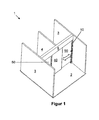
- FIG. 1 shows a sliding door system 1 according to a first embodiment of the invention.
- the system 1 here comprises two trained as a sliding door sash 50, which are exemplarily not visible here, above arranged fittings 51 suspended in a likewise not visible here, later explained in more detail drive profile 130 and taken guided along the marked by a block arrow directions. Both wings 50 are closed. Between the driving wings 50 an immovable fixed wing 40 is arranged. Ie. the driving wings 50 are moved when opening example behind the fixed wing 40.
- a transverse element 5 is arranged, which connects two side walls 3 of the sliding door system 1 with each other. It can be designed, for example, as a skylight.
- the drive profile 130 is attached to two externally arranged posts 10 set up on a floor 2, of which only the right one is visible. Furthermore, extending from the drive profile 130 and cross member 5 outgoing a separation or intermediate wall 4 in the direction of Be the sliding door system 1, which is formed by way of example by means of a framed fixed wing.
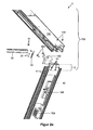
- FIG. 2a shows the sliding door system 1 in the region of attachment between an upper horizontal frame profile 30 of the intermediate wall 4 an outer post 10 and the now visible drive profile 130 of a drive part 100.
- the drive part 100 includes in the invention all parts that are necessary, one of the wings 50th to proceed.
- the frame profile 30 is screwed via a mounting bracket 32 by means of screws 33 with the outer post 10, namely its threaded openings 11, and thus securely fastened.
- the mounting bracket 30 is braced by means of screws 31 in the frame section 30.
- the outer post 10 here has a fastening section 12 on the upper side, likewise with threaded openings 11.
- screws 101 are screwed in, which were previously passed through a mounting bracket 102 of the drive member 100.
- the mounting bracket 102 like the mounting bracket 32 now clamped in the drive part 130 or, as here, by means of screws 103 are firmly screwed.
- the latter variant is used for secure fixation of the profiles 130, 10 to each other.
- non-visible outer post 10 creates a self-supporting frame that can be positioned and mounted as a whole, which simplifies the entire assembly.
- the outer post 10 there is a power supply unit 104 and a circuit 105, for example in the form of a sensor and / or control circuit for the other, recorded in the drive profile 130 linear drive.
- the drive profile 130 only has to accommodate the stator (s) (not illustrated here) from here by way of example two linear motors and optionally provide a guidance of the driving wings 50.
- the stator (s) may be distributed over the entire length of the drive profile 130 in accordance with desired drive forces, without regard to additional parts such as sensors or the like.
- FIG. 2b shows the sliding door system 1 in the field of attachment between intermediate sections 20, frame profiles 30 and drive profile 130.
- the frame profiles 30 are screwed by means of differently shaped fastening parts 32 and screws 33 in threaded openings 24 of a respective intermediate profile 20.
- the right frame profile 30 is attached to the outer post 10, whereas the left frame profile 30 is secured via a cross-sectionally approximately T-shaped fastening part 32 and screws 33 here at the middle intermediate post 20.
- This attachment part 32 has the basic shape of However, it additionally has a now third leg, which extends from the inserted into the frame section 30 legs substantially perpendicularly and away from the legs bolted to the intermediate post 20. About screws 35, this leg is screwed to a plate-like part 34. This part 34 in turn is inserted in a recess 106 formed as a mounting groove of the drive profile 130 and fixed, for example by means of screws.
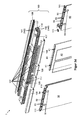
- FIG. 3a shows the front of the sliding door system 1 of FIG. 1 without walls 3, 4 and cross member 5.
- the door leaves 40, 50 are not sufficient for example to the floor 2 but are spaced therefrom.
- the drive part 100 comprises by way of example two drive profiles 130 arranged in a row, which, viewed in the direction of the bevel, are closed off at the front and rear sides by means of at least one respective side panel 108.
- the side panel 108 on the front side is not shown, so that cable guides 107 arranged by way of example can be seen by way of example.
- FIG. 3b shows the same arrangement from a different perspective.
- the aforementioned fittings 51 can be seen, with the aid of which the door leaves 50 are accommodated in the drive profile 130.
- Figure 3c shows a detail of the arrangement of FIG. 3b , only without door 50.
- the right and left suspension bracket 51 of the left and right door 50 are shown.
- At the upper end is followed by a later explained in more detail carriage 52, which is recorded guided in the drive profile 130.
- the fixed wing 40 which is otherwise not shown, is advantageously fastened to the drive profile 130 via a receiving profile 43.
- the receiving profile 43 opens on the upper side in two tab-like mounting bracket 41, which are screwed by screws 42 on the drive profile 130.
- the other fixed wing 40 is supported here from below in a corresponding receiving groove 44 of the receiving profile 43.
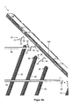
- FIG. 3d figure shows the arrangement of FIG. 3a in a partial exploded view.
- the here two suspension fittings 51 each door 50 open into each one of the aforementioned carriage 52.
- rollers 53 At its in or opposite to the direction of loading facing sides partially provided with reference numerals rollers 53 are arranged, the associated carriage 52 in a facing this, so here lower subspace 142 of a later explained in more detail receiving space 140 of the respective drive profile 130 along the travel path of the respective attached door leaf 50 lead.
- the carriages 52 are provided with a rotor part 54 on their side facing the drive profile 130, or they each form one.
- the rotor parts 54 each have a number of permanent magnets.
- the drive profile 130 is divided into two parts. Ie. the drive part 100 comprises two drive profiles 130, which abut each other on the front side and are arranged stationary relative to one another. The arrangement is such that the receiving spaces 140 of both profiles 130 are aligned with each other and thus form an entire receiving space 140.
- the rear subspace 142 of the right-hand drive profile 130 is at least partially covered in the direction of the door leaves 40, 50 by means of a cover panel 110.
- the left door 50 is received in here rear compartment 142 of the left drive profile 130.
- the front subspace 142 of the left drive profile 130 is also at least partially covered on the side facing the left door leaf 50 by means of a now second cover panel 110.
- the cover panels 110 are therefore arranged outside the travel paths of the door leaves 50.
- stoppers 111 are shown.
- the door leaves 50 are in the closed position and therefore abut or lie in the direction of the closed position on the left or right stopper 111.
- the other two stoppers 111 are arranged in relation to the respective nearest door leaf 50 in relation to this other subspace 142 of the drive profiles 130. Ie. they limit the movement of each received in the same subspace 142 door 50 in the opening direction and thus define its maximum opening width.
- the stoppers 111 are fastened in the respective subspace 142, for example by means of bracing.
- the stoppers 111 can be locked from the underside.
- the end positions of the door leaves 50 can be adjusted on site.
- the subspaces 142 or receiving spaces 140 of the drive profile 130 are separated from one another due to an intermediate wall 137 arranged therebetween and therefore run parallel to one another.
- the fastening profile 41 fastened or formed on the receiving profile 43 can be seen.
- the aforementioned cable guides 107 are attached to the outside of the respective drive profile 130 and serve the protected laying of energy and / or data lines, for example, to the aforementioned stators and possibly to other components such as sensors or the like.
- the drive profile 130 is provided with passage openings 117, which serve to pass lines from the direction of the cable guides 107 into a respective compartment 141, which forms the second part of the respective receiving space 140.
- a smoke detector may be used in the respective subspace 142 in the region of the respective cover panel 110.
- the cover panel 110 is interrupted in the detection range of the smoke detector or provided with holes.
- the drive profile arrangement formed in this way is optically closed at the front and at the rear, visually by means of the aforementioned side panels 108, viewed laterally or in the direction of loading.
- magnet rows formed here by means of respective permanent magnets are mounted as rotor parts 54 on the respective carriage 52. Further, the positions of the stoppers 111 with respect to the carriages 52 can be seen. From left, the first and third stoppers 111 are associated with the left carriage 52. All these elements are therefore arranged in the same, here rear receiving space 142 of the receiving profiles 130. Accordingly, the group right stator and, from left, second and fourth stopper 111 in the front receiving space 142 of the receiving profiles 130 is arranged.
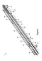
- FIG. 3e shows the arrangement of 3d figure diagonally from below.
- the stators are particularly easy to recognize.
- they essentially each consist of two stator modules 112 and a Hall sensor 118 arranged between them.
- Each stator module 112 is formed by way of example by means of a series of electric coils, which are connected in the usual way and optionally each provided with a magnetic magnetic return body.
- the stators are arranged one behind the other as seen in the direction of loading.
- the left stator is arranged in the rear receiving space 141 of the drive profile 130, whereas the right stator is arranged in the front receiving space 141 of the drive profile 130.
- the respective rotor (or carriage 52) is located below the associated stator. Ie. Each carriage 52 or attached to it, pointing in the direction of the stator permanent magnets are in energization of the associated stator with this in electromagnetic interaction, which can cause a movement of the carriage 52 and thus of the attached wing 50.
- the rollers 53 guide the associated carriage 52 in the respective receiving space 142 at least in the direction of the stator, to ensure the necessary minimum distance between stator and rotor.
- the stoppers 111 are also disposed in a respective one of the receiving spaces 142 and define the end positions of the associated carriage 52 and thus limit the travel of the associated wing 50.
- Activation sensors for example in the form of motion sensors, are shown here in an exemplary manner in front of and behind the left or right stator. These are therefore accommodated in the region of the respective receiving space 141 in which the stator is not arranged with taken.
- a controller 119 is arranged as the second component, which serves the operation of at least one of the stators and thus the linear motors.
- the drive profile 130 is preferably covered in the direction of carriage 52 by means of a cover panel 110 and thus protected against contamination, access, sabotage and the like.
- the cover panel 110 is transparent to the sensor or pierced in the sensor detection area. Ie. the sensor can "work through the cover panel 110".
- FIG. 3f It is in cross-section substantially U-shaped and open in the direction of wings 40, 50 and thus includes a non-descript cavity.
- right and left are on a crosspiece 136, the side legs 135 enclosing the U and these together connects, upper latching recesses 132 formed, engage in the corresponding latching projections 113 of a respective side panel 108.
- Lower detent recesses 132 are formed here like an undercut at the free end of each side leg 135.
- each successive projections 138 divide the respective receiving space 140 in the aforementioned upper and lower receiving space 141 and 142, respectively;
- Each receiving space 140 is divided into two.
- the here two receiving spaces 141 are used to hold stationary parts of the wing system 1, which may not be located in particular in the travel path of each suspended wing 50. This relates mainly to the respective tread 50 belonging stator 112 but also any additional elements such as the aforementioned sensors.
- projections 138 with their sides facing the transverse web 136, preferably serve as a support for the elements or components accommodated in the respectively associated receiving space 141.
- the carriages 52 of the here two driving wings 50 each have rollers 53 on both sides, which are displaced vertically relative to each other are arranged.
- the left rear and right front rollers 53 of the carriages 52 belong to one group, while the left front and right rear rollers 53 of the carriages 52 belong to the other group.
- the axes of rotation of the rollers 53 of the one group are shifted in relation to the rollers 53 of the other group in the direction of the transverse web 136.
- rollers 53 roll on in the direction of carriage 52 facing surfaces of the side legs 135 and the intermediate wall 137 centrally formed projections 138, while the rollers 53 of the other group on in the direction of these projections 138 facing surfaces of the free ends of the side legs 135th and the intermediate wall 137 unrolled projections 138 roll.
- the carriages 52 are thus held in a tilt-proof manner in the respective receiving space 142.
- the respective rotor part 54 is arranged on the transverse web 136 facing side of the carriage 52.
- the cable guides 107 indicated above have, viewed in cross-section, a respective receiving space 115 which is open at one location. Not shown cables or lines can be pressed through this point in ebenjenen receiving space 115 or else pushed along the front side into the receiving space 115 and thus securely laid.
- the drive profile 130 on its side legs 135 by way of example in cross-section C-shaped grooves 131, engage in the corresponding projections 120 of the respective cable guide 107 and thus securely fix the cable guide 107 on the drive profile 130.
- the receiving groove 131 preferably serves another purpose.
- the aforementioned plate-like parts 34 are designed to be inserted in the receiving groove 131 stationary.
- Below the grooves 131 are located on the outer sides of the side legs 135 by way of example additional grooves 139, in which, for example, the aforementioned plate-like parts 25 are used stationary.
- the components arranged here between the drive profile 130 and the wings 40, 50 are additionally accommodated in the drive profile 130.
- the cover panels 110 are arranged below the drive profile 130 and are preferably supported or attached to the surfaces of the lower projections 138 pointing in the direction of wings 40, 50.
- a stator module 112 is shown above the stoppers 111 and a component in the form of a controller 119 of the linear motor arranged on the right is shown on the left, which is accommodated in a stationary manner in the respective receiving space 141.
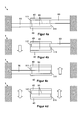
- FIG. 4 shows a sliding door system 1 according to a second embodiment of the invention from above and in various operating conditions. It is in turn designed as a double-leaf sliding door and inserted between two walls 3 and opposite sides of a door frame or the like. Ie. Stopper 111 can be dispensed with at these points as wing end positions. In Begehungscardi, here in the vertical direction, are located approximately in the center both in front of and behind the treads 50 two fixed wings 40. These preferably have the still outstanding stopper 111 on. These are integrally formed on the respective fixed wing 40 or attached. Because of the optics, the stoppers 111 preferably extend along the entire, associated fixed wing and thus additionally close it optically outward.
- a drive profile 130 which is designed as for the linear motors and the wing suspension as in the first embodiment of the invention.
- the block arrows indicate the respective direction of movement of the sliding door system 1.
- FIG. 4a shows the sliding door system 1 in the closed state.
- the dashed lines indicated end position of the tiller 50 represents their respective fully open position.
- an activation element not shown in detail, for example in the form of an opening switch, motion detector or the like.
- the activation element is advantageously arranged in the receiving space 140 of the drive profile 130. If the drive profile 130 with its two receiving spaces 140 extends over the entire width of the system, the activation element can be arranged, for example, of the right-hand wing 50 in the entire receiving space 140, in which the left-hand wing 50 is partially accommodated, in the area to the right Fixed wing 40, so outside the travel of the left wing 50th
- FIG. 4b shows a state after the left activating element is operated and then the associated, left driving wing 50 has been opened. In this state, the left door area can be passed down here. Thereafter, the left tiller 50 is closed again.
- Figure 4c shows the analog state for the right-hand drive wing 50. Thereafter, the right wing 50 is preferably also closed again, so that the in FIG. 4a shown position is reached again.
- FIG. 5 shows a sliding door system 1 according to a third embodiment of the invention also in different operating positions. It is designed as a double arch sliding door in the form of a lock.
- This sliding door system 1 is bordered by two walls 3 or the like in Begehungscardi exemplary.
- the driving wings 50 which are located diagonally opposite one another here, are moved synchronously with one another.
- an intermediate wall 4 which divides the passage created by the walls 3 in two part-passages.
- the intermediate wall 4 opens at its end facing a respective pair of vanes 50 in a portion corresponding to the function of one of the fixed wings 40 FIG. 4 takes over.
- the intermediate wall 4 has at said ends in each case via a stopper 111 which limits the movement of the respective closest of the two inner tails 50 in the opening direction and thus defines its fully open position.
- a Festerie140 is arranged, each of the function of the other of the fixed wing 40 according to FIG. 4 takes and also for the nearest tiller 50 has a stopper 111.
- FIG. 5a shows the sliding door system 1 in the closed state.
- FIG. 5b shows a state after one of these two activation elements has been actuated and then the left upper and the lower right traveling wings 50 have been opened. In this state, the passages released by these two vanes 50 can thus be passed here, left to the bottom or right to the top. Thereafter, both wings 50 are closed again.
- FIG. 5c the condition of Appendix 1 after completion of this process.
- the sliding door system 1 can be left.
- the upper right and left lower wings 50 are closed again, so that the in FIG. 5a shown position is reached again.
- this sliding door system 1 may be provided to completely release the passage, so all wings 50 to open completely. This condition is in FIG. 5d shown. In this latter case, in turn, an ascent in both directions is possible, again characterized by double block arrows.
- FIG. 6 shows a sliding door system 1 according to a fourth embodiment of the invention. It is essentially like the sliding door system 1 according to FIG. 5 designed. However, fixed wings 40 and stoppers 111 are missing here. In addition, the intermediate wall 4 lacks the end sections described above, which assume the function of a fixed wing 40 in each case.
- the intermediate wall 4 divides here also created by the walls 3 passage in two part-passages.
- the movement of the wings 80 is limited by the walls 3 and the stopper attached thereto, thus defining its fully open position. Therefore, separate stoppers 111 are not required.
- Figure 6a and Figure 6b show the sliding door system 1 each in the closed state, except that the respective top and bottom pairs of turrets 50 have exchanged their positions to each other.
- both pairs of wings 50 are formed and arranged so that they are in each end position, in the direction of Be, according to FIG. 6 So seen in the vertical direction, always close one of the partial passages and release the other.
- FIG. 6c shows a state after one of the activating elements of each upper left or lower right fl oor 50 has been operated, and then left upper and lower right fl oors 50 have been opened. Ie. depending on the closed position of the wings 50 according to FIG. 6a or FIG. 6b The outer and inner tails 50 are each moved so that the partial passages top left and bottom right is released. Therefore, in this state, the partial passages released by the vanes 50 can be passed again left to the bottom or right to the top.
- both tails 50 are closed again so that they also release the other part of each passage.
- FIG. 6d shows the condition of Appendix 1 after completion of this process.
- the sliding door system 1 can be left.
- each one of the upper and lower wings 50 is again moved so that one of the in Figure 6a and Figure 6b shown positions reached again.
- the drive profile 130 may also have more receiving spaces 140 instead of two. Instead of the side panels 108, the drive profile 130 itself may form the optical termination to the outside.
- the receiving spaces 140 of the drive profile 130 can each also accommodate a plurality of stators and so serve as the formation of a four-leaf sliding door system.
- the wings 50 can of course be moved according to other operating scenarios due to the respective own linear motor drive.
- the wings 50 according to FIG. 4 can be moved synchronously with each other or in dependence on each other.
- the wings 50 according to FIG. 5 and FIG. 6 can be moved individually independently of each other or in groups.
- each receiving space 140 stators of several driving wings 50 can be arranged.
- double telescopic sliding door systems can be realized.
- Each telescoping sliding door panel comprises, for example, two partial wings, which are accommodated in different receiving spaces 142 of the associated drive profile / s 130.
- the pairs of inner and outer part wings in the direction of access are in each case arranged in the same receiving space 142 of the drive profile / s 130. Under certain circumstances, two continuous receiving spaces 140 may also be sufficient in this case.
- the aforementioned embodiments can also be realized without a motor drive.
- the rotor parts 54 and stators are eliminated.
- the drive profiles 130 can be modified such that they only have the receiving spaces 142 as receiving spaces 140. This allows flatter and thus optically advantageous thus pure guide profiles. Furthermore, the advantage remains to be able to use in the guide profile, for example, sensors in areas that is not used by any of the wings 50 in.
- the invention provides a simply constructed, mounted and universally operable sliding door system.
- this sliding door system it is possible to control the flow of passers-by, which at least reduces the risk of collision.
Landscapes
- Engineering & Computer Science (AREA)
- Mechanical Engineering (AREA)
- Power-Operated Mechanisms For Wings (AREA)
- Wing Frames And Configurations (AREA)
Applications Claiming Priority (1)
| Application Number | Priority Date | Filing Date | Title |
|---|---|---|---|
| DE102011000132A DE102011000132A1 (de) | 2011-01-14 | 2011-01-14 | Schiebetürenanlage |
Publications (2)
| Publication Number | Publication Date |
|---|---|
| EP2476842A2 true EP2476842A2 (fr) | 2012-07-18 |
| EP2476842A3 EP2476842A3 (fr) | 2015-03-18 |
Family
ID=45218178
Family Applications (1)
| Application Number | Title | Priority Date | Filing Date |
|---|---|---|---|
| EP11009497.6A Withdrawn EP2476842A3 (fr) | 2011-01-14 | 2011-12-01 | Installation de portes coulissantes |
Country Status (2)
| Country | Link |
|---|---|
| EP (1) | EP2476842A3 (fr) |
| DE (1) | DE102011000132A1 (fr) |
Cited By (6)
| Publication number | Priority date | Publication date | Assignee | Title |
|---|---|---|---|---|
| EP3411551A4 (fr) * | 2016-02-01 | 2019-11-06 | Technologies Lanka Inc. | Actionneurs de porte, actionneur de porte intégré et procédé de fonctionnement d'un actionneur de porte d'un véhicule de transport |
| KR20200062279A (ko) * | 2017-10-26 | 2020-06-03 | 중산 오파이크 하드웨어 프로덕츠 컴퍼니 리미티드 | 슬라이딩 도어용 리니어 모터 |
| KR20200128380A (ko) * | 2018-02-02 | 2020-11-12 | 중산 오파이크 하드웨어 프로덕츠 컴퍼니 리미티드 | 신축 가능한 슬라이딩 도어용 리니어 모터 구조 |
| CN115443237A (zh) * | 2020-05-07 | 2022-12-06 | 克诺尔有限公司 | 用于驱动和引导用于轨道车辆的门的门开启模块、门扇、具有门扇和门开启模块的门系统和用于运行门系统的方法 |
| EP3702569B1 (fr) | 2017-10-26 | 2023-11-29 | Zhongshan Opike Hardware Product Co., Ltd | Système de moteur linéaire pour porte coulissante |
| EP4682338A1 (fr) | 2024-07-16 | 2026-01-21 | Hawa Sliding Solutions AG | Dispositif de moteur linéaire pour une installation de porte coulissante et installation de porte coulissante |
Families Citing this family (2)
| Publication number | Priority date | Publication date | Assignee | Title |
|---|---|---|---|---|
| AT521133B1 (de) | 2018-11-14 | 2019-11-15 | Blum Gmbh Julius | Führungssystem zur Führung eines bewegbar gelagerten Türflügels |
| DE102020112883A1 (de) | 2020-05-12 | 2021-11-18 | Dormakaba Deutschland Gmbh | Schiebetüranlage |
Family Cites Families (5)
| Publication number | Priority date | Publication date | Assignee | Title |
|---|---|---|---|---|
| EP1403459A2 (fr) * | 2002-09-27 | 2004-03-31 | Walter Meusburger | Paroi de séparation avec éléments coulissant horizontalement |
| DE102007032476A1 (de) * | 2007-07-10 | 2009-01-29 | Dorma Gmbh + Co. Kg | Mitnehmervorrichtung für eine Schiebetür |
| DE102007038840A1 (de) * | 2007-08-16 | 2009-02-19 | Dorma Gmbh + Co. Kg | Linearantrieb für Schiebetüren oder dergleichen |
| DE102007038847A1 (de) * | 2007-08-16 | 2009-02-19 | Dorma Gmbh + Co. Kg | Stator für einen Linearmotor |
| NZ583546A (en) * | 2007-08-29 | 2012-12-21 | Aneeta Window Systems Vic Pty Ltd | Sliding window or door with multiple panes and a sill and a head formed of parts snap-fitted together |
-
2011
- 2011-01-14 DE DE102011000132A patent/DE102011000132A1/de not_active Withdrawn
- 2011-12-01 EP EP11009497.6A patent/EP2476842A3/fr not_active Withdrawn
Non-Patent Citations (1)
| Title |
|---|
| None |
Cited By (12)
| Publication number | Priority date | Publication date | Assignee | Title |
|---|---|---|---|---|
| EP3411551A4 (fr) * | 2016-02-01 | 2019-11-06 | Technologies Lanka Inc. | Actionneurs de porte, actionneur de porte intégré et procédé de fonctionnement d'un actionneur de porte d'un véhicule de transport |
| US11001277B2 (en) | 2016-02-01 | 2021-05-11 | Technologies Lanka Inc. | Door actuators, integrated door actuator and method of operating a door actuator of a transit vehicle |
| KR20200062279A (ko) * | 2017-10-26 | 2020-06-03 | 중산 오파이크 하드웨어 프로덕츠 컴퍼니 리미티드 | 슬라이딩 도어용 리니어 모터 |
| EP3703230A4 (fr) * | 2017-10-26 | 2020-12-09 | Zhongshan Opike Hardware Product Co., Ltd | Moteur linéaire pour porte coulissante |
| US11486182B2 (en) | 2017-10-26 | 2022-11-01 | Zhongshan Opike Hardware Products Co., Ltd | Linear motor for sliding door |
| EP3702569B1 (fr) | 2017-10-26 | 2023-11-29 | Zhongshan Opike Hardware Product Co., Ltd | Système de moteur linéaire pour porte coulissante |
| KR20200128380A (ko) * | 2018-02-02 | 2020-11-12 | 중산 오파이크 하드웨어 프로덕츠 컴퍼니 리미티드 | 신축 가능한 슬라이딩 도어용 리니어 모터 구조 |
| EP3734006A4 (fr) * | 2018-02-02 | 2021-02-17 | Zhongshan Opike Hardware Products Co., Ltd | Structure de moteur linéaire extensible pour porte coulissante |
| US11591839B2 (en) * | 2018-02-02 | 2023-02-28 | Zhongshan Opike Hardware Products Co., Ltd | Telescopic linear motor structure for sliding door |
| CN115443237A (zh) * | 2020-05-07 | 2022-12-06 | 克诺尔有限公司 | 用于驱动和引导用于轨道车辆的门的门开启模块、门扇、具有门扇和门开启模块的门系统和用于运行门系统的方法 |
| EP4682338A1 (fr) | 2024-07-16 | 2026-01-21 | Hawa Sliding Solutions AG | Dispositif de moteur linéaire pour une installation de porte coulissante et installation de porte coulissante |
| WO2026017296A1 (fr) | 2024-07-16 | 2026-01-22 | Hawa Sliding Solutions Ag | Ensemble porte coulissante ayant un dispositif de moteur linéaire |
Also Published As
| Publication number | Publication date |
|---|---|
| DE102011000132A1 (de) | 2012-07-19 |
| EP2476842A3 (fr) | 2015-03-18 |
Similar Documents
| Publication | Publication Date | Title |
|---|---|---|
| EP2476842A2 (fr) | Installation de portes coulissantes | |
| EP2802500A1 (fr) | Système de porte de quai, procédé de fonctionnement d'un système de porte de quai et dormant pour un système de porte de quai | |
| EP2476849A2 (fr) | Profil de guidage pour une installation de porte coulissante automatique et installations de porte coulissante en étant équipées | |
| EP3670813B1 (fr) | Fenêtre ou porte dotée d'un bâti dormant et d'un battant coulissant | |
| WO2011076494A1 (fr) | Cabine d'ascenseur | |
| DE102008010671A1 (de) | Schwenktür für eine Personendurchgangsanlage | |
| DE102014119145A1 (de) | Schiebetor und Baukastensystem für ein Schiebetor | |
| EP1427907A1 (fr) | Element de battant de porte mobile et pivotant | |
| DE102005032168A1 (de) | Kreisschiebetüranordnung | |
| DE19900875C2 (de) | Verriegelungsvorrichtung für eine Türanlage | |
| EP3748114A1 (fr) | Système d'entraînement pour un battant pouvant être coulissé en tant que battant coulissant ou un battant levant-coulissant pouvant être coulissé d'une fenêtre ou d'une porte | |
| EP3957815B1 (fr) | Dispositif d'ombrage au-dessus des ouvertures d'angle de fenêtre ou de porte | |
| EP3101192A1 (fr) | Element de paroi de separation | |
| EP1743824A1 (fr) | Ensemble de porte coulissante pour perron et procédé pour son assemblage | |
| EP3441557B1 (fr) | Dispositif formant portail comportant un dispostif formant porte | |
| DE10001419B4 (de) | Türanlage | |
| EP2453097A2 (fr) | Dispositif de verrouillage pour une porte sectionnelle latérale | |
| EP2806090A2 (fr) | Dispositif pour le verrouillage ou le déverrouillage d'un ouvrant coulissant | |
| EP2679740A1 (fr) | Paroi de séparation mobile | |
| EP3816389B1 (fr) | Structure porteuse pour un agencement de porte coulissante de navire et agencement de porte coulissante de navire | |
| EP2878749B1 (fr) | Porte sectionnelle dotée d'un agencement de verrouillage | |
| EP2574716B1 (fr) | Porte ou fenêtre coulissante avec un dispositif d'aération et procédé de travail | |
| DE202024101220U1 (de) | Antriebsvorrichtung mit einer Führungsschiene für einen verschiebbaren Flügel als Schiebeflügel oder verschiebbaren Hebe-Schiebeflügel eines Fensters oder einer Tür | |
| DE4300333A1 (de) | Tor mit einem in die Schließ- und Offenstellung verschiebbaren Torblatt | |
| EP3216968B1 (fr) | Support central pour une ouverture de bâtiment ayant une grande largeur intérieure |
Legal Events
| Date | Code | Title | Description |
|---|---|---|---|
| PUAI | Public reference made under article 153(3) epc to a published international application that has entered the european phase |
Free format text: ORIGINAL CODE: 0009012 |
|
| AK | Designated contracting states |
Kind code of ref document: A2 Designated state(s): AL AT BE BG CH CY CZ DE DK EE ES FI FR GB GR HR HU IE IS IT LI LT LU LV MC MK MT NL NO PL PT RO RS SE SI SK SM TR |
|
| AX | Request for extension of the european patent |
Extension state: BA ME |
|
| PUAL | Search report despatched |
Free format text: ORIGINAL CODE: 0009013 |
|
| AK | Designated contracting states |
Kind code of ref document: A3 Designated state(s): AL AT BE BG CH CY CZ DE DK EE ES FI FR GB GR HR HU IE IS IT LI LT LU LV MC MK MT NL NO PL PT RO RS SE SI SK SM TR |
|
| AX | Request for extension of the european patent |
Extension state: BA ME |
|
| RAP1 | Party data changed (applicant data changed or rights of an application transferred) |
Owner name: DORMA DEUTSCHLAND GMBH |
|
| RIC1 | Information provided on ipc code assigned before grant |
Ipc: E05D 15/08 20060101ALI20150305BHEP Ipc: E05D 15/06 20060101AFI20150305BHEP |
|
| 17P | Request for examination filed |
Effective date: 20150918 |
|
| RBV | Designated contracting states (corrected) |
Designated state(s): AL AT BE BG CH CY CZ DE DK EE ES FI FR GB GR HR HU IE IS IT LI LT LU LV MC MK MT NL NO PL PT RO RS SE SI SK SM TR |
|
| STAA | Information on the status of an ep patent application or granted ep patent |
Free format text: STATUS: THE APPLICATION IS DEEMED TO BE WITHDRAWN |
|
| 18D | Application deemed to be withdrawn |
Effective date: 20150919 |