EP0956101B1 - Support de fixation d'une tete de pulverisation - Google Patents
Support de fixation d'une tete de pulverisation Download PDFInfo
- Publication number
- EP0956101B1 EP0956101B1 EP99900214A EP99900214A EP0956101B1 EP 0956101 B1 EP0956101 B1 EP 0956101B1 EP 99900214 A EP99900214 A EP 99900214A EP 99900214 A EP99900214 A EP 99900214A EP 0956101 B1 EP0956101 B1 EP 0956101B1
- Authority
- EP
- European Patent Office
- Prior art keywords
- spray head
- holder
- passage
- extinguishing medium
- displaced
- Prior art date
- Legal status (The legal status is an assumption and is not a legal conclusion. Google has not performed a legal analysis and makes no representation as to the accuracy of the status listed.)
- Expired - Lifetime
Links
- 239000007921 spray Substances 0.000 title claims abstract description 65
- 238000007789 sealing Methods 0.000 claims description 6
- XLYOFNOQVPJJNP-UHFFFAOYSA-N water Substances O XLYOFNOQVPJJNP-UHFFFAOYSA-N 0.000 description 12
- 230000000903 blocking effect Effects 0.000 description 4
- 239000003708 ampul Substances 0.000 description 2
- 238000010276 construction Methods 0.000 description 1
- 238000010168 coupling process Methods 0.000 description 1
- 238000005859 coupling reaction Methods 0.000 description 1
- 239000011521 glass Substances 0.000 description 1
- 230000005484 gravity Effects 0.000 description 1
- 238000005507 spraying Methods 0.000 description 1
Images


Classifications
-
- A—HUMAN NECESSITIES
- A62—LIFE-SAVING; FIRE-FIGHTING
- A62C—FIRE-FIGHTING
- A62C35/00—Permanently-installed equipment
- A62C35/58—Pipe-line systems
- A62C35/68—Details, e.g. of pipes or valve systems
Definitions
- the invention relates to a holder for mounting a spray head for fire fighting, comprising a body, a first end, a second end and a passage between the first and the second end for conducting extinguishing medium from the first end to the second end, a channel at the second end of the body for receiving the spray head in such a way that a housing of the spray head is inserted into the channel, the first end being intended to receive a conduit for supplying extinguishing medium.
- the holder can also be called a mounting part of a spray head.
- a holder of the above type is known from the publication WO 95/31252, for instance.
- the holder is typically mounted on a ceiling, but can be mounted on a wall, alternatively.
- SE 504 325 discloses a release device intended for a sprinkler head, facilitating function testing and comprising a remote-control pilot piston, which is, also in case of intact fuse, arranged to keep the passage between the inlet and the nozzle closed or open, respectively, depending on the position of the pilot piston.
- the present invention relates also to a combination of a holder and a spray head.
- Spray heads and sprinklers i.e. spray heads with built-in release means, are pressure tested or tested in another manner to secure their function in case of fire. After the tests, the sprinklers and/or spray heads are unscrewed from their respective holder to carry out possible adjustments and - if sprinklers are used - to replace the release means damaged at release, such as a broken glass ampoule, for instance.
- extinguishing medium remains in the conduit (for supplying extinguishing medium), though a section valve controlling the flow of extinguishing medium to the sprinklers or spray heads is closed.
- the extinguishing medium remained in the conduit conducting the extinguishing medium to the spray head flows out.
- the object of the invention is to solve said drawbacks.
- This object is achieved by means of a holder for mounting a spray head for fire fighting, comprising a body, a first end, a second end, and a passage between the first and the second end for conducting extinguishing medium from the first end to the second end, a channel at the second end of the body for receiving the spray head in such a way that a housing of the spray head is inserted into the channel, the first end being intended to receive a conduit for supplying extinguishing medium, and the holder comprising a displaceable element mounted in the passage, which element can be displaced from a first position, in which the element closes the passage, to a second position, in which the element keeps the passage open, wherein the element is arranged to be in the first position when the spray head is not mounted and to be displaced to the second position by the spray head when the spray head is being mounted to the holder.
- the combination of a holder and a spray head is characterized by the features set forth in the attached claim 10.
- the invention is essentially based on the idea to provide a construction in which a flow of water or other extinguishing medium out of the conduit leading to the spray head (or sprinkler) is automatically prevented upon the spray head or sprinkler being detached from its holder and in which the water flow is possible when the spray head (or sprinkler) is mounted to its holder.
- the invention relates to a valve of a holder for a spray head (or sprinkler) for fire fighting, the functional position of the valve being controlled depending on whether the spray head (or sprinkler) is mounted to the holder or not.
- the valve gets into a blocking position on account of the fact that 1) force of gravity acts on the valve, 2) pressure of extinguishing medium acts on the valve, or 3) an element, such as a spring, acts on the valve.
- the blocking position can also be provided as a result of a combination of said reasons.
- the greatest advantages of the invention are that it prevents extinguishing medium, e.g. water, from flowing out of conduits leading to sprinklers and spray heads, when sprinklers and spray heads are detached from their respective holders, and thus prevents considerable amounts of extinguishing medium from flowing out in places where the extinguishing medium may cause damage.
- extinguishing medium e.g. water
- Figure 1 shows a mounting part or a holder 1 for a spray head for fire fighting.
- the spray head can be mounted on a panel, for instance.
- the spray head may comprise an ampoule or another member, which is broken or which changes its shape at heat to make the spray head release, whereby the spray head together with said member forms a sprinkler.
- Such a sprinkler 2 is shown in Figure 2.
- the holder 1 is mounted on a panel 6 by means of screws 7 or corresponding fastening members.
- the panel 6 may typically constitute a ceiling.
- the holder can be mounted on a vertical surface or a slanting surface.
- a conduit 3 for supplying extinguishing medium mounted in the holder 1 is also drawn in Figure 1.
- the conduit 3 is kept mounted by means of a threaded part 4.
- the reference numeral 5 indicates a sealing.
- the holder 1 comprises a body 8, a first end 9 for receiving the conduit 3, and a second end 10 for receiving the sprinkler 2.
- a passage 11 for extinguishing medium leads from the first end 9 to the second end 10.
- the passage is blocked by a valve element 12, which is kept in the position shown in Figure 1 by its weight, i.e. by means of gravitation.
- a pressure in the conduit 3 can keep the valve element 12 sealingly in place by exposing a pressure surface 13d of the valve element to a force.
- An actuating surface 13e opposite to the pressure surface 13d, is formed at a lower end of the valve element 12. This actuating surface 13e works in cooperation with the sprinkler 2, for opening the passage 11, which will be described later.
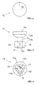
- FIGS 4, 5 and 6 show the valve element 12 from above, from the side and from below.
- the valve element 12 comprises a conically tapering portion 13a, which changes over to a guide portion 13b having a waist portion 13c and a wider portion with three projections 15, between which there are grooves 110, see Figures 5 and 6.
- the passage 11 (see Fig. 1) comprises a conically tapering seat 14a, whose shape corresponds to the conically tapering portion 13a of the valve element 12, and a cylindrical portion 14b for receiving the projections 15 of the guide portion.
- the conically tapering portion 13a constitutes together with the conically tapering seat 14a a sealing composed of a sealing surface or a sealing line blocking the passage 11.
- valve element 12 will be guided in the longitudinal direction of the passage 11.
- the cylindrical portion 14b of the passage 11 may be provided with shallow grooves 16 receiving the projections 15 of the valve element, in which case the valve element 12 can be kept steadily in place also when the passage 11 is open, cf. Fig. 3. This is the case also when the holder 1 is mounted in a horizontal position.
- a slot 40 is formed between the conically tapering portion 13a and the wall of the surrounding passage 11 even at the place where the diameter of the conically tapering portion is biggest.
- the grooves 110 of the guide portion 13b form channels for the flow of extinguishing medium past the slot 40 and the valve element 12 when this is in the open position, cf. Fig. 3 and 5.
- a flow of extinguishing medium past the slot 40 through the valve element 12 can also be provided (when the valve element is in the open position) by making the grooves 16 bigger than the projections 15 in such a way that the grooves 16 constitute passages for extinguishing medium.
- the shape of the guide portion 13b may vary in many ways: for instance, a waist portion is not absolutely necessary, though such a portion enables an efficient flow of extinguishing medium in spite of small size of the valve element 12. It is also conceivable that the end of the valve element 12 which faces the first end 9 of the holder is guided by the passage 11. Hereby, either the guide portion of the valve element or the passage is provided with grooves enabling a flow of extinguishing medium. In the latter case, the valve element 12 does not need any guide portion facing the second end 10 of the holder, but can have a guide portion at its end facing the first end 9 of the holder.
- the cross-sectional area of the cylindrical portion 14b constitutes about 3 to 30 % of the cross-sectional area of the passage 11.
- one or more channels are formed in the wall constituting the passage 11, which channels are opened by the valve element 12 being displaced to the position of Figure 3.
- Such a channel could replace the grooves 110 of the valve element 12 for the purpose of enabling a flow of extinguishing medium from the first end 9 of the holder to its second end 10.
- the lower end of the passage 11 is constituted by a channel 17 for receiving the sprinkler 2, see Fig. 1 and 2.
- the sprinkler 2 comprises a housing 18 with an upper end 19.
- the sprinkler 2 is screwed in place by means of threads 20 formed in the channel 17 of the holder 1.
- some other means e.g. bayonet connection or other quick-coupling means, can be used for fastening the sprinkler to the holder.
- the upper end 19 of the housing 18 presses against the actuating surface 13e and thus lifts the valve element 12 from the position shown in Figure 1 to the position shown in Figure 3.
- the passage 11 is opened and extinguishing medium may flow from the conduit 3 into the sprinkler 2.
- the expression actuating surface 13e signifies any type of actuating surface, which also can have a very small area.
- the actuating surface can be a point or a line (in Figure 9, the actuating surface is formed of a point).
- Figure 7 shows another embodiment of the holder 1' according to the invention.
- the holder 1' of Figure 7 differs from the holder of Figure 1 therein that it comprises, instead of a conically tapering valve element, a ball 12' loaded by a spring 30'.
- the ball 12' has a smaller diameter than the surrounding passage 11 so that there is a slot 40' between the ball and the wall of the surrounding channel.
- the spring 30' is a helical spring comprising a first end and a second end, the first end of the spring bearing against the ball 12' and the second end of the spring bearing against a ring element 40' in the passage 11'.
- the shape of the displaceable element 12, 12' may differ from an element having a conical portion or from a ball-shaped element.
- the element 12, 12' being mounted centrally in the passage 11, 11', it is conceivable that the element is built in the wall of the body 8, 8' of the holder. In the latter case, it is conceivable to a person skilled in the art that some other part of the housing 18, 18' of the sprinkler than the upper end 19, 19' of the sprinkler could attend to that the element will be displaced from the closing position to the opening position.
Landscapes
- Health & Medical Sciences (AREA)
- Public Health (AREA)
- Business, Economics & Management (AREA)
- Emergency Management (AREA)
- Fire-Extinguishing By Fire Departments, And Fire-Extinguishing Equipment And Control Thereof (AREA)
- Nozzles (AREA)
- Load-Engaging Elements For Cranes (AREA)
- Chain Conveyers (AREA)
- Catching Or Destruction (AREA)
- Details Or Accessories Of Spraying Plant Or Apparatus (AREA)
- Transition And Organic Metals Composition Catalysts For Addition Polymerization (AREA)
Claims (10)
- Support (1, 1') de montage d'une tête de pulvérisation (2, 2') de lutte contre l'incendie, comprenant un corps (8, 8'), une première extrémité (9, 9'), une seconde extrémité (10, 10') et un passage (11, 11') formé entre la première et la seconde extrémité et destiné à conduire un fluide d'extinction de la première extrémité à la seconde extrémité, un canal (17, 17') étant placé à la seconde extrémité du corps et destiné à loger la tête de pulvérisation de manière qu'un boítier (18, 18') de la tête de pulvérisation soit inséré dans le canal, la première extrémité étant destinée à loger un conduit de transmission du fluide d'extinction, caractérisé en ce que le support (1, 1') comporte un élément mobile (12, 12') monté dans le passage (11, 11'), cet élément pouvant être déplacé d'une première position dans laquelle l'élément ferme le passage à une seconde position dans laquelle l'élément maintient le passage ouvert, et l'élément (12, 12') est disposé afin qu'il occupe la première position lorsque la tête de pulvérisation (2, 2') n'est pas montée et soit déplacé à la seconde position par la tête de pulvérisation lorsque la tête de pulvérisation est montée sur le support.
- Support selon la revendication 1, dans lequel l'élément (12, 12') est destiné à être déplacé vers la seconde position par exposition de l'élément à une force par le boítier (18, 18') de la tête de pulvérisation, lorsque la tête de pulvérisation (2, 2') est en cours de montage sur le support (1, 1').
- Support selon la revendication 1, dans lequel l'élément (12) comporte une surface de pression (13d) destinée à être exposée à la pression du fluide d'extinction régnant dans le passage, la pression exposant l'élément à une force qui maintient l'élément dans la première position, lorsque la tête de pulvérisation (2) n'est pas montée.
- Support selon la revendication 1, dans lequel l'élément (12') est destiné à occuper la première position grâce à un ressort (30') qui expose l'élément à une force, lorsque la tête de pulvérisation (2') n'est pas montée.
- Support selon la revendication 1, dans lequel l'élément (12, 12') est destiné à occuper la première position sous l'action de la force de pesanteur, lorsque la tête de pulvérisation (2, 2') n'est pas montée.
- Support selon la revendication 1, dans lequel l'élément (12) comporte une partie effilée conique (13a) destinée à être en appui contre un siège tronconique (14a) placé dans le passage (11) du support, cette partie avec le siège constituant une surface d'étanchéité qui empêche l'écoulement du fluide d'extinction de la première extrémité (9) du support vers sa seconde extrémité (10), lorsque la tête de pulvérisation (2) n'est pas montée, cette partie étant destinée à être déplacée à distance du siège et à ouvrir une connexion entre la première extrémité et la seconde extrémité du support, lorsque la tête de pulvérisation est en cours de montage.
- Support selon la revendication 6, dans lequel l'élément (12) comporte des saillies radiales (15) s'étendant depuis une partie (13b) de l'élément, et le passage (11) comporte des gorges (16) destinées à loger les saillies de manière que celles-ci pénètrent dans les gorges.
- Support selon la revendication 6, dans lequel la partie effilée conique (13a) change de dimension vers le canal (17) et rejoint une partie de guidage (13b) qui comporte au moins un canal (110) maintenant ouvert le passage (11) entre la première extrémité (9) et la seconde extrémité (10) lorsque la tête de pulvérisation est montée.
- support selon la revendication 1, dans lequel l'élément comprend une bille (12') destinée à être en appui contre un siège (14a') disposé dans le corps (18') de la tête de pulvérisation, la bille et le siège constituant ensemble un dispositif d'étanchéité empêchant l'écoulement du fluide d'extinction de la première extrémité (9') du support vers sa seconde extrémité (10'), lorsque la tête de pulvérisation (2') n'est pas montée, la bille étant destinée à être déplacée à distance du siège et à ouvrir le passage (11) entre la première extrémité du support et sa seconde extrémité lorsque la tête de pulvérisation est en cours de montage.
- Combinaison d'un support (1, 1') et d'une tête de pulvérisation (2, 2'), le support étant destiné au montage d'une tête de pulvérisation de lutte contre l'incendie et comprenant un corps (8, 8'), une première extrémité (9, 9'), une seconde extrémité (10, 10') et un passage (11, 11') placé entre la première et la seconde extrémité et destiné à conduire un fluide d'extinction de la première extrémité à la seconde, un canal (17, 17') étant placé à la seconde extrémité du corps et destiné à loger la tête de pulvérisation de manière qu'un boítier (18, 18') de la tête de pulvérisation (2, 2') soit inséré dans le canal, la première extrémité étant destinée à loger un conduit de transmission d'un fluide d'extinction, caractérisée en ce que le support (1, 1') comporte un élément mobile (12, 12') monté dans le passage (11, 11'), cet élément pouvant être déplacé d'une première position dans laquelle l'élément ferme le passage à une seconde position dans laquelle l'élément maintient le passage ouvert, dans lequel l'élément (12, 12') est destiné à occuper la première position lorsque la tête de pulvérisation (2, 2') n'est pas montée, et à être déplacé vers la seconde position par la tête de pulvérisation lorsque la tête de pulvérisation est en cours de montage sur le support.
Priority Applications (1)
| Application Number | Priority Date | Filing Date | Title |
|---|---|---|---|
| DE29923523U DE29923523U1 (de) | 1998-01-09 | 1999-01-07 | Halter für Sprinkler oder Sprühköpfe |
Applications Claiming Priority (3)
| Application Number | Priority Date | Filing Date | Title |
|---|---|---|---|
| FI980034 | 1998-01-09 | ||
| FI980034A FI103480B1 (fi) | 1998-01-09 | 1998-01-09 | Pidin suihkutuspään asentamiseksi |
| PCT/FI1999/000007 WO1999034872A1 (fr) | 1998-01-09 | 1999-01-07 | Support de fixation d'une tete de pulverisation |
Publications (2)
| Publication Number | Publication Date |
|---|---|
| EP0956101A1 EP0956101A1 (fr) | 1999-11-17 |
| EP0956101B1 true EP0956101B1 (fr) | 2000-11-02 |
Family
ID=8550317
Family Applications (1)
| Application Number | Title | Priority Date | Filing Date |
|---|---|---|---|
| EP99900214A Expired - Lifetime EP0956101B1 (fr) | 1998-01-09 | 1999-01-07 | Support de fixation d'une tete de pulverisation |
Country Status (18)
| Country | Link |
|---|---|
| US (1) | US6536534B1 (fr) |
| EP (1) | EP0956101B1 (fr) |
| JP (1) | JP2001515391A (fr) |
| KR (1) | KR100583855B1 (fr) |
| CN (1) | CN1150045C (fr) |
| AT (1) | ATE197253T1 (fr) |
| AU (1) | AU754007B2 (fr) |
| CA (1) | CA2283421C (fr) |
| DE (1) | DE69900016T2 (fr) |
| DK (2) | DK0956101T3 (fr) |
| ES (1) | ES2151321T3 (fr) |
| FI (1) | FI103480B1 (fr) |
| GR (1) | GR3035247T3 (fr) |
| MY (1) | MY130759A (fr) |
| NO (1) | NO327108B1 (fr) |
| RU (1) | RU2216370C2 (fr) |
| TW (1) | TW474829B (fr) |
| WO (1) | WO1999034872A1 (fr) |
Families Citing this family (22)
| Publication number | Priority date | Publication date | Assignee | Title |
|---|---|---|---|---|
| FI112038B (fi) | 2000-05-16 | 2003-10-31 | Marioff Corp Oy | Asennusvälineet suihkutuspään asentamiseksi seinämään |
| US7143834B2 (en) * | 2001-11-01 | 2006-12-05 | Kevin Michael Dolan | Sprinkler assembly |
| US7269878B2 (en) * | 2003-12-11 | 2007-09-18 | Euro Pro Operatin Llc | Steam stop for steam cleaner |
| US7293721B2 (en) * | 2004-10-26 | 2007-11-13 | James C Roberts | Check valve assembly for sprinkler head |
| US7686235B2 (en) * | 2004-10-26 | 2010-03-30 | Roberts James C | Check valve assembly for controlling the flow of pressurized fluids |
| JP2008531882A (ja) * | 2005-02-23 | 2008-08-14 | ドナルド・ジー・ヒューバー | 一体式給水遮断バルブを備えた蛇口アセンブリ |
| JP2007267765A (ja) * | 2006-03-30 | 2007-10-18 | Nohmi Bosai Ltd | スプリンクラヘッドの立ち下げ配管 |
| FI118458B (fi) * | 2006-06-12 | 2007-11-30 | Marioff Corp Oy | Menetelmä ja laitteisto suihkutuspään yhteydessä sekä suihkutuspään suojaelin |
| US7878419B2 (en) * | 2006-09-19 | 2011-02-01 | Sta-Rite Industries, Llc | Spray head with covers |
| US20100326677A1 (en) * | 2008-01-04 | 2010-12-30 | Jepsen Jens T | Water mist head for a fire fighting system |
| DK177453B1 (en) * | 2010-06-15 | 2013-06-17 | Danfoss Semco As | Spray head for a uniform fluid distribution |
| SE535545C2 (sv) * | 2010-07-28 | 2012-09-18 | Ultra Fog Ab | Sprinklerhuvud |
| JP2012085749A (ja) * | 2010-10-18 | 2012-05-10 | Ohbayashi Corp | スプリンクラーヘッド用の止水機能付着脱継手、及び消火用のスプリンクラー設備 |
| CN104168963B (zh) | 2012-03-05 | 2019-04-12 | 马里奥夫有限公司 | 水雾灭火喷洒器 |
| WO2018125804A1 (fr) | 2016-12-28 | 2018-07-05 | Tyco Fire Products Lp | Ensembles de gicleurs d'incendie et installations dotées de raccords instantanés réglables |
| US11242673B2 (en) | 2017-01-18 | 2022-02-08 | Aquor Water Systems, Incorporated | Anti-freezing water valve with optional anti-siphon assembly and water-valve accessories |
| US11186970B2 (en) | 2017-03-29 | 2021-11-30 | Aquor Water Systems, Incorporated | Anti-freezing water valve configured for underground (buried) use and with optional anti-siphon assembly, and water-valve accessories |
| WO2018183758A1 (fr) * | 2017-03-29 | 2018-10-04 | Aquor Water Systems, Incorporated | Tête d'extincteur d'incendie amovible comprenant une soupape d'admission d'eau |
| US11045675B2 (en) * | 2018-02-02 | 2021-06-29 | Victaulic Company | Belleville seal for valve seat having a tear drop laminar flow feature |
| CA3162713A1 (fr) * | 2019-11-25 | 2021-06-03 | Sprinkler Stop, Llc | Soupape en ligne pour remplacement de tete d'arroseur |
| CN112618993A (zh) * | 2021-01-26 | 2021-04-09 | 陕西安益消防科技有限公司 | 分布式车辆喷淋灭火装置 |
| RU206841U1 (ru) * | 2021-06-24 | 2021-09-29 | Общество С Ограниченной Ответственностью "Фогстрим" | Ороситель системы пожаротушения |
Family Cites Families (29)
| Publication number | Priority date | Publication date | Assignee | Title |
|---|---|---|---|---|
| US1432386A (en) * | 1922-10-17 | Alfred s | ||
| US629304A (en) * | 1898-12-19 | 1899-07-18 | George Rawlins | Faucet or tap. |
| US951519A (en) * | 1909-05-25 | 1910-03-08 | Natalin Bacigalupi | Sprinkling apparatus. |
| US1268160A (en) * | 1917-02-21 | 1918-06-04 | Thomas A Sammons | Automatic cut-off valve and faucet mechanism. |
| GB198945A (en) * | 1922-08-30 | 1923-06-14 | Alfred Steven Curney | Improvements in and relating to fire-extinguishing sprinkler heads |
| US1740015A (en) * | 1927-05-18 | 1929-12-17 | Snap Valve Corp | Sprinkler valve |
| US3750954A (en) * | 1972-04-27 | 1973-08-07 | L Williams | Sprinkler system and adapter valve therefor |
| US4220208A (en) * | 1977-11-21 | 1980-09-02 | Hays Heating & Plumbing Company | Dry pipe fire extinguishing sprinkler system |
| CH624014A5 (fr) * | 1977-12-23 | 1981-07-15 | Johann Georg Mohler | |
| US4562962A (en) * | 1983-05-20 | 1986-01-07 | Hartman Woody W | Sprinkling system and valve therefor |
| SU1764662A1 (ru) * | 1987-08-31 | 1992-09-30 | Центральное Проектно-Конструкторское Бюро По Разработке Приборов И Аппаратуры Систем Автоматического Пожаротушения, Пожарной И Охранной Сигнализации "Спецавтоматика" | Спринклер |
| WO1991000240A1 (fr) * | 1989-06-29 | 1991-01-10 | Helmut Skerra | Unite de soupape |
| US4944327A (en) * | 1989-10-04 | 1990-07-31 | Gyben Christopher J | Riser check valve |
| CH681249A5 (fr) * | 1990-07-04 | 1993-02-15 | Helmut Ensmenger | |
| US5184683A (en) * | 1991-03-06 | 1993-02-09 | Hattori Takamasa | Sprinkler head |
| US5174500A (en) * | 1991-03-28 | 1992-12-29 | Yianilos Nicholas P | Fail safe lawn sprinkler device |
| DE4122665A1 (de) * | 1991-07-09 | 1993-01-14 | Total Feuerschutz Gmbh | Sprinkler fuer selbsttaetige feuerloeschanlagen |
| JPH06467U (ja) * | 1991-12-26 | 1994-01-11 | ホーチキ株式会社 | スプリンクラー巻出し配管ユニット |
| US5441203A (en) * | 1993-01-25 | 1995-08-15 | Lurmark Limited | Spray nozzle holder containing two valves for flow control |
| US5335857A (en) * | 1993-07-14 | 1994-08-09 | Sprinkler Sentry, Inc. | Sprinkler breakage, flooding and theft prevention mechanism |
| US5324265A (en) | 1993-10-20 | 1994-06-28 | Gabbard Murray Gabbard Inc. | Hypodermic safety syringe with retracting needle system |
| DE4426730C2 (de) | 1994-07-28 | 2002-09-26 | Ehrensperger C Ag | Ventileinsatz für unter Druck stehende Fluidbehälter |
| US5533576A (en) | 1994-08-01 | 1996-07-09 | Grinnell Corporation | Automatic on-off fire protection sprinkler |
| US5485982A (en) | 1994-09-16 | 1996-01-23 | Bundy Corporation | Quick connector with tube activated check valve |
| US5524824A (en) * | 1994-10-06 | 1996-06-11 | Frimmer; Elliot M. | Sprinkler shut-off valve and indicator |
| JPH08141082A (ja) | 1994-11-22 | 1996-06-04 | Atsushi Hirota | 注射器 |
| SE504325C2 (sv) * | 1995-03-16 | 1997-01-13 | Kure Fastighets & Foervaltning | Utlösningsanordning för sprinklerhuvud |
| US5577706A (en) * | 1995-10-25 | 1996-11-26 | King; Robert J. | Water faucet with automatic shut-off mechanism for water conservation |
| US6024175A (en) * | 1998-04-17 | 2000-02-15 | Moore, Jr.; Fred D. | Automatic sealing sprinkler head adapter and fire protection sprinkler system |
-
1998
- 1998-01-09 FI FI980034A patent/FI103480B1/fi not_active IP Right Cessation
-
1999
- 1999-01-06 TW TW088100152A patent/TW474829B/zh not_active IP Right Cessation
- 1999-01-07 WO PCT/FI1999/000007 patent/WO1999034872A1/fr not_active Ceased
- 1999-01-07 EP EP99900214A patent/EP0956101B1/fr not_active Expired - Lifetime
- 1999-01-07 AT AT99900214T patent/ATE197253T1/de not_active IP Right Cessation
- 1999-01-07 DK DK99900214T patent/DK0956101T3/da active
- 1999-01-07 AU AU18803/99A patent/AU754007B2/en not_active Ceased
- 1999-01-07 CA CA002283421A patent/CA2283421C/fr not_active Expired - Fee Related
- 1999-01-07 DE DE69900016T patent/DE69900016T2/de not_active Expired - Lifetime
- 1999-01-07 KR KR1019997008185A patent/KR100583855B1/ko not_active Expired - Lifetime
- 1999-01-07 JP JP53572099A patent/JP2001515391A/ja active Pending
- 1999-01-07 US US09/367,972 patent/US6536534B1/en not_active Expired - Lifetime
- 1999-01-07 RU RU99121325/12A patent/RU2216370C2/ru active
- 1999-01-07 CN CNB998000272A patent/CN1150045C/zh not_active Expired - Lifetime
- 1999-01-07 ES ES99900214T patent/ES2151321T3/es not_active Expired - Lifetime
- 1999-01-08 MY MYPI99000071A patent/MY130759A/en unknown
- 1999-09-08 NO NO19994350A patent/NO327108B1/no not_active IP Right Cessation
-
2000
- 2000-07-27 DK DK200000239U patent/DK200000239U3/da not_active IP Right Cessation
-
2001
- 2001-01-17 GR GR20010400067T patent/GR3035247T3/el unknown
Also Published As
| Publication number | Publication date |
|---|---|
| MY130759A (en) | 2007-07-31 |
| FI980034A0 (fi) | 1998-01-09 |
| NO327108B1 (no) | 2009-04-27 |
| NO994350D0 (no) | 1999-09-08 |
| US6536534B1 (en) | 2003-03-25 |
| EP0956101A1 (fr) | 1999-11-17 |
| CN1255872A (zh) | 2000-06-07 |
| FI103480B (sv) | 1999-07-15 |
| DE69900016D1 (de) | 2000-12-07 |
| DE69900016T2 (de) | 2001-03-15 |
| JP2001515391A (ja) | 2001-09-18 |
| NO994350L (no) | 1999-09-08 |
| DK200000239U3 (da) | 2000-09-08 |
| CA2283421A1 (fr) | 1999-07-15 |
| TW474829B (en) | 2002-02-01 |
| WO1999034872A1 (fr) | 1999-07-15 |
| DK0956101T3 (da) | 2000-11-27 |
| FI103480B1 (fi) | 1999-07-15 |
| ES2151321T3 (es) | 2000-12-16 |
| KR100583855B1 (ko) | 2006-05-26 |
| CN1150045C (zh) | 2004-05-19 |
| AU1880399A (en) | 1999-07-26 |
| RU2216370C2 (ru) | 2003-11-20 |
| AU754007B2 (en) | 2002-10-31 |
| ATE197253T1 (de) | 2000-11-15 |
| KR20000076097A (ko) | 2000-12-26 |
| CA2283421C (fr) | 2007-03-27 |
| GR3035247T3 (en) | 2001-04-30 |
Similar Documents
| Publication | Publication Date | Title |
|---|---|---|
| EP0956101B1 (fr) | Support de fixation d'une tete de pulverisation | |
| CA2199803C (fr) | Crepine d'incendie | |
| EP0665761B1 (fr) | Tete pulverisatrice destinee a etre utilisee pour lutter contre les incendies | |
| US4417626A (en) | Adjustable pendent sprinkler assembly | |
| KR20080069585A (ko) | 유체 충전 및/또는 추출 제어 장치와 이러한 장치를포함하는 탱크 | |
| EP0991448B1 (fr) | Pulverisateur ou tete de pulverisation | |
| CA2449036A1 (fr) | Asperseur | |
| GB2156213A (en) | An automatically and manually operable portable fire extinguisher | |
| JP2001340485A (ja) | 差圧式開放弁および開放式スプリンクラー設備 | |
| US20190308046A1 (en) | Main valve with pressure relief valve having a lockout feature | |
| DK2512607T3 (en) | FIRE-FIGHTING DEVICE FOR TRANSFORMING A LIQUID TO A LIQUID MIST | |
| KR101058570B1 (ko) | 소방용 관창 | |
| FI109879B (sv) | Installering för brandbekämpning | |
| KR102064669B1 (ko) | 소방차량 충수 시스템 | |
| AU726182C (en) | Sprinkler or spray head | |
| AU692546B2 (en) | Sprinkler | |
| AU685672C (en) | Sprinkler | |
| US271669A (en) | Automatic fire-extinguisher | |
| SU1500323A1 (ru) | Запорно-пусковое устройство автоматической установки пожаротушени | |
| FI100947B (fi) | Tulensammutuslaite, suuttimen ja suihkutuspään yhdistelmäsuutin ja men etelmä tulen sammuttamiseksi | |
| JPS59203573A (ja) | 消火方式 |
Legal Events
| Date | Code | Title | Description |
|---|---|---|---|
| PUAI | Public reference made under article 153(3) epc to a published international application that has entered the european phase |
Free format text: ORIGINAL CODE: 0009012 |
|
| 17P | Request for examination filed |
Effective date: 19990910 |
|
| AK | Designated contracting states |
Kind code of ref document: A1 Designated state(s): AT BE CH CY DE DK ES FI FR GB GR IE IT LI LU MC NL PT SE |
|
| 17Q | First examination report despatched |
Effective date: 19991227 |
|
| GRAG | Despatch of communication of intention to grant |
Free format text: ORIGINAL CODE: EPIDOS AGRA |
|
| GRAG | Despatch of communication of intention to grant |
Free format text: ORIGINAL CODE: EPIDOS AGRA |
|
| GRAH | Despatch of communication of intention to grant a patent |
Free format text: ORIGINAL CODE: EPIDOS IGRA |
|
| GRAG | Despatch of communication of intention to grant |
Free format text: ORIGINAL CODE: EPIDOS AGRA |
|
| GRAH | Despatch of communication of intention to grant a patent |
Free format text: ORIGINAL CODE: EPIDOS IGRA |
|
| GRAA | (expected) grant |
Free format text: ORIGINAL CODE: 0009210 |
|
| AK | Designated contracting states |
Kind code of ref document: B1 Designated state(s): AT BE CH CY DE DK ES FI FR GB GR IE IT LI LU MC NL PT SE |
|
| PG25 | Lapsed in a contracting state [announced via postgrant information from national office to epo] |
Ref country code: LI Free format text: LAPSE BECAUSE OF FAILURE TO SUBMIT A TRANSLATION OF THE DESCRIPTION OR TO PAY THE FEE WITHIN THE PRESCRIBED TIME-LIMIT Effective date: 20001102 Ref country code: FI Free format text: LAPSE BECAUSE OF FAILURE TO SUBMIT A TRANSLATION OF THE DESCRIPTION OR TO PAY THE FEE WITHIN THE PRESCRIBED TIME-LIMIT Effective date: 20001102 Ref country code: CY Free format text: LAPSE BECAUSE OF NON-PAYMENT OF DUE FEES Effective date: 20001102 Ref country code: CH Free format text: LAPSE BECAUSE OF FAILURE TO SUBMIT A TRANSLATION OF THE DESCRIPTION OR TO PAY THE FEE WITHIN THE PRESCRIBED TIME-LIMIT Effective date: 20001102 Ref country code: AT Free format text: LAPSE BECAUSE OF FAILURE TO SUBMIT A TRANSLATION OF THE DESCRIPTION OR TO PAY THE FEE WITHIN THE PRESCRIBED TIME-LIMIT Effective date: 20001102 |
|
| REF | Corresponds to: |
Ref document number: 197253 Country of ref document: AT Date of ref document: 20001115 Kind code of ref document: T |
|
| REG | Reference to a national code |
Ref country code: CH Ref legal event code: EP |
|
| REG | Reference to a national code |
Ref country code: DK Ref legal event code: T3 |
|
| REF | Corresponds to: |
Ref document number: 69900016 Country of ref document: DE Date of ref document: 20001207 |
|
| REG | Reference to a national code |
Ref country code: IE Ref legal event code: FG4D |
|
| REG | Reference to a national code |
Ref country code: ES Ref legal event code: FG2A Ref document number: 2151321 Country of ref document: ES Kind code of ref document: T3 |
|
| PG25 | Lapsed in a contracting state [announced via postgrant information from national office to epo] |
Ref country code: LU Free format text: LAPSE BECAUSE OF NON-PAYMENT OF DUE FEES Effective date: 20010107 |
|
| PG25 | Lapsed in a contracting state [announced via postgrant information from national office to epo] |
Ref country code: IE Free format text: LAPSE BECAUSE OF NON-PAYMENT OF DUE FEES Effective date: 20010108 |
|
| ITF | It: translation for a ep patent filed | ||
| ET | Fr: translation filed | ||
| PG25 | Lapsed in a contracting state [announced via postgrant information from national office to epo] |
Ref country code: MC Free format text: LAPSE BECAUSE OF NON-PAYMENT OF DUE FEES Effective date: 20010131 |
|
| PG25 | Lapsed in a contracting state [announced via postgrant information from national office to epo] |
Ref country code: PT Free format text: LAPSE BECAUSE OF FAILURE TO SUBMIT A TRANSLATION OF THE DESCRIPTION OR TO PAY THE FEE WITHIN THE PRESCRIBED TIME-LIMIT Effective date: 20010202 |
|
| REG | Reference to a national code |
Ref country code: CH Ref legal event code: PL |
|
| PLBE | No opposition filed within time limit |
Free format text: ORIGINAL CODE: 0009261 |
|
| STAA | Information on the status of an ep patent application or granted ep patent |
Free format text: STATUS: NO OPPOSITION FILED WITHIN TIME LIMIT |
|
| 26N | No opposition filed | ||
| REG | Reference to a national code |
Ref country code: IE Ref legal event code: MM4A |
|
| NLS | Nl: assignments of ep-patents |
Owner name: MARIOFF CORPORATION OY |
|
| REG | Reference to a national code |
Ref country code: GB Ref legal event code: IF02 |
|
| REG | Reference to a national code |
Ref country code: GB Ref legal event code: 732E |
|
| REG | Reference to a national code |
Ref country code: FR Ref legal event code: TP |
|
| PGFP | Annual fee paid to national office [announced via postgrant information from national office to epo] |
Ref country code: BE Payment date: 20120117 Year of fee payment: 14 Ref country code: DK Payment date: 20120111 Year of fee payment: 14 Ref country code: SE Payment date: 20120112 Year of fee payment: 14 |
|
| BERE | Be: lapsed |
Owner name: *MARIOFF CORP. OY Effective date: 20130131 |
|
| REG | Reference to a national code |
Ref country code: DK Ref legal event code: EBP |
|
| REG | Reference to a national code |
Ref country code: SE Ref legal event code: EUG |
|
| PG25 | Lapsed in a contracting state [announced via postgrant information from national office to epo] |
Ref country code: SE Free format text: LAPSE BECAUSE OF NON-PAYMENT OF DUE FEES Effective date: 20130108 Ref country code: BE Free format text: LAPSE BECAUSE OF NON-PAYMENT OF DUE FEES Effective date: 20130131 |
|
| PG25 | Lapsed in a contracting state [announced via postgrant information from national office to epo] |
Ref country code: DK Free format text: LAPSE BECAUSE OF NON-PAYMENT OF DUE FEES Effective date: 20130131 |
|
| REG | Reference to a national code |
Ref country code: FR Ref legal event code: PLFP Year of fee payment: 18 |
|
| REG | Reference to a national code |
Ref country code: FR Ref legal event code: PLFP Year of fee payment: 19 |
|
| REG | Reference to a national code |
Ref country code: FR Ref legal event code: PLFP Year of fee payment: 20 |
|
| PGFP | Annual fee paid to national office [announced via postgrant information from national office to epo] |
Ref country code: FR Payment date: 20171221 Year of fee payment: 20 Ref country code: NL Payment date: 20171222 Year of fee payment: 20 |
|
| PGFP | Annual fee paid to national office [announced via postgrant information from national office to epo] |
Ref country code: GR Payment date: 20171221 Year of fee payment: 20 Ref country code: GB Payment date: 20171222 Year of fee payment: 20 |
|
| PGFP | Annual fee paid to national office [announced via postgrant information from national office to epo] |
Ref country code: DE Payment date: 20171218 Year of fee payment: 20 Ref country code: ES Payment date: 20180201 Year of fee payment: 20 |
|
| PGFP | Annual fee paid to national office [announced via postgrant information from national office to epo] |
Ref country code: IT Payment date: 20180102 Year of fee payment: 20 |
|
| REG | Reference to a national code |
Ref country code: DE Ref legal event code: R071 Ref document number: 69900016 Country of ref document: DE |
|
| REG | Reference to a national code |
Ref country code: NL Ref legal event code: MK Effective date: 20190106 |
|
| REG | Reference to a national code |
Ref country code: GB Ref legal event code: PE20 Expiry date: 20190106 |
|
| PG25 | Lapsed in a contracting state [announced via postgrant information from national office to epo] |
Ref country code: GB Free format text: LAPSE BECAUSE OF EXPIRATION OF PROTECTION Effective date: 20190106 |
|
| REG | Reference to a national code |
Ref country code: ES Ref legal event code: FD2A Effective date: 20200904 |
|
| PG25 | Lapsed in a contracting state [announced via postgrant information from national office to epo] |
Ref country code: ES Free format text: LAPSE BECAUSE OF EXPIRATION OF PROTECTION Effective date: 20190108 |