EP0957561A2 - Rotorblechpaket für drehende elektrische Maschinen - Google Patents
Rotorblechpaket für drehende elektrische Maschinen Download PDFInfo
- Publication number
- EP0957561A2 EP0957561A2 EP99302825A EP99302825A EP0957561A2 EP 0957561 A2 EP0957561 A2 EP 0957561A2 EP 99302825 A EP99302825 A EP 99302825A EP 99302825 A EP99302825 A EP 99302825A EP 0957561 A2 EP0957561 A2 EP 0957561A2
- Authority
- EP
- European Patent Office
- Prior art keywords
- lamination
- laminations
- rotor core
- shaft
- formation
- Prior art date
- Legal status (The legal status is an assumption and is not a legal conclusion. Google has not performed a legal analysis and makes no representation as to the accuracy of the status listed.)
- Withdrawn
Links
Images


Classifications
-
- H—ELECTRICITY
- H02—GENERATION; CONVERSION OR DISTRIBUTION OF ELECTRIC POWER
- H02K—DYNAMO-ELECTRIC MACHINES
- H02K1/00—Details of the magnetic circuit
- H02K1/06—Details of the magnetic circuit characterised by the shape, form or construction
- H02K1/22—Rotating parts of the magnetic circuit
- H02K1/28—Means for mounting or fastening rotating magnetic parts on to, or to, the rotor structures
Definitions
- the present invention is concerned with rotor cores for electrical rotating machines.
- the term electrical rotating machine is intended to cover any form of apparatus having a rotating member which generates, converts, transforms or modifies electric power; inter alia such machines will comprise motors, generators, synchronous condensers, synchronous converters, rotating amplifiers, phase modifiers and combinations of these in any one machine.
- Such a machine normally incorporates at least one rotor rotatable with a rotatable shaft, and the rotor usually comprises a metal core on which electrical conductors in one form or another are mounted; inter alia the core may be formed with slots for wound coils or for bars.
- the rotor core of an electrical rotating machine from a stack of laminations pressed together and shrunk onto a rotatable shaft.
- the laminations are typically formed from sheets of electrical grade steel with the laminations having an appropriate insulating substance e.g. a varnish, resin or other appropriate (organic or inorganic) compound applied thereto.
- an appropriate insulating substance e.g. a varnish, resin or other appropriate (organic or inorganic) compound applied thereto.
- the laminations are typically placed on a mandrel, pressed together at a suitably high pressure (say 200 psi) and then heated up and shrunk directly onto a pre-machined shaft.
- the shape of the shaft rotor assembly may vary in service as the core pressure relaxes over time.
- the aim of the invention is to provide a rotor core wherein, during assembly of the laminations on the shaft and subsequently in service, movement is possible between adjacent laminations or more particularly between adjacent stacks of laminations so that the core pack can conform to the natural shape of the shaft.
- a method of assembling a rotor core onto a rotatable shaft of a rotating electrical machine, said rotor core comprising a plurality of laminations which method includes the step of providing at least one side of at least one of said laminations with a formation which has a coefficient of friction such that said at least one lamination and a lamination adjacent thereto are able to slide relatively to one another when the laminations are mounted on the shaft.
- a method of assembling a rotor core of a rotating electrical machine onto a rotatable shaft, said rotor core comprising a plurality of laminations which method includes the step of providing at least one side of at least one of the laminations with a formation which allows the at least one lamination and a lamination which is adjacent thereto to slide relatively to one another when the laminations are mounted on the shaft.
- the formation is preferably provided on a plurality of first said laminations and when the laminations are assembled on the shaft, each of those first laminations are spaced from the nearest first lamination or laminations by one or more second said laminations on which the formation is not provided.
- Each said first lamination may be spaced from the closest first lamination or laminations by a distance constituting a percentage of the diameter of the shaft the percentage may be in the range 30-90% of the diameter of the shaft, and preferably the percentage is of the order of 60% of the diameter of the shaft.
- Said step of providing a formation may comprise the application of a material, e.g. by spraying, to the surface of the said side of the one lamination or laminations, or may comprise the application of at least one sheet of material to the one lamination or laminations.
- the material preferably comprises a low-friction material, such as fully or partially halogenated hydrocarbon, e.g. polytetrafluoroethylene, or at least a material having a lower coefficient of friction than the insulating substances normally applied to the laminations before assembly on a mandrel.
- a low-friction material such as fully or partially halogenated hydrocarbon, e.g. polytetrafluoroethylene, or at least a material having a lower coefficient of friction than the insulating substances normally applied to the laminations before assembly on a mandrel.
- the method may further include the steps of holding all the laminations of the core in juxtaposition, pressing them, heating and then shrinking them onto the shaft.
- the invention provides a rotor core for an electrical rotating machine said rotor core comprising a plurality of laminations at least one of which has on at least one side thereof a formation, which formation allows the at least one lamination and a lamination which is adjacent thereto to slide relatively to one another.
- the invention provides a rotor core for an electrical rotating machine said rotor core comprising a plurality of laminations at least one of which has on at least one side thereof a formation which has a coefficient of friction such that said at least one lamination and a lamination which is adjacent thereto are able to slide relative to one another.
- the formation may be provided on a plurality of first laminations each of which is spaced from the nearest first lamination by one or more second laminations on which the formation is not provided and each said first lamination may be spaced from the closest first lamination or laminations by a distance constituting a percentage of the diameter of the shaft, e.g. in the range 30-90% of the diameter of the shaft. Preferably the percentage is of the order of 60% of the diameter of the shaft.
- the formation may be provided by a material comprising a fully or partially halogenated hydrocarbon e.g. polytetrafluoroethylene.
- the invention provides a lamination for a rotor core of an electrical machine said lamination having a formation on at least one side thereof which allows the lamination and a lamination which is adjacent thereto, in use, to slide relatively to one another.
- the invention provides a lamination for a rotor core of an electrical machine which lamination has on at least one side thereof a formation which has a coefficient of friction such that said lamination and a lamination which is adjacent thereto, in use, are able to slide relative to one another.
- the formation may be provided by a material applied, e.g. by spraying, to the lamination, or may be in the form of at least one sheet of material applied to the at least one side; the material may comprise a fully or partially halogenated hydrocarbon, e.g. polytetrafluoroethylene.
- the invention can substantially reduce the vibration of a rotor core, in use.
- the invention is applicable to any shape or form of laminations which can be utilised to form a rotor core.
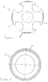
- a lamination 10 with four salient poles 11 such a lamination is generally referred to as cruciform and typically is utilised in forming a pack for use in a synchronous machine e.g. a motor or generator, conductor coils being wound around the arms of the cruciform.
- a synchronous machine e.g. a motor or generator, conductor coils being wound around the arms of the cruciform.
- Figure 2 a ring-formed lamination 20 which typically is utilised in forming a pack for use in the rotor of an induction machine, specifically a squirrel-cage induction motor.
- the outer circumference of the lamination 20 is formed with slots 21 for receiving the rotor bars.
- Figure 5 illustrates the production of a core pack C.
- Laminations 30 of any convenient form e.g. as illustrated in Figure 1 or 2 are mounted on a central axially extending mandrel (not shown) and are pressed together and held under pressure between clamp plates 41, 42 having axially extending members, e.g. studs or bolts 51, 52, 53 therebetween which are utilised (as by the tightening of associated nuts 54-59) to move the clamp plates 41, 42 relatively towards one another.
- axially extending members e.g. studs or bolts 51, 52, 53
- Each axially extending member 51-53 may be provided outside the circumferences of the laminations or may extend (with a suitable clearance) through apertures in the laminations - in the latter case such member may become an integral part of the core pack C when such is mounted on a shaft.
- one or more of the laminations 30 is provided on at least one side thereof with a formation which allows the lamination and a lamination adjacent thereto to slide relatively to one another when the laminations are mounted on a shaft: the formation has a coefficient of friction such that this relative sliding can occur during both assembly and use of the rotor core C to allow the core pack to conform to the shape of the shaft.
- the rotor core C thus formed is heated and shrunk onto the shaft 60 (see Figure 6).
- the aforesaid formation is in the form of a sheet or sheets of low-friction material of a suitable shape formed separately from the lamination and placed between adjacent laminations.
- a suitable shape formed separately from the lamination and placed between adjacent laminations.
- Such shape need only approximate the shape of the lamination or indeed may extend over only a limited area or areas of the face of the lamination.
- each pole 11 may have a separate piece of material 12 or a 'patch' applied thereto or associated therewith.
- each such patch is of generally rectangular shape but other shapes are possible.
- the sheet 22 may have a simple annular shape, without the necessity of having equivalent slots in the sheet.
- the sheet will have an outer circumference with a diameter less than the diameter of the inner parts of slots 21 and an inner circumference with a diameter greater than the diameter of the inner circumference of the lamination.
- the sheet may be formed of a fully or partially halogenated hydrocarbon e.g. a fluorocarbon particularly PTFE.
- the formation may be formed by applying a low-friction material such as a fully or partially halogenated hydrocarbon e.g. a fluorocarbon, particularly PTFE, directly to an area or areas of the lamination, e.g. by spraying.
- a low-friction material such as a fully or partially halogenated hydrocarbon e.g. a fluorocarbon, particularly PTFE, directly to an area or areas of the lamination, e.g. by spraying.
- each core section 31, 38 has an axial extent corresponding to a percentage of the diameter of the shaft 60, such percentage is preferably in the range 30-90% of the diameter of the shaft and more especially of the order of 60%.
- each of those laminations provided with the material abuts against respective adjacent laminations along a slip plane S wherein sliding or slipping movement between them is possible, effectively allowing movement between sections of the rotor core C in a plane extending in directions D substantially normal to the longitudinal axis 61 of the shaft 60. It is to be understood that the amount of such movement will generally not exceed more than a few microns and indeed may be less than 1 micron.
- the core pack will conform to the natural (machined) shape of the shaft. Should the shaft have been bent as the core pack is assembled thereon the movement along the slip plane(s) will allow the shaft to return to its machined state. In this regard it is envisaged that by rotating the shaft above its normal maximum speed, which will normally be done as a proving check, the slipping movement will then more readily occur to allow the shaft to return to its normal shape.
- vibration of the rotor core C in use can be substantially reduced.
Landscapes
- Engineering & Computer Science (AREA)
- Power Engineering (AREA)
- Iron Core Of Rotating Electric Machines (AREA)
- Manufacture Of Motors, Generators (AREA)
Applications Claiming Priority (2)
| Application Number | Priority Date | Filing Date | Title |
|---|---|---|---|
| GB9807691 | 1998-04-14 | ||
| GB9807691A GB2338115B (en) | 1998-04-14 | 1998-04-14 | Improvements in or relating to rotor cores for electrical rotating machines |
Publications (2)
| Publication Number | Publication Date |
|---|---|
| EP0957561A2 true EP0957561A2 (de) | 1999-11-17 |
| EP0957561A3 EP0957561A3 (de) | 2000-12-20 |
Family
ID=10830157
Family Applications (1)
| Application Number | Title | Priority Date | Filing Date |
|---|---|---|---|
| EP99302825A Withdrawn EP0957561A3 (de) | 1998-04-14 | 1999-04-12 | Rotorblechpaket für drehende elektrische Maschinen |
Country Status (2)
| Country | Link |
|---|---|
| EP (1) | EP0957561A3 (de) |
| GB (1) | GB2338115B (de) |
Cited By (4)
| Publication number | Priority date | Publication date | Assignee | Title |
|---|---|---|---|---|
| CN105308836A (zh) * | 2013-06-20 | 2016-02-03 | 株式会社神户制钢所 | 发电机 |
| IT201800010873A1 (it) * | 2018-12-06 | 2020-06-06 | Magneti Marelli Spa | Metodo di inserimento di un albero in un nucleo magnetico di un rotore di una macchina elettrica rotante |
| EP4203278A1 (de) * | 2021-12-23 | 2023-06-28 | Valeo eAutomotive Germany GmbH | Rotormontageverfahren |
| EP4203279A1 (de) * | 2021-12-23 | 2023-06-28 | Valeo eAutomotive Germany GmbH | Rotormontageverfahren |
Family Cites Families (12)
| Publication number | Priority date | Publication date | Assignee | Title |
|---|---|---|---|---|
| CH598682A5 (de) * | 1976-06-16 | 1978-05-12 | Bbc Brown Boveri & Cie | |
| JPS56112839A (en) * | 1980-02-08 | 1981-09-05 | Takashi Namiki | Thin steel plate for rotor core of motor |
| JPS60216744A (ja) * | 1984-04-12 | 1985-10-30 | Toshiba Corp | 積層鉄心の製造方法 |
| JPS6216033A (ja) * | 1985-07-10 | 1987-01-24 | Hitachi Ltd | 小形モ−タのア−マチユア |
| DE3720217A1 (de) * | 1987-06-17 | 1988-12-29 | Metallgesellschaft Ag | Verfahren zur erzeugung elektrisch isolierender ueberzuege auf metalloberflaechen |
| JPH0236784A (ja) * | 1988-07-26 | 1990-02-06 | Stanley Electric Co Ltd | モータ駆動装置 |
| JPH02159944A (ja) * | 1988-12-08 | 1990-06-20 | Matsushita Electric Ind Co Ltd | 回転電気の回転子 |
| US5023500A (en) * | 1989-04-21 | 1991-06-11 | Century Electric, Inc. | Stator lamination with alignment structure for controlled skewing |
| JPH03285530A (ja) * | 1990-03-30 | 1991-12-16 | Matsushita Electric Ind Co Ltd | 誘導電動機のロータ |
| JPH04190669A (ja) * | 1990-11-21 | 1992-07-09 | Matsushita Electric Ind Co Ltd | 誘導電動機のロータ構造 |
| JPH05103448A (ja) * | 1991-10-04 | 1993-04-23 | Asmo Co Ltd | 回転電機のコアの製造方法 |
| JPH09294347A (ja) * | 1996-04-25 | 1997-11-11 | Tokyo Parts Ind Co Ltd | 回転電機用積層コア |
-
1998
- 1998-04-14 GB GB9807691A patent/GB2338115B/en not_active Expired - Fee Related
-
1999
- 1999-04-12 EP EP99302825A patent/EP0957561A3/de not_active Withdrawn
Cited By (9)
| Publication number | Priority date | Publication date | Assignee | Title |
|---|---|---|---|---|
| CN105308836A (zh) * | 2013-06-20 | 2016-02-03 | 株式会社神户制钢所 | 发电机 |
| EP3012948A4 (de) * | 2013-06-20 | 2017-02-22 | Kabushiki Kaisha Kobe Seiko Sho (Kobe Steel, Ltd.) | Generator |
| CN105308836B (zh) * | 2013-06-20 | 2018-01-23 | 株式会社神户制钢所 | 发电机 |
| US10063114B2 (en) | 2013-06-20 | 2018-08-28 | Kobe Steel, Ltd. | Generator |
| IT201800010873A1 (it) * | 2018-12-06 | 2020-06-06 | Magneti Marelli Spa | Metodo di inserimento di un albero in un nucleo magnetico di un rotore di una macchina elettrica rotante |
| EP4203278A1 (de) * | 2021-12-23 | 2023-06-28 | Valeo eAutomotive Germany GmbH | Rotormontageverfahren |
| EP4203279A1 (de) * | 2021-12-23 | 2023-06-28 | Valeo eAutomotive Germany GmbH | Rotormontageverfahren |
| WO2023118431A1 (en) * | 2021-12-23 | 2023-06-29 | Valeo Eautomotive Germany Gmbh | A rotor assembly method |
| WO2023118465A1 (en) * | 2021-12-23 | 2023-06-29 | Valeo Eautomotive Germany Gmbh | A rotor assembly method |
Also Published As
| Publication number | Publication date |
|---|---|
| GB2338115A (en) | 1999-12-08 |
| GB2338115B (en) | 2002-08-07 |
| EP0957561A3 (de) | 2000-12-20 |
| GB9807691D0 (en) | 1998-06-10 |
Similar Documents
| Publication | Publication Date | Title |
|---|---|---|
| JP3735197B2 (ja) | コイル成形体の製造方法およびそれに用いる金型 | |
| US10158262B2 (en) | Stator for electric rotating machine | |
| US7605505B2 (en) | Rotating electric machine rotor pole crossover | |
| US20070222323A1 (en) | Stator of a rotary electric machine having secured core slot insulators | |
| US20140306573A1 (en) | Stator for electric rotating machine and method of manufacturing the same | |
| US6956307B2 (en) | Soft magnetic composite powder metal cores | |
| EP0881747A3 (de) | Wechselstromgenerator für Kraftfahrzeuge | |
| JPWO2020054233A1 (ja) | 回転電機の固定子および該固定子を具備する回転電機 | |
| KR102654000B1 (ko) | 고정자를 구비하는 회전 전기 기계 | |
| CA1225113A (en) | Slot armor for dynamoelectric machines | |
| CA1138021A (en) | Laminated pole for an electrical machine with well-defined poles | |
| DE60225211T2 (de) | Elektrische Generator-Anlasservorrichtung für Kraftfahrzeuge | |
| US4146809A (en) | Sleeve for a rotor of a dynamoelectric machine | |
| US20030048032A1 (en) | Wound stator core and method of making | |
| EP0957561A2 (de) | Rotorblechpaket für drehende elektrische Maschinen | |
| US12218546B2 (en) | Stator and manufacturing method of the stator | |
| EP2595159A2 (de) | Wickeldraht für elektrische Maschine | |
| JPH0213540B2 (de) | ||
| US20080179985A1 (en) | Rotating electrical machine | |
| JP3879649B2 (ja) | 固定子の分解方法及び固定子の分解装置 | |
| JP4066834B2 (ja) | 回転電機の巻線の製造方法 | |
| GB2452135A (en) | Capped stator core wedge and related method | |
| CA2965307A1 (en) | Lamination pack for producing stators and/or rotors of electric motors and generators | |
| US7872384B2 (en) | Shaft cover structure for use in an exciter | |
| RU2127016C1 (ru) | Способ изготовления асинхронного электродвигателя и асинхронный электродвигатель с короткозамкнутым ротором |
Legal Events
| Date | Code | Title | Description |
|---|---|---|---|
| PUAI | Public reference made under article 153(3) epc to a published international application that has entered the european phase |
Free format text: ORIGINAL CODE: 0009012 |
|
| AK | Designated contracting states |
Kind code of ref document: A2 Designated state(s): CH DE FR GB IT LI SE |
|
| AX | Request for extension of the european patent |
Free format text: AL;LT;LV;MK;RO;SI |
|
| K1C3 | Correction of patent application (complete document) published |
Effective date: 19991117 |
|
| PUAL | Search report despatched |
Free format text: ORIGINAL CODE: 0009013 |
|
| AK | Designated contracting states |
Kind code of ref document: A3 Designated state(s): AT BE CH CY DE DK ES FI FR GB GR IE IT LI LU MC NL PT SE |
|
| AX | Request for extension of the european patent |
Free format text: AL;LT;LV;MK;RO;SI |
|
| RIC1 | Information provided on ipc code assigned before grant |
Free format text: 7H 02K 1/28 A, 7H 02K 15/02 B |
|
| 17P | Request for examination filed |
Effective date: 20010430 |
|
| AKX | Designation fees paid |
Free format text: CH DE FR GB IT LI SE |
|
| 17Q | First examination report despatched |
Effective date: 20050218 |
|
| RAP1 | Party data changed (applicant data changed or rights of an application transferred) |
Owner name: ALSTOM POWER CONVERSION LTD |
|
| RAP1 | Party data changed (applicant data changed or rights of an application transferred) |
Owner name: CONVERTEAM LTD |
|
| STAA | Information on the status of an ep patent application or granted ep patent |
Free format text: STATUS: THE APPLICATION IS DEEMED TO BE WITHDRAWN |
|
| 18D | Application deemed to be withdrawn |
Effective date: 20060919 |