EP0965652B1 - Alliages absorbant l'hydrogene, procedes de production de ces alliages, electrode realisee a l'aide de cet alliage et procede de fabrication et accumulateur - Google Patents
Alliages absorbant l'hydrogene, procedes de production de ces alliages, electrode realisee a l'aide de cet alliage et procede de fabrication et accumulateur Download PDFInfo
- Publication number
- EP0965652B1 EP0965652B1 EP98961578A EP98961578A EP0965652B1 EP 0965652 B1 EP0965652 B1 EP 0965652B1 EP 98961578 A EP98961578 A EP 98961578A EP 98961578 A EP98961578 A EP 98961578A EP 0965652 B1 EP0965652 B1 EP 0965652B1
- Authority
- EP
- European Patent Office
- Prior art keywords
- hydrogen storage
- storage alloy
- phase
- formula
- battery
- Prior art date
- Legal status (The legal status is an assumption and is not a legal conclusion. Google has not performed a legal analysis and makes no representation as to the accuracy of the status listed.)
- Expired - Lifetime
Links
- 239000001257 hydrogen Substances 0.000 title claims description 306
- 229910052739 hydrogen Inorganic materials 0.000 title claims description 306
- UFHFLCQGNIYNRP-UHFFFAOYSA-N Hydrogen Chemical compound [H][H] UFHFLCQGNIYNRP-UHFFFAOYSA-N 0.000 title claims description 293
- 229910045601 alloy Inorganic materials 0.000 title claims description 237
- 239000000956 alloy Substances 0.000 title claims description 237
- 238000000034 method Methods 0.000 title claims description 46
- 238000003860 storage Methods 0.000 claims description 267
- 239000000203 mixture Substances 0.000 claims description 63
- 229910000905 alloy phase Inorganic materials 0.000 claims description 40
- 239000000843 powder Substances 0.000 claims description 39
- 229910052751 metal Inorganic materials 0.000 claims description 18
- 239000002184 metal Substances 0.000 claims description 18
- 239000013078 crystal Substances 0.000 claims description 17
- 239000000463 material Substances 0.000 claims description 17
- 239000011230 binding agent Substances 0.000 claims description 14
- 238000005245 sintering Methods 0.000 claims description 9
- 230000001747 exhibiting effect Effects 0.000 claims description 7
- 229910020632 Co Mn Inorganic materials 0.000 claims description 6
- 238000001816 cooling Methods 0.000 claims description 6
- 229910020678 Co—Mn Inorganic materials 0.000 claims description 5
- 238000003411 electrode reaction Methods 0.000 claims description 4
- 229910003310 Ni-Al Inorganic materials 0.000 claims 1
- PXHVJJICTQNCMI-UHFFFAOYSA-N nickel Substances [Ni] PXHVJJICTQNCMI-UHFFFAOYSA-N 0.000 description 63
- 239000011572 manganese Substances 0.000 description 52
- 125000004429 atom Chemical group 0.000 description 36
- 230000007423 decrease Effects 0.000 description 24
- 239000002585 base Substances 0.000 description 23
- 239000002245 particle Substances 0.000 description 19
- 239000010949 copper Substances 0.000 description 18
- 229910052759 nickel Inorganic materials 0.000 description 16
- 229910001122 Mischmetal Inorganic materials 0.000 description 15
- 239000000654 additive Substances 0.000 description 10
- 238000010438 heat treatment Methods 0.000 description 9
- 238000006243 chemical reaction Methods 0.000 description 8
- 150000002431 hydrogen Chemical class 0.000 description 8
- 238000005984 hydrogenation reaction Methods 0.000 description 8
- 239000002002 slurry Substances 0.000 description 8
- 229910052782 aluminium Inorganic materials 0.000 description 7
- 230000000694 effects Effects 0.000 description 6
- 229910052748 manganese Inorganic materials 0.000 description 6
- 238000002441 X-ray diffraction Methods 0.000 description 5
- 229910052802 copper Inorganic materials 0.000 description 5
- 230000000996 additive effect Effects 0.000 description 4
- 238000005275 alloying Methods 0.000 description 4
- 125000004435 hydrogen atom Chemical group [H]* 0.000 description 4
- 238000002844 melting Methods 0.000 description 4
- 230000008018 melting Effects 0.000 description 4
- 239000011148 porous material Substances 0.000 description 4
- 238000007712 rapid solidification Methods 0.000 description 4
- 238000003466 welding Methods 0.000 description 4
- 229920002134 Carboxymethyl cellulose Polymers 0.000 description 3
- 230000004913 activation Effects 0.000 description 3
- 229910052796 boron Inorganic materials 0.000 description 3
- 235000010948 carboxy methyl cellulose Nutrition 0.000 description 3
- 230000008602 contraction Effects 0.000 description 3
- 239000006185 dispersion Substances 0.000 description 3
- 229910052746 lanthanum Inorganic materials 0.000 description 3
- 238000002156 mixing Methods 0.000 description 3
- 229910052721 tungsten Inorganic materials 0.000 description 3
- XKRFYHLGVUSROY-UHFFFAOYSA-N Argon Chemical compound [Ar] XKRFYHLGVUSROY-UHFFFAOYSA-N 0.000 description 2
- 229910004269 CaCu5 Inorganic materials 0.000 description 2
- 229910052684 Cerium Inorganic materials 0.000 description 2
- LFQSCWFLJHTTHZ-UHFFFAOYSA-N Ethanol Chemical compound CCO LFQSCWFLJHTTHZ-UHFFFAOYSA-N 0.000 description 2
- 229910018561 MmNi5 Inorganic materials 0.000 description 2
- 239000001768 carboxy methyl cellulose Substances 0.000 description 2
- 239000008112 carboxymethyl-cellulose Substances 0.000 description 2
- 239000003054 catalyst Substances 0.000 description 2
- 230000003197 catalytic effect Effects 0.000 description 2
- 238000006555 catalytic reaction Methods 0.000 description 2
- 229910017052 cobalt Inorganic materials 0.000 description 2
- 239000010941 cobalt Substances 0.000 description 2
- GUTLYIVDDKVIGB-UHFFFAOYSA-N cobalt atom Chemical compound [Co] GUTLYIVDDKVIGB-UHFFFAOYSA-N 0.000 description 2
- 238000007796 conventional method Methods 0.000 description 2
- 230000003247 decreasing effect Effects 0.000 description 2
- 239000004570 mortar (masonry) Substances 0.000 description 2
- 230000001737 promoting effect Effects 0.000 description 2
- 238000010791 quenching Methods 0.000 description 2
- 229910052761 rare earth metal Inorganic materials 0.000 description 2
- 238000007711 solidification Methods 0.000 description 2
- 230000008023 solidification Effects 0.000 description 2
- 239000002904 solvent Substances 0.000 description 2
- 239000000126 substance Substances 0.000 description 2
- WFKWXMTUELFFGS-UHFFFAOYSA-N tungsten Chemical compound [W] WFKWXMTUELFFGS-UHFFFAOYSA-N 0.000 description 2
- 239000010937 tungsten Substances 0.000 description 2
- XLYOFNOQVPJJNP-UHFFFAOYSA-N water Substances O XLYOFNOQVPJJNP-UHFFFAOYSA-N 0.000 description 2
- 229910052726 zirconium Inorganic materials 0.000 description 2
- 229910004247 CaCu Inorganic materials 0.000 description 1
- VYZAMTAEIAYCRO-UHFFFAOYSA-N Chromium Chemical compound [Cr] VYZAMTAEIAYCRO-UHFFFAOYSA-N 0.000 description 1
- RYGMFSIKBFXOCR-UHFFFAOYSA-N Copper Chemical compound [Cu] RYGMFSIKBFXOCR-UHFFFAOYSA-N 0.000 description 1
- 229910018007 MmNi Inorganic materials 0.000 description 1
- 229910018657 Mn—Al Inorganic materials 0.000 description 1
- 229910052779 Neodymium Inorganic materials 0.000 description 1
- 229910000990 Ni alloy Inorganic materials 0.000 description 1
- 239000004743 Polypropylene Substances 0.000 description 1
- 229910052777 Praseodymium Inorganic materials 0.000 description 1
- QCWXUUIWCKQGHC-UHFFFAOYSA-N Zirconium Chemical compound [Zr] QCWXUUIWCKQGHC-UHFFFAOYSA-N 0.000 description 1
- 239000003513 alkali Substances 0.000 description 1
- XAGFODPZIPBFFR-UHFFFAOYSA-N aluminium Chemical compound [Al] XAGFODPZIPBFFR-UHFFFAOYSA-N 0.000 description 1
- 238000004458 analytical method Methods 0.000 description 1
- 239000007864 aqueous solution Substances 0.000 description 1
- 229910052786 argon Inorganic materials 0.000 description 1
- 230000033228 biological regulation Effects 0.000 description 1
- 229910052729 chemical element Inorganic materials 0.000 description 1
- 210000000991 chicken egg Anatomy 0.000 description 1
- 229910052804 chromium Inorganic materials 0.000 description 1
- 239000011651 chromium Substances 0.000 description 1
- 239000011248 coating agent Substances 0.000 description 1
- 238000000576 coating method Methods 0.000 description 1
- 238000002485 combustion reaction Methods 0.000 description 1
- 230000000052 comparative effect Effects 0.000 description 1
- 238000010586 diagram Methods 0.000 description 1
- 230000005611 electricity Effects 0.000 description 1
- 239000003792 electrolyte Substances 0.000 description 1
- 238000004453 electron probe microanalysis Methods 0.000 description 1
- 239000007789 gas Substances 0.000 description 1
- 229910000765 intermetallic Inorganic materials 0.000 description 1
- 229910052742 iron Inorganic materials 0.000 description 1
- XEEYBQQBJWHFJM-UHFFFAOYSA-N iron Substances [Fe] XEEYBQQBJWHFJM-UHFFFAOYSA-N 0.000 description 1
- FZLIPJUXYLNCLC-UHFFFAOYSA-N lanthanum atom Chemical compound [La] FZLIPJUXYLNCLC-UHFFFAOYSA-N 0.000 description 1
- WPBNNNQJVZRUHP-UHFFFAOYSA-L manganese(2+);methyl n-[[2-(methoxycarbonylcarbamothioylamino)phenyl]carbamothioyl]carbamate;n-[2-(sulfidocarbothioylamino)ethyl]carbamodithioate Chemical compound [Mn+2].[S-]C(=S)NCCNC([S-])=S.COC(=O)NC(=S)NC1=CC=CC=C1NC(=S)NC(=O)OC WPBNNNQJVZRUHP-UHFFFAOYSA-L 0.000 description 1
- 238000005259 measurement Methods 0.000 description 1
- 229910052750 molybdenum Inorganic materials 0.000 description 1
- 239000004745 nonwoven fabric Substances 0.000 description 1
- 230000008520 organization Effects 0.000 description 1
- -1 polypropylene Polymers 0.000 description 1
- 229920001155 polypropylene Polymers 0.000 description 1
- 239000002244 precipitate Substances 0.000 description 1
- 238000003825 pressing Methods 0.000 description 1
- 230000000171 quenching effect Effects 0.000 description 1
- 150000002910 rare earth metals Chemical group 0.000 description 1
- 238000007670 refining Methods 0.000 description 1
- 229920006395 saturated elastomer Polymers 0.000 description 1
- 239000000243 solution Substances 0.000 description 1
- 125000006850 spacer group Chemical group 0.000 description 1
- 229910052719 titanium Inorganic materials 0.000 description 1
Images



Classifications
-
- B—PERFORMING OPERATIONS; TRANSPORTING
- B22—CASTING; POWDER METALLURGY
- B22F—WORKING METALLIC POWDER; MANUFACTURE OF ARTICLES FROM METALLIC POWDER; MAKING METALLIC POWDER; APPARATUS OR DEVICES SPECIALLY ADAPTED FOR METALLIC POWDER
- B22F9/00—Making metallic powder or suspensions thereof
- B22F9/02—Making metallic powder or suspensions thereof using physical processes
- B22F9/023—Hydrogen absorption
-
- H—ELECTRICITY
- H01—ELECTRIC ELEMENTS
- H01M—PROCESSES OR MEANS, e.g. BATTERIES, FOR THE DIRECT CONVERSION OF CHEMICAL ENERGY INTO ELECTRICAL ENERGY
- H01M4/00—Electrodes
- H01M4/02—Electrodes composed of, or comprising, active material
- H01M4/24—Electrodes for alkaline accumulators
- H01M4/242—Hydrogen storage electrodes
-
- H—ELECTRICITY
- H01—ELECTRIC ELEMENTS
- H01M—PROCESSES OR MEANS, e.g. BATTERIES, FOR THE DIRECT CONVERSION OF CHEMICAL ENERGY INTO ELECTRICAL ENERGY
- H01M4/00—Electrodes
- H01M4/02—Electrodes composed of, or comprising, active material
- H01M4/36—Selection of substances as active materials, active masses, active liquids
- H01M4/38—Selection of substances as active materials, active masses, active liquids of elements or alloys
- H01M4/383—Hydrogen absorbing alloys
-
- Y—GENERAL TAGGING OF NEW TECHNOLOGICAL DEVELOPMENTS; GENERAL TAGGING OF CROSS-SECTIONAL TECHNOLOGIES SPANNING OVER SEVERAL SECTIONS OF THE IPC; TECHNICAL SUBJECTS COVERED BY FORMER USPC CROSS-REFERENCE ART COLLECTIONS [XRACs] AND DIGESTS
- Y02—TECHNOLOGIES OR APPLICATIONS FOR MITIGATION OR ADAPTATION AGAINST CLIMATE CHANGE
- Y02E—REDUCTION OF GREENHOUSE GAS [GHG] EMISSIONS, RELATED TO ENERGY GENERATION, TRANSMISSION OR DISTRIBUTION
- Y02E60/00—Enabling technologies; Technologies with a potential or indirect contribution to GHG emissions mitigation
- Y02E60/10—Energy storage using batteries
-
- Y—GENERAL TAGGING OF NEW TECHNOLOGICAL DEVELOPMENTS; GENERAL TAGGING OF CROSS-SECTIONAL TECHNOLOGIES SPANNING OVER SEVERAL SECTIONS OF THE IPC; TECHNICAL SUBJECTS COVERED BY FORMER USPC CROSS-REFERENCE ART COLLECTIONS [XRACs] AND DIGESTS
- Y10—TECHNICAL SUBJECTS COVERED BY FORMER USPC
- Y10S—TECHNICAL SUBJECTS COVERED BY FORMER USPC CROSS-REFERENCE ART COLLECTIONS [XRACs] AND DIGESTS
- Y10S420/00—Alloys or metallic compositions
- Y10S420/90—Hydrogen storage
Definitions
- the present invention relates to hydrogen storage alloy reversibly capable of storing and emitting hydrogen and having electric conductivity, a process for producing the hydrogen storage alloy, a hydrogen storage alloy electrode, a process for producing the hydrogen storage alloy electrode, and a battery.
- a hydrogen storage alloy which shows the general formula of AB 5 .
- a representative form of this hydrogen storage exhibits the hydrogen storage alloy, showing a formula of MmNi 5 in which "A" sites in the general formula of AB 5 take “Mm”, and "B” sites take Ni.
- Mm means misch metal.
- the hydrogen storage alloy showing the formula of MmNi 5 , a part of Ni is replaced by Mn, Co, Al, etc. to improve characteristic properties.
- the hydrogen storage alloy having the formula of MmNi 3.55 Al 0.30 Co 0.75 Mn 0.4 is provided.
- EP-A-0 751 229 discloses an AB 5 type rare earth-nickel alloy represented by the formula R(Ni 1-x M x ) 5+y , where R is a rare earth metal including Y, M is Co, Al, Mn, Fe, Cu, Zr, Ti, Mo, W, B or mixtures thereof, x satisfies the relation of 0.05 ⁇ x ⁇ 0.5 and y satisfies the relation of -0.45 ⁇ y ⁇ 0.45.
- This publication discloses that the second phase has the composition of Mo (Ni - Co) 3 .
- Japanese Unexamined Patent Publication (KOKAI) No.7- 286,225 discloses another hydrogen storage alloy.
- This hydrogen storage alloy has a hydrogen storage alloy phase having a crystal structure of CaCu 5 , and a second phase which is mainly composed of chemical elements not including Mm (misch metal) and which is distributed in a insular shape.
- Mm misch metal
- the hydrogen storage alloy phase has the general formula of MmNi x M y.
- this publication discloses the hydrogen storage alloy phase having the formula expressed as 5.0 ⁇ (x+y) ⁇ 5.5.
- the second phase not including Mm and being dispersed in a insular shape, can decrease the stress to suppress the micronization of the alloy.
- Japanese Unexamined Patent Publication (KOKAI) 8-315,813 discloses a hydrogen storage alloy electrode for an alkaline storage battery.
- the parent phase of this alloy has the general formula of Mm-(Ni-Co-Mn-Al) x , in which "X" is expressed as 4.5 ⁇ x ⁇ 5.5.
- This parent phase has the crystal structure of CaCu s, and it has a spherical shape or a particle shape exhibiting a chicken egg shape.
- the second phases are produced at particle surfaces of the hydrogen storage alloy to has a catalytic ability for storing and emitting hydrogen.
- the second phase is composed of intermetallic compound having a high- melting point and including Ni and/or Co.
- Japanese Unexamined Patent Publication (KOKAI) 4-168,240 discloses another hydrogen storage alloy having the formula of ABx.
- the "A" site in the formula of ABx shows lantern or misch metal
- the "B” site shows at least one from the group of nickel, cobalt, aluminum, manganese, chromium, copper, and zirconium.
- the range of "X” is set in the formula of 5.5 ⁇ x ⁇ 6.5.
- This alloy can suppress micronization thereof caused by storing and emitting hydrogen.
- Japanese Unexamined Patent Publication (KOKAI) 4-168,240 discloses MmNi 3 Co 2 Al 0.5 Mn 0.5 as the hydrogen storage alloy exhibiting the formula of Mm(Ni-Al-Co-Mn).
- a ratio of the number of atoms of Mm is 1, a ratio of the number of atoms of Ni is as small as 3.
- it is insufficient to generate an electrically conductive network having good conductivity.
- the negative electrode shows a relative increasing rate in the internal resistance to restrict a battery reaction. Also, when the battery is charged at a high speed, since an exothermic reaction is generated by the internal resistance, the high- speed charging is restricted in the battery. Therefore, for ensuring the high- speed charging, it is preferable that internal resistance is low in the electrode and in the battery.
- the second phase showing good conductivity and including Ni, does not form a conductive network state sufficiently. Therefore, each of the above- mentioned hydrogen storage alloys is insufficient in forming an electric conductive route composed of the second phase.
- the present invention has been developed in view of the above-mentioned circumstances. It is therefore an object of the present invention to provide hydrogen storage alloy, a process for producing the hydrogen storage alloy, a hydrogen storage alloy electrode, a process for producing the hydrogen storage alloy electrode, and a battery; which can improve electrical conductivity to decrease internal resistance and to increase power in low- temperatures and which can improve high- speed charging.
- Hydrogen storage alloy electrode which is characterized by a material constituted by the hydrogen storage alloy having at least one composition of the above- mentioned aspects.
- the second phase with the conductivity is formed in a network state to improve conductivity of the electrode itself and to improve power of the battery.
- the power of the battery can be improved in low-temperatures such as winters, etc.
- the internal resistance of the electrode is reduced to decrease an exothermic reaction resulting from the internal resistance, and thereby the high- speed charging is much improved.
- the electrically conductive network is minute, partial over- charge and partial over-discharge are effectively suppressed.
- the sixth aspect can use a system in which the powder of hydrogen storage alloy is combined with binder material, another system in which it is sintered by electrical welding, and another system in which it is sintered in a heat-treating furnace.
- Hydrogen storage alloy electrode which comprises the steps of: employing hydrogen storage alloy having a powder shape and having a composition concerning one of the above- mentioned aspects; forming a mixture in which the hydrogen storage alloy and binder material are mixed; combining the mixture with a current collector to form a hydrogen storage alloy electrode.
- the mixture is generally slurry or paste.
- the conventional method can substantially be used in combining the mixture, having the form of slurry or paste, with the current collector. Therefore, the process concerning the seventh aspect can decrease the internal resistance of hydrogen storage alloy to increase conductivity, and it can use conventional equipment to suppress cost of equipment.
- the current collector is preferably porous. In this case, pores of the current collector are filled with the mixture.
- a process for producing hydrogen storage alloy electrode which comprises the steps of: employing a hydrogen storage alloy having a powder shape and having a composition concerning one of the above-mentioned aspects; compressing the hydrogen storage alloy by press-working to form a compressed body without using binder material and without using a current collector; and sintering the compressed body to form a hydrogen storage alloy electrode.
- powder particles are directly connected, without using the binder material having difficulty in conductivity. Therefore, this aspect is advantageous in directly-connecting the second phases of the hydrogen storage alloy particle. So, conductivity of the boundary between particles is much improved: conductivity of the electrode is improved, and power of the battery is improved. Especially, power of the battery is improved in low- temperatures.
- the current collector may preferably be porous. This allows pores of the current collector to be filled with the mixture.
- a battery according to the present invention comprises: a negative electrode generating a negative electrode reaction; and a positive electrode generating a positive electrode reaction, wherein the negative electrode is characterized by the hydrogen storage alloy having a composition concerning one of the hydrogen storage alloy concerning the above-mentioned aspects.
- the battery concerning the present invention can improve conductivity of the negative electrode so as to improve power of the battery, while ensuring a hydrogen-storing ability and a hydrogen-emitting ability of the negative electrode. Especially, power of the battery can be improved, even in low-temperatures such as winters, etc. Also, when the battery is charged at a high speed, since the internal resistance of the electrode decreases to reduce an exothermic reaction, the high- speed charging of the battery is improved.
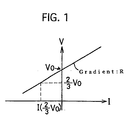
- Figure 1 is a graph which shows a current-voltage (I-V) characteristic.
- Figure 6 is a configuration which schematically shows an example of conductive network.
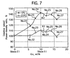
- Figure 7 is a graph which shows a relationship between an additive amount and power density ratio at 0 °C and 25 °C.
- Figure 8 is a graph which shows a hydrogen equilibrium pressure of hydrogen storage alloy in increasing Mn, Al in hydrogen storage alloy.
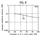
- Figure 9 is a graph which shows an equilibrium pressure of hydrogen storage alloy in increasing La in misch metal of hydrogen storage alloy.
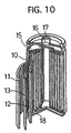
- Figure 10 is an analyzing drawing which shows an application example applied to a battery.
- the present inventor prepared alloys being compounded at an aimed composition ( it is expressed when "Mm” is 1 at a ratio of the number of atoms) shown by No.1-No.9 in Table 1.
- the present inventor melted this alloy by the arc melting method to form a solidified body, crushing the solidified body by a tungsten mortar to form powder of the hydrogen storage alloy, so that the powder was adjusted in such a manner that particle sizes of 45-75 ⁇ m occupy 60 wt% and the remainder is in the range of 45 ⁇ m or less.
- Base 1 Comparable Example A which is No. 1, was set to be a standard.
- Comparable Example B, No.2 shows the formula of (Ni+Al+Co+Mn) is 5.5, and "x" value is 0.5. Comparable Example B, No.2, shows a phase rate of the second phase is as small as 5.7 wt%.
- No.3-No.9 are correspondent to the present invention, the total quantity of ratio of the number of atoms of (Ni+Al+Co+Mn) is 6.0-9.0, and Ni is over 3.5, as shown in Table 1.
- phase rates are in the range of 9-33 wt%, respectively: it is comparatively abounding.
- the present inventor using the hydrogen storage alloy concerning No.3-No.9 corresponding to the present invention, examined an internal structure by X-ray diffraction (XRD).
- XRD X-ray diffraction
- these hydrogen storage alloys are composed of the hydrogen storage alloy phase expressed by the general formula of AB s, and the second phase having the crystal structure of the Ni type or the AlNi 3 type to has Ni- high content
- the second phase has a network state.
- Table 2 shows the producing technique concerning Examples 1-12.
- Table 2 also shows the producing technique concerning Comparable Example 1.
- the present inventor used 2.0-2.2g of the hydrogen storage alloy shown by No.1-No.9 in Table 1, respectively. Then, the present inventor formed a plurality of negative electrodes based on the producing technique of Examples 1-12 shown in Table 2. By combining this negative electrode and this positive electrode, the present inventor produced a negative electrode regulation battery having the sintered positive electrode. In this battery, a capacity ratio of ( positive electrode / negative electrode ) is more than 10.
- the present inventor charged it at 20 mA/g for 20 hours, and discharged it to 1V at 50 mA/g. After the first cycle, the present inventor charged it at 50 mA/g for 6 hours, discharged it to 1V, and successively repeated about 10 times until the capacity is saturated.
- SOC50% means a charging of 50% with respect to the full charge.
- the present inventor held the battery in a constant temperature oven (target temperature: at 0 °C and 25 °C) for 2 hours.
- Figure 1 shows an I-V characteristic property, namely, a current-voltage characteristic property.
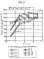
- the present inventor measured the power density of the battery with the negative electrode which is formed by producing technique concerning Examples 1-12.
- Figures 2 and 3 show the test results.
- Figure 2 shows the test results in 0 °C.
- Figure 3 shows the test results in 25°C.
- Comparable Example A in Figure 2 and Figure 3 is shown by mark of " ⁇ ".
- Comparable Example A means the battery including the negative electrode formed by using the hydrogen storage alloy having the No.1 composition ( conventional composition ) in Table 1, and by using the producing technique of Comparable Example 1 ( machine crushing + binder material + current collector ) in Table 2.
- the vertical line shows power density of ratio the battery, wherein it shows the relative value when the power density of battery produced by Comparable Example A is set at 100%.
- the test for measuring the power density ratio was executed with respect to the hydrogen storage alloys in which the "x" value is 0.5, 1.5, 2.5, and 3.5, respectively.
- the characteristic line of Figure 2 in which the test temperature is 0 °C, and the characteristic line of Figure 3 in which the test temperature is 25 °C, in the battery including the negative electrode produced by Examples 1-12 the right-increasing characteristics are obtained.
- the power density ratio of the battery becomes a decline, when the "x" value exceeds 4.
- the power density ratio is 130-135 %.
- the power density ratio sometimes exceeds 140 %.
- the power density ratio is improved in the characteristic line of Figure 2 than that in the characteristic line of Figure 3 - the test temperature in Figure 2 is 0 °C, and the test temperature in Figure 3 is 25 °C.
- Table 2 shows items of 1 ⁇ - 8 ⁇ as a producing technique. The items of 1 ⁇ - 8 ⁇ in Table 2 will be explained hereinafter.
- the present inventor melted the molten metal with the target alloy composition by an arc melting method, solidified it to form an ingot
- the alloy powder was produced in which 60 wt% of the whole powder was in the range of 45-75 ⁇ m in particle size, and the remainder is in the range of 45 ⁇ m or less.
- the present inventor melted the molten metal with the target alloy composition by an arc melting method, solidified it to form an ingot
- the present inventor crushed the ingot to be approximately 100 meshes by a crushing machine.
- the present inventor repeated hydrogen-storing treatment under a hydrogen atmosphere and hydrogen-emitting treatment As a result, the hydrogen storage alloy was crushed by means of hydrogenation so that the powder became in the range of under 300 mesh.
- the present inventor melted the molten metal with the target alloy composition, hitting the molten metal to a cooling roller by a roll quenching method to rapidly solidify the molten metal at a cooling speed over 10 5 K/sec.
- ribbon pieces ( wall thickness: 10 - 100 ⁇ m) were produced as a solidified piece having minute crystals of average particle size 10 ⁇ m or less.
- the present inventor executed a heat treatment in which ribbon pieces were kept at 1200 °C in an inert atmosphere ( argon gas atmosphere) for 60 minutes.
- the present inventor mechanically crushed the ribbon pieces after the heat treatment. Therefore, the alloy powder was produced in which 60wt% of the whole powder was in the range of 45-75 ⁇ m in particle size, and the remainder was in the range of 45 ⁇ m or less.
- the present inventor mechanically crushed the ribbon pieces after the heat treatment. Therefore, the alloy powder was produced in which 60wt% of the whole powder was in the range of 45-75 ⁇ m in particle size and the remainder was in the range of 45 ⁇ m or less.
- the present inventor repeated a hydrogen- storing treatment under a hydrogen atmosphere and a hydrogen-emitting treatment to produce the hydrogen storage alloy having the range of under 300 mesh by means of hydrogenation.
- the present inventor formed a slurry by mixing hydrogen storage alloy powder with binder material (carboxymethylcellulose ) working as a binder material, alcohol and water working as a solvent
- binder material carboxymethylcellulose
- the present inventor coated the slurry onto a current collector composed of porous nickel to dry it, compressing it in a plate shape (thickness : about 300 ⁇ m ) to form a electrode ( negative electrode ) by press-forming.
- the porous nickel is produced by burning an organic substance coated by a nickel film.
- the present inventor compressed an aggregate of the powder of hydrogen storage alloy to form a plate ( thickness : about 300 ⁇ m ) by press-forming. Afterwards, the present inventor supplied electric current to the compressed body in an inert atmosphere in a thickness direction so as to weld and sinter the contacting area of the powder particles by electric resistance welding.
- the electric current density was at 1A/cm 2 , and the welding time was about 2 seconds. According to this method, the second phases of powder particles adjoining each other is connected by the electric resistance welding.
- the present inventor compressed an aggregate of the hydrogen storage alloy powder to be about 300 ⁇ m in thickness to form a compressed body by press-forming. Afterwards, the present inventor sintered contacting areas in the powder particle by heating the compressed body in a sintering furnace - temperature was 1200 °C and heating time was 30 minutes - having a reducibility atmosphere in which hydrogen gas flows. This allows a good conductivity in the second phase of the powder particle.
- This inventor installed the negative electrode to the battery to measure the internal resistance of the battery.
- the internal resistance in 0 °C shows 80.4 %
- the internal resistance in 25 °C shows 78.2 %.
- the internal resistance in 0 °C shows 94.7 %
- the internal resistance in 25 °C shows 74.2 %. Therefore, the battery shows a good power in low-temperatures.
- the present inventor coated the slurry including the hydrogen storage alloy powder shown in the above-mentioned 6 ⁇ onto the electrode having a current collector composed of the porous nickel, pressing it to form the electrode.
- the current collector composed of the porous nickel has a larger conductive route. The reason is as follows: the organic substance covered with a nickel film is lost by burning, however, the nickel film remains. Such porous nickel has a limit in refining the electrically conductive route.
- the minute electrically conductive network is formed by the second phase in the inside of the powder particle of hydrogen storage alloy, as well as the electrical conductive route is constituted by the current collector. Therefore, the partial electric conductive dispersion is further reduced in the electrode, and the conductivity becomes uniform. This allows the electrode to reduce the internal resistance of the battery and to improve electrical conductivity.
- Next hydrogen storage alloy includes Mo, having the whole composition expressed by the formula of MmNi (3.55+i) Al (0.3+j) Co (0.75+k) Mn (0.4+l) Mo(m).
- the present inventor also carried out the similar test about this hydrogen storage alloy. That is to say, the standard is the hydrogen storage alloy having the composition of Comparable Example C, having Base 2 corresponding to No.10 shown in Table 4.
- Base 2 has the formula of MmNi 3.55 Al 0.3 Co 0.75 Mn 0.4 .
- No.10 Base 2 has a phase rate 0 wt% as for the second phase.
- Comparable Example D No.11, the "y” value is as small as 0.3, and the phase rate is 4.8 wt%.
- the present inventor adjusted alloying elements with respect to Base 2 to obtain the hydrogen storage alloys of No.12-No.17 corresponding to the present invention. In No.12 -No.17, the total quantity of ratio of the number of atoms of (Ni+Al+Co+Mn+Mo) is 5.8-7.8, and Ni is 3.5 or more.
- the present inventor examined the internal structure of hydrogen storage alloy concerning No.12-No.17, which correspond to the present invention, by X-ray diffraction (XRD).
- X-ray diffraction indicates that the hydrogen storage alloy is composed of the second phase having the crystal structure of ⁇ -NiMoCo type or Co 7 Mo 6 type, and that the hydrogen storage alloy phase is expressed by the general formula of AB 5 .
- the second phase is formed by the network to has rich conductivity.
- the present inventor Using the hydrogen storage alloy having the composition shown in Table 4, the present inventor respectively produced the negative electrodes by the producing technique concerning Examples 1-12 shown in Table 2. The present inventor similarly examined the battery having the negative electrodes about the power density ratio. In this case, the "y" value are 0.5, 1, 1.5, 2.5, respectively.
- Figures 4 and 5 show the test results of power density ratio of the battery having the negative electrode produced by the producing technique corresponding to Examples 1-12.
- Figure 4 shows the test result in 0 °C.
- Figure 5 shows the test results in 25 °C.
- Comparable Example C shown by a " ⁇ " mark in Figures 4 and 5 means the battery having the negative electrode which uses the hydrogen storage alloy of No.10 composition ( conventional composition ) shown in Table 4 and which uses Comparable Example 1 ( machine crushing + binder material + current collector ) shown in Table 2.
- the vertical line shows the relative value ; wherein power density of the battery with the negative electrode formed by the producing technique concerning Comparable Example C is set at 100%.
- the power density ratio increases in Examples 1-12, as understood from the characteristic lines of Figure 4 - Figure 4 shows a test temperature of 0 °C and Figure 5 shows a test temperature of 25 °C.
- the "y" value is in the range of 0.5-3, the result is good.
- the power density ratio increases, when the "y" value is at 1 and 1.5.
- the "y" value is excessive, the proportion of the hydrogen storage alloy phase relatively decreases, and the second phase having the good conductivity increases; so, the power density ratio of the battery became lower.
- the power density ratio is less than 140 %.
- the power density ratio sometimes exceeds 140%.
- Figure 4 showing a test temperature of 0 °C is improved than Figure 5 showing a test temperature of 25 °C in power density. Therefore, the hydrogen storage alloy concerning the present invention is improved in power characteristics in low- temperatures than that of the conventional technique.
- the hydrogen storage alloy concerning the present example is suitable to the battery for a hybrid automobile which mainly uses both of a motor and an internal combustion engine.
- the hybrid automobile requires that much electricity is charged and discharged with respect to the battery at one time. The ability is generally shown as battery power.
- the automobile has a restrict in volume and weight to demand compactification. Therefore, the battery used in the hybrid automobile requires high power density which means battery power per unit weight or per unit mass. In the general battery, power is lower in low- temperatures. Also, the automobile, being used in outdoor, requires power density in low-temperatures.
- the battery with the negative electrode composed of the hydrogen storage alloy having compositions shown in Table 1 good conductive network is obtained by the second phase, the internal resistance is reduced to improve electrical conductivity, and power density of the battery increases.
- the hydrogen storage alloy concerning the present invention can improve power in low- temperatures and high- speed charging.
- the hydrogen storage alloy has the hydrogen storage alloy phase and the second phase. It is assumed that the hydrogen storage alloy phase has the formula of MmNi 3.55 Al 0.30 Co 0.75 Mn 0.4 .
- the second phase has the remainder which is constituted by removing the composition of hydrogen storage alloy phase from the whole composition.
- the phase rate of second phase means "second phase / hydrogen storage alloy" by weight,.
- Figure 6 schematically shows an example of second phase with electrical conductivity.
- the second phase with conductivity forms a conductive network.
- the conductive network includes has both a two-dimensional network, and a three-dimensional network which is sometimes illustrated to have a cut in a two-dimensional cross section.
- an average value of "L" is minute, expressing a conductive network distance.
- the conductive network is minuter- the hydrogen storage alloy, which is rapidly solidified, precipitates the second phase in a grain boundary by heat-treatment
- the average value of "L” in many cases, does not exceed 30 ⁇ m, 20 ⁇ m, 10 ⁇ m, 7 ⁇ m, and 4 ⁇ m. This was confirmed by EPMA analysis.
- this hydrogen storage alloy is expressed by the formula of Mm-(Ni-Al-Co-Mn-Cu). So, the total quantity of (Ni-Al-Co-Mn-Cu) is expressed by 5.5 ⁇ (Ni+Al+Co+Mn+Cu) ⁇ 7.0, and 4.0 ⁇ Ni, when Mm is set at 1 by a ratio of the number of atoms.
- the structure is composed of the hydrogen storage alloy phase having the general formula of AB 5 , and the second phase which exists in the hydrogen storage alloy phase. In this case, the second phase generally has a crystal structure of Ni type or AlNi 3 type.
- Base 3 Comparable Example E, has the formula of MmNi 3.95 Al 0.3 Co 0.4 Mn 0.45 Cu 0.10 .
- the metallic additives containing Al, Ni, Co, Mn as a major component was used.
- the additives has a composition of Al 7.37 Ni 54.42 Co 17.36 Mn 20.86 .
- the adjusted range is expressed by 0.3 ⁇ (p+q+r+s+t) ⁇ 1.8.
- the present inventor formed ingots by solidifying the molten metal having the compositions of No.21-No.27 shown in Table 5, respectively.
- the present inventor crushed each of the ingots to produce the alloy powder.
- the present inventor formed the slurry by mixing CMC ( carboxymethylcellulose ) working as binder material, alcohol and water working as a solvent, and the above-mentioned alloy powder.
- the present inventor produced the negative electrode by coating the slurry onto pores of the current collector made of porous nickel. That is to say, the electrode ( negative electrode ) was produced based on the process of the item 1 ⁇ shown in Table 2, and the process of item 6 ⁇ shown in Table 2.
- Output density (W / kg) means power which can be generated per unit mass of battery.
- Figure 7 shows the test results.
- the vertical line of Figure 7 shows the relative power density ratio.
- the horizontal line of Figure 7 shows the additive amount being added to Base 3.
- “Addi. 10 wt%”, namely, additives 10 wt%, means the composition of Base 3 90wt% and additive 10wt%.
- the characteristic line R1 shows power density ratio in 25 °C
- the characteristic line R2 shows power density in 0 °C.
- the power density ratio of the battery increases with an increase of the additives.
- the characteristic line R2 exhibits an increasing tendency in power density ratio.
- the present mode of hydrogen storage alloy shows improvement power of the battery in low-temperatures.
- the additive amount is represented by "Kx”
- 5 wt% ⁇ Kx ⁇ 17 wt% is preferable.
- 8 wt% ⁇ Kx ⁇ 15 wt% is preferable. In other words, the vicinity of No.23, No.24, No.25, No.26 and No.27 are good.
- Figure 7 shows that No.24 ( additives : 10 wt % ), namely Base 4, is best in power density. So, using No.24 as a basic material, the present inventor added Mn to No.24 to adjust No.28-No.30 compositions shown in Table 5. In No. 28, “ Add 0.2 Mn” means that 0.2 of Mn is added to the composition of Base 4 when Mm is set at 1 by ratio of the number of atoms. Then, the present inventor solidifies the molten metal concerning No.28- No.30 to form ingots, forming the powder of hydrogen storage alloy by crushing the ingot.
- the present inventor carried out a hydrogen equilibrium pressure test ( test temperature: 40 °C ) to measure P-T-C characteristics (pressure-hydrogen concentration-isothermal diagram ) and to obtain a hydrogen equilibrium pressure based on this characteristics. Similarly, the present inventor adjusted the compositions concerning No.31-No.33 shown in Table 5, by increasing Al to Base 4. In No.31, " Add 02 Al" " means that 02 of Al is added to the composition of Bases 4 when Mm is set at 1 by ratio of the number of atoms.
- the present inventor solidified the molten metal concerning No.31-No.33 to form ingots, forming the powder of hydrogen storage alloy by crushing the ingot.
- the present inventor carried out the hydrogen equilibrium pressure test ( test temperature : 40 °C ) to measure P-T-C characteristics.
- Figure 8 shows these test results.
- the horizontal line of Figure 8 shows a ratio of the number of atoms of Al or Mn added to the composition of Base 4, when Mm is set at 1 by ratio of the number of atoms.
- the vertical line of Figure 8 shows a hydrogen equilibrium pressure of the hydrogen storage alloy.
- the characteristic line R3 of Figure 8 shows changes of hydrogen equilibrium pressure of hydrogen storage alloy when Al increases.
- the characteristic line R4 of Figure 8 shows changes of the hydrogen equilibrium pressure of hydrogen storage alloy when Mn increases.
- Figure 8 indicates that the hydrogen equilibrium pressure of hydrogen storage alloy gradually decreases with an increase of Mn and Al.
- the present inventor produced hydrogen storage alloys in which ratios of La being occupied in misch metal concerning Base 4 were changed to 60%, 70%, 80%, 90% (No.34), and 100% (No.35), respectively.
- the present inventor produced the powder of hydrogen storage alloy by the above- mentioned procedure, carrying out the hydrogen equilibrium pressure test ( test temperature : 40 °C ) to measure a hydrogen equilibrium pressure.
- Figure 9 shows this test results.
- the horizontal line shows the proportion of La being occupied in the misch metal
- the vertical line shows a hydrogen equilibrium pressure of hydrogen storage alloy.
- the characteristic line 5 of Figure 9 indicates that the hydrogen equilibrium pressure of hydrogen storage alloy gradually decreases when the proportion of La being occupied in misch metal is increased.
- Figure 10 shows an example in which a nickel-hydrogen battery having a closed- type.
- a container 10 having the negative electrode 11 composed of the above-mentioned hydrogen storage alloy and the positive electrode 12 mainly composed of Ni.
- the positive electrodes 12 and the negative electrode 11 are partitioned by separators 13 formed by nonwoven fabric such as polypropylene.
- the container 10 holds an alkali aqueous solution (KOH solution) working as an electrolyte.
- KOH solution alkali aqueous solution
- the battery concerning this example is an alkaline battery.
- the present invention can be utilize as hydrogen storage alloy, a hydrogen storage alloy electrode, and a battery. Especially, it is possible to utilize a hydrogen storage alloy, a hydrogen storage alloy electrode, and a battery for an automobile which is sometimes used in low-temperatures.
Landscapes
- Chemical & Material Sciences (AREA)
- Chemical Kinetics & Catalysis (AREA)
- Electrochemistry (AREA)
- General Chemical & Material Sciences (AREA)
- Battery Electrode And Active Subsutance (AREA)
- Powder Metallurgy (AREA)
- Manufacture Of Metal Powder And Suspensions Thereof (AREA)
Claims (15)
- Alliage emmagasinant l'hydrogène comprenant:une composition principale exprimée par la formule de Mm-(Ni-Al-Co-Mn), en particulier par la formule de MmNi(3,55+a) Al(0,3+b) Co(0,75+c) Mn (0,4+d), et 0,5<(a+b+c+d) ≤ 4.un rapport entre les divers nombres d'atomes exprimés par la formule de (Ni-Al-Co-Mn) est présenté comme 5,5<(Ni+Al+Co+Mn) ≤9, et 3,5 ≤Ni, lorsque Mm est établi à 1 en rapport entre les divers nombres d'atomes; etune structure interne comprenant une phase d'alliage emmagasinant l'hydrogène exprimée par la formule de AB5, et une seconde phase existante dans ladite phase d'alliage emmagasinant l'hydrogène.
- Alliage emmagasinant l'hydrogène selon la revendication 1, dans lequel ladite seconde phase possédant une structure cristalline présente un type Ni ou un type AlNi3.
- Alliage emmagasinant l'hydrogène comprenant:une composition principale exprimée par la formule de Mm-(Ni-Al-Co-Mn-Mo), en particulier par la formule de MmNi(3,55+i) Al(0,3+j) Co(0,75+k) Mn(0,4+l) Mo(m), et 0,5<(i+j+k+l+m)≤3.un rapport entre les divers nombres d'atomes exprimés par la formule de (Ni-Al-Co-Mn-Mo) est présenté comme 5,5<(Ni+Al+Co+Mn+Mo) ≤8, et 3,5 ≤ Ni, lorsque Mm est établi à 1 en rapport entre les divers nombres d'atomes; etune structure interne comprenant une phase d'alliage emmagasinant l'hydrogène exprimée par la formule générale de AB5 et une seconde phase existante dans ladite phase d'alliage emmagasinant l'hydrogène.
- Alliage emmagasinant l'hydrogène selon la revendication 3, dans lequel ladite seconde phase possédant une structure cristalline présente un type µ-NiMoCo ou un type Co7 Mo6.
- Alliage emmagasinant l'hydrogène comprenant:une composition d'alliage principale composée par la formule de Mm-(Ni-Al+Co+Mn+Cu), en particulier par la formule de MmNi(3,95+p) Al(0,3+q) Co(0,4+r) Mn(0,45+s) Cu(0,10+t), et 0,3<(p+q+r+s+t) ≤ 1,8.un rapport entre divers nombre d'atomes exprimé par la formule de (Ni-Al-Co-Mn-Cu) est représenté par 5,5<(Ni+Al+Co+Mn+Cu)≤7,0, et 4,0≤Ni, lorsque Mm est établi à 1 en rapport entre les divers nombres d'atomes; etune structure interne comprenant une phase d'alliage emmagasinant l'hydrogène exprimée par la formule générale de AB5 et une seconde phase existante dans ladite phase d'alliage emmagasinant l'hydrogène.
- Alliage emmagasinant l'hydrogène selon la revendication 5, dans lequel ladite seconde phase possédant une structure cristalline présente un type Ni ou un type AlNi3.
- Alliage emmagasinant l'hydrogène selon la revendication 5, dans lequel ladite composition satisfait au moins l'une des deux conditions (q>0,06) et (s>0,18), "q" concernant Al et "s" concernant Mn.
- Alliage emmagasinant l'hydrogène selon l'une des revendications 5 à 7, dans lequel La occupe au moins 60 % en poids dans Mm.
- Procédé de production d'alliage emmagasinant l'hydrogène qui comprend les étapes de:emploi d'un métal fondu dudit alliage emmagasinant l'hydrogène selon l'une desdites revendications 1 à 8;solidification dudit métal fondu à une vitesse de refroidissement rapide pour former un alliage emmagasinant l'hydrogène solidifié; etmaintien dudit alliage emmagasinant l'hydrogène solidifié dans une plage allant de 1 000 à 1 200° C pendant 30 minutes à 120 heures pour précipiter une seconde phase ayant un état de réseau.
- Procédé de production d'un alliage emmagasinant l'hydrogène qui comprend les étapes de:emploi de métal fondu dudit alliage emmagasinant l'hydrogène selon l'une desdites revendications 1 à 8,solidification dudit métal fondu pour former un corps massif;écrasement dudit corps massif pour former un alliage emmagasinant l'hydrogène écrasé; ethydrogénation dudit alliage emmagasinant l'hydrogène écrasé pour écrasement supplémentaire.
- Electrode d'alliage emmagasinant l'hydrogène, caractérisée par un matériau constitué dudit alliage emmagasinant l'hydrogène selon l'une desdites revendications 1 à 8.
- Procédé de production d'électrode d'alliage emmagasinant l'hydrogène qui comprend les étapes de:emploi dudit alliage emmagasinant l'hydrogène ayant une forme poudreuse et ayant une composition selon l'une desdites revendications 1 à 8;formation d'un mélange dans lequel ledit alliage emmagasinant l'hydrogène et le matériau agissant comme liant sont mélangés; etcombinaison dudit mélange avec un collecteur de courant pour former une électrode d'alliage emmagasinant l'hydrogène.
- Procédé de production d'électrode d'alliage emmagasinant l'hydrogène qui comprend les étapes de:emploi d'un alliage emmagasinant l'hydrogène ayant une forme poudreuse et ayant une composition selon l'une desdites revendications 1 à 8;combinaison dudit alliage emmagasinant l'hydrogène avec un collecteur de courant sans utilisation de matériau agissant comme liant; etfrittage dudit alliage emmagasinant l'hydrogène avec ledit collecteur de courant pour former une électrode d'alliage emmagasinant l'hydrogène.
- Procédé de production d'électrode d'alliage emmagasinant l'hydrogène qui comprend les étapes de:emploi d'un alliage emmagasinant l'hydrogène avec une forme poudreuse et ayant une composition selon l'une desdites revendications 1 à 8;compression dudit alliage emmagasinant l'hydrogène par moulage sous pression pour former un corps comprimé sans utilisation d'un matériau agissant comme liant et sans utilisation d'un collecteur de courant; etfrittage dudit corps comprimé pour former une électrode d'alliage emmagasinant l'hydrogène.
- Batterie comprenant une électrode négative générant une réaction d'électrodes négatives et une électrode positive générant une réaction d'électrodes positives, dans laquelle ladite électrode négative est caractérisée par ledit alliage emmagasinant l'hydrogène ayant une composition selon l'une desdites revendications 1 à 8.
Applications Claiming Priority (3)
| Application Number | Priority Date | Filing Date | Title |
|---|---|---|---|
| JP35895597 | 1997-12-26 | ||
| JP35895597 | 1997-12-26 | ||
| PCT/JP1998/005934 WO1999034025A1 (fr) | 1997-12-26 | 1998-12-24 | Alliages absorbant l'hydrogene, procedes de production de ces alliages, electrode realisee a l'aide de cet alliage et procede de fabrication et accumulateur |
Publications (3)
| Publication Number | Publication Date |
|---|---|
| EP0965652A1 EP0965652A1 (fr) | 1999-12-22 |
| EP0965652A4 EP0965652A4 (fr) | 2001-01-10 |
| EP0965652B1 true EP0965652B1 (fr) | 2003-02-26 |
Family
ID=18461981
Family Applications (1)
| Application Number | Title | Priority Date | Filing Date |
|---|---|---|---|
| EP98961578A Expired - Lifetime EP0965652B1 (fr) | 1997-12-26 | 1998-12-24 | Alliages absorbant l'hydrogene, procedes de production de ces alliages, electrode realisee a l'aide de cet alliage et procede de fabrication et accumulateur |
Country Status (7)
| Country | Link |
|---|---|
| US (3) | US6602639B1 (fr) |
| EP (1) | EP0965652B1 (fr) |
| JP (1) | JP3300373B2 (fr) |
| CN (3) | CN1187852C (fr) |
| CA (1) | CA2281600C (fr) |
| DE (1) | DE69811638T2 (fr) |
| WO (1) | WO1999034025A1 (fr) |
Families Citing this family (11)
| Publication number | Priority date | Publication date | Assignee | Title |
|---|---|---|---|---|
| JP3881823B2 (ja) * | 2000-06-09 | 2007-02-14 | 三井金属鉱業株式会社 | 水素吸蔵合金及びその製造方法 |
| US6500583B1 (en) * | 2000-07-17 | 2002-12-31 | Energy Conversion Devices, Inc. | Electrochemical hydrogen storage alloys for nickel metal hydride batteries, fuel cells and methods of manufacturing same |
| US6820706B2 (en) * | 2001-09-25 | 2004-11-23 | Energy Conversion Devices, Inc. | Method and system for hydrogen powered internal combustion engine |
| JP5300265B2 (ja) * | 2004-12-07 | 2013-09-25 | ザ ユニバーシティー オブ クイーンズランド | 水素吸蔵のためのマグネシウム合金 |
| DE102007009295A1 (de) * | 2007-02-16 | 2008-08-21 | Varta Microbattery Gmbh | Galvanisches Element mit hoher Kapazität |
| CN101570314B (zh) * | 2008-05-04 | 2011-07-13 | 比亚迪股份有限公司 | 一种储氢材料的制备方法 |
| US8940436B2 (en) | 2008-10-17 | 2015-01-27 | National Institute Of Advanced Industrial Science And Technology | Sulfur-modified polyacrylonitrile, manufacturing method therefor, and application thereof |
| AU2011220329B2 (en) | 2010-02-24 | 2016-11-24 | Hydrexia Pty Ltd | Hydrogen release system |
| CN107848027A (zh) | 2015-07-23 | 2018-03-27 | 海德瑞克斯亚股份有限公司 | 用于储氢的Mg基合金 |
| CN112458351B (zh) * | 2020-10-22 | 2021-10-15 | 中国人民解放军陆军装甲兵学院 | 高抗压强度的镍钴基高温合金 |
| US11266965B1 (en) | 2021-01-14 | 2022-03-08 | Shandong University | Ultra-low-speed rotating low-strain high-filling-rate hydrogen storage alloy reaction device and technology |
Family Cites Families (30)
| Publication number | Priority date | Publication date | Assignee | Title |
|---|---|---|---|---|
| JPS60250558A (ja) | 1984-05-25 | 1985-12-11 | Matsushita Electric Ind Co Ltd | 密閉形アルカリ蓄電池 |
| JPH0763007B2 (ja) | 1987-05-22 | 1995-07-05 | 松下電器産業株式会社 | 水素吸蔵電極の製造法 |
| NL8901776A (nl) | 1989-07-11 | 1991-02-01 | Philips Nv | Elektrochemische cel. |
| WO1992008251A1 (fr) * | 1990-10-29 | 1992-05-14 | Yuasa Corporation | Electrode d'accumulation d'hydrogene, electrode au nickel, et accumulateur nickel-hydrogene |
| JP2926965B2 (ja) * | 1990-10-31 | 1999-07-28 | 新神戸電機株式会社 | 水素吸蔵合金 |
| JP3123106B2 (ja) | 1991-04-26 | 2001-01-09 | 新神戸電機株式会社 | ニッケル・水素電池用水素吸蔵合金およびその製造法 |
| CN1029809C (zh) * | 1991-12-28 | 1995-09-20 | 南开大学 | 储氢合金电极 |
| US5185221A (en) * | 1992-02-06 | 1993-02-09 | Gates Energy Products, Inc. | Metal hydride electrode and electrochemical cell |
| CN1033654C (zh) * | 1992-05-16 | 1996-12-25 | 上海工业大学 | 一种贮氢电极合金 |
| JP3369226B2 (ja) | 1992-11-09 | 2003-01-20 | 東芝電池株式会社 | 金属酸化物・水素二次電池 |
| FR2698881B1 (fr) * | 1992-12-04 | 1995-01-13 | Accumulateurs Fixes | Matériau hydrurable pour électrode négative d'accumulateur nickel-hydrure. |
| JP3095101B2 (ja) * | 1993-03-05 | 2000-10-03 | 信越化学工業株式会社 | 水素吸蔵合金及びそれを用いた電極 |
| JP2820859B2 (ja) | 1993-04-16 | 1998-11-05 | 山陽特殊製鋼株式会社 | 水素吸蔵合金粉末の製造方法 |
| JPH0750163A (ja) | 1993-05-31 | 1995-02-21 | Sanyo Electric Co Ltd | 水素吸蔵合金電極及び水素吸蔵合金電極の製造方法 |
| US5529857A (en) * | 1993-10-06 | 1996-06-25 | Sanyo Electric Co., Ltd. | Hydrogen-absorbing alloy electrode and process for producing the same |
| JPH07157813A (ja) | 1993-12-03 | 1995-06-20 | Mazda Motor Corp | 水素吸蔵合金の活性化処理方法 |
| JP3377591B2 (ja) | 1994-02-15 | 2003-02-17 | 東芝電池株式会社 | 金属酸化物・水素二次電池の製造方法 |
| JP2965475B2 (ja) | 1994-02-28 | 1999-10-18 | 松下電器産業株式会社 | 水素吸蔵合金 |
| JPH07258703A (ja) | 1994-03-18 | 1995-10-09 | Matsushita Electric Ind Co Ltd | 水素吸蔵合金粉末およびその製造方法 |
| JP3730265B2 (ja) * | 1994-04-01 | 2005-12-21 | 株式会社東芝 | 電池用水素吸蔵合金,その製造方法およびニッケル水素電池 |
| JP2655074B2 (ja) | 1994-04-08 | 1997-09-17 | 工業技術院長 | 水素吸蔵合金及びその電極 |
| JPH09209065A (ja) * | 1994-11-07 | 1997-08-12 | Santoku Kinzoku Kogyo Kk | 時効析出型希土類金属−ニッケル系合金、その製造法及びニッケル水素2次電池用負極 |
| JPH08250115A (ja) | 1995-03-10 | 1996-09-27 | Toshiba Battery Co Ltd | アルカリ二次電池 |
| EP0765947B1 (fr) * | 1995-04-03 | 2001-10-17 | Santoku Metal Industry Co., Ltd. | Alliage absorbant l'hydrogene a base de nickel et de metaux du groupe des terres rares, son procede de fabrication et electrode negative pour batterie secondaire nickel-hydrogene |
| JPH08315815A (ja) | 1995-05-22 | 1996-11-29 | Sanyo Electric Co Ltd | アルカリ蓄電池用水素吸蔵合金の作製方法 |
| JPH08315813A (ja) | 1995-05-22 | 1996-11-29 | Sanyo Electric Co Ltd | アルカリ蓄電池用の水素吸蔵合金電極 |
| JP3473926B2 (ja) | 1995-07-24 | 2003-12-08 | 三井金属鉱業株式会社 | 水素吸蔵合金およびその製造方法 |
| JPH0997607A (ja) | 1995-09-29 | 1997-04-08 | Toshiba Corp | 電池用水素吸蔵合金,その製造方法およびニッケル水素二次電池 |
| DE19639440C2 (de) * | 1995-09-29 | 2001-05-10 | Toshiba Kawasaki Kk | Wasserstoff absorbierende Legierung für eine Batterie und Verwendung der Legierung in Sekundär-Nickel-Metallhydrid-Batterien |
| DE69727317T2 (de) * | 1996-09-06 | 2004-11-25 | Santoku Corp., Kobe | Wasserstoffabsorbierende seltene-erden metall/nickel-legierung, herstellungsverfahren und negative elektrode für nickel-wasserstoff-wiederaufladbare-batterie |
-
1998
- 1998-12-24 EP EP98961578A patent/EP0965652B1/fr not_active Expired - Lifetime
- 1998-12-24 DE DE69811638T patent/DE69811638T2/de not_active Expired - Lifetime
- 1998-12-24 CA CA002281600A patent/CA2281600C/fr not_active Expired - Fee Related
- 1998-12-24 US US09/367,932 patent/US6602639B1/en not_active Expired - Fee Related
- 1998-12-24 WO PCT/JP1998/005934 patent/WO1999034025A1/fr not_active Ceased
- 1998-12-24 JP JP51768599A patent/JP3300373B2/ja not_active Expired - Fee Related
- 1998-12-24 CN CNB011197293A patent/CN1187852C/zh not_active Expired - Fee Related
- 1998-12-24 CN CN98804424A patent/CN1078909C/zh not_active Expired - Fee Related
-
2001
- 2001-05-26 CN CNB011197285A patent/CN1134549C/zh not_active Expired - Fee Related
-
2003
- 2003-03-24 US US10/394,229 patent/US7223497B2/en not_active Expired - Fee Related
- 2003-03-24 US US10/394,036 patent/US6942947B2/en not_active Expired - Fee Related
Also Published As
| Publication number | Publication date |
|---|---|
| US6942947B2 (en) | 2005-09-13 |
| CN1252843A (zh) | 2000-05-10 |
| JP3300373B2 (ja) | 2002-07-08 |
| CA2281600C (fr) | 2005-02-08 |
| CN1358876A (zh) | 2002-07-17 |
| US20030175590A1 (en) | 2003-09-18 |
| CN1134549C (zh) | 2004-01-14 |
| EP0965652A1 (fr) | 1999-12-22 |
| CN1187852C (zh) | 2005-02-02 |
| US20030205300A1 (en) | 2003-11-06 |
| DE69811638D1 (de) | 2003-04-03 |
| US6602639B1 (en) | 2003-08-05 |
| CA2281600A1 (fr) | 1999-07-08 |
| WO1999034025A1 (fr) | 1999-07-08 |
| DE69811638T2 (de) | 2003-09-18 |
| US7223497B2 (en) | 2007-05-29 |
| EP0965652A4 (fr) | 2001-01-10 |
| CN1078909C (zh) | 2002-02-06 |
| CN1356735A (zh) | 2002-07-03 |
Similar Documents
| Publication | Publication Date | Title |
|---|---|---|
| Hu et al. | Annealing effect on phase composition and electrochemical properties of the Co-free La2MgNi9 anode for Ni-metal hydride batteries | |
| US9219277B2 (en) | Low Co hydrogen storage alloy | |
| EP1253654B1 (fr) | Alliage pour le stockage d'hydrogene, batterie secondaire, voiture hybride et vehicule electrique | |
| US8277582B2 (en) | Hydrogen absorbing alloy, hydrogen absorbing alloy electrode, secondary battery, and production method of hydrogen absorbing alloy | |
| JPH11323469A (ja) | 水素吸蔵合金及び二次電池 | |
| JP2006152442A (ja) | 異質粉末粒子を含有する電気化学的水素貯蔵合金及び電池 | |
| US6602639B1 (en) | Process for producing hydrogen storage alloy and process for producing hydrogen storage alloy electrode | |
| KR101857055B1 (ko) | 수소 흡장 합금 분말, 부극 및 니켈수소 2차전지 | |
| JP2002105563A (ja) | 水素吸蔵合金およびそれを用いたニッケル−水素二次電池 | |
| JP4642967B2 (ja) | 水素吸蔵合金電極の製造方法、アルカリ二次電池の製造方法、ハイブリッドカー及び電気自動車 | |
| US8021606B2 (en) | Hydrogen storage alloy, its production method, hydrogen storage alloy electrode, and secondary battery | |
| JPWO1999034025A1 (ja) | 水素吸蔵合金、水素吸蔵合金の製造方法、水素吸蔵合金電極、水素吸蔵合金電極の製造方法、及び電池 | |
| EP0755898B1 (fr) | Alliage pour le stockage de l'hydrogène et électrode à base d'un tel alliage | |
| EP1075032A1 (fr) | Alliage absorbant l'hydrogène et batterie secondaire au nickel-hydrure de métal | |
| JP3965209B2 (ja) | 低Co水素吸蔵合金 | |
| JPH0641663A (ja) | 水素吸蔵合金とその製造方法および水素吸蔵合金電極 | |
| JP3123106B2 (ja) | ニッケル・水素電池用水素吸蔵合金およびその製造法 | |
| JP5161451B2 (ja) | 水素吸蔵合金、それを用いた電極、およびニッケル水素二次電池 | |
| JP3816138B2 (ja) | 金属酸化物−金属水素化物のアルカリ電池及び該電池用の水素蓄積性合金負極の製造方法 | |
| JPH06176756A (ja) | 電池用水素吸蔵合金電極 | |
| JPH0953137A (ja) | 水素吸蔵合金および水素吸蔵合金電極 | |
| JPH08329941A (ja) | 水素吸蔵合金及びそれを用いた水素吸蔵合金電極 | |
| JPH10287942A (ja) | チタン系水素吸蔵合金と二次電池用電極 | |
| JPH08185859A (ja) | 密閉型金属−水素化物アルカリ蓄電池用の水素吸蔵合金電極 |
Legal Events
| Date | Code | Title | Description |
|---|---|---|---|
| PUAI | Public reference made under article 153(3) epc to a published international application that has entered the european phase |
Free format text: ORIGINAL CODE: 0009012 |
|
| 17P | Request for examination filed |
Effective date: 19990816 |
|
| AK | Designated contracting states |
Kind code of ref document: A1 Designated state(s): DE FR GB |
|
| A4 | Supplementary search report drawn up and despatched |
Effective date: 20001127 |
|
| AK | Designated contracting states |
Kind code of ref document: A4 Designated state(s): DE FR GB |
|
| RIC1 | Information provided on ipc code assigned before grant |
Free format text: 7C 22C 19/00 A, 7C 22F 1/10 B, 7B 22F 3/11 B, 7B 22F 9/04 B, 7H 01M 4/38 B, 7C 22C 1/04 B, 7C 22C 19/03 B, 7H 01M 4/26 B |
|
| 17Q | First examination report despatched |
Effective date: 20010914 |
|
| GRAH | Despatch of communication of intention to grant a patent |
Free format text: ORIGINAL CODE: EPIDOS IGRA |
|
| GRAH | Despatch of communication of intention to grant a patent |
Free format text: ORIGINAL CODE: EPIDOS IGRA |
|
| GRAA | (expected) grant |
Free format text: ORIGINAL CODE: 0009210 |
|
| AK | Designated contracting states |
Designated state(s): DE FR GB |
|
| REG | Reference to a national code |
Ref country code: GB Ref legal event code: FG4D |
|
| REF | Corresponds to: |
Ref document number: 69811638 Country of ref document: DE Date of ref document: 20030403 Kind code of ref document: P |
|
| ET | Fr: translation filed | ||
| PLBE | No opposition filed within time limit |
Free format text: ORIGINAL CODE: 0009261 |
|
| STAA | Information on the status of an ep patent application or granted ep patent |
Free format text: STATUS: NO OPPOSITION FILED WITHIN TIME LIMIT |
|
| 26N | No opposition filed |
Effective date: 20031127 |
|
| REG | Reference to a national code |
Ref country code: GB Ref legal event code: 746 Effective date: 20061025 |
|
| PGFP | Annual fee paid to national office [announced via postgrant information from national office to epo] |
Ref country code: GB Payment date: 20091223 Year of fee payment: 12 Ref country code: FR Payment date: 20091221 Year of fee payment: 12 |
|
| PGFP | Annual fee paid to national office [announced via postgrant information from national office to epo] |
Ref country code: DE Payment date: 20091217 Year of fee payment: 12 |
|
| GBPC | Gb: european patent ceased through non-payment of renewal fee |
Effective date: 20101224 |
|
| REG | Reference to a national code |
Ref country code: FR Ref legal event code: ST Effective date: 20110831 |
|
| PG25 | Lapsed in a contracting state [announced via postgrant information from national office to epo] |
Ref country code: FR Free format text: LAPSE BECAUSE OF NON-PAYMENT OF DUE FEES Effective date: 20110103 |
|
| PG25 | Lapsed in a contracting state [announced via postgrant information from national office to epo] |
Ref country code: DE Free format text: LAPSE BECAUSE OF NON-PAYMENT OF DUE FEES Effective date: 20110701 Ref country code: GB Free format text: LAPSE BECAUSE OF NON-PAYMENT OF DUE FEES Effective date: 20101224 |
|
| REG | Reference to a national code |
Ref country code: DE Ref legal event code: R119 Ref document number: 69811638 Country of ref document: DE Effective date: 20110701 |