EP0965826A1 - Capteur de temperature et procede de fabrication - Google Patents
Capteur de temperature et procede de fabrication Download PDFInfo
- Publication number
- EP0965826A1 EP0965826A1 EP99900155A EP99900155A EP0965826A1 EP 0965826 A1 EP0965826 A1 EP 0965826A1 EP 99900155 A EP99900155 A EP 99900155A EP 99900155 A EP99900155 A EP 99900155A EP 0965826 A1 EP0965826 A1 EP 0965826A1
- Authority
- EP
- European Patent Office
- Prior art keywords
- temperature sensor
- metal cylinder
- ceramic substrate
- sensor according
- inorganic filler
- Prior art date
- Legal status (The legal status is an assumption and is not a legal conclusion. Google has not performed a legal analysis and makes no representation as to the accuracy of the status listed.)
- Withdrawn
Links
Images


Classifications
-
- G—PHYSICS
- G01—MEASURING; TESTING
- G01K—MEASURING TEMPERATURE; MEASURING QUANTITY OF HEAT; THERMALLY-SENSITIVE ELEMENTS NOT OTHERWISE PROVIDED FOR
- G01K7/00—Measuring temperature based on the use of electric or magnetic elements directly sensitive to heat ; Power supply therefor, e.g. using thermoelectric elements
- G01K7/16—Measuring temperature based on the use of electric or magnetic elements directly sensitive to heat ; Power supply therefor, e.g. using thermoelectric elements using resistive elements
- G01K7/22—Measuring temperature based on the use of electric or magnetic elements directly sensitive to heat ; Power supply therefor, e.g. using thermoelectric elements using resistive elements the element being a non-linear resistance, e.g. thermistor
Definitions
- the present invention relates to temperature sensors and methods of manufacturing the same.
- a type of temperature sensor that uses a thin film thermistor element as a temperature-sensing element is disclosed, for example, in Japanese Patent Reissued Publication, No. H08-835932, and the like.
- Fig. 19 is a schematic cross sectional view depicting a structure of a temperature sensor of such kind.
- a temperature-sensing element 51 comprises a thin film of sintered ceramic formed on a substrate. Connecting parts for electric resistance of the temperature-sensing element 51 are formed of platinum film, and connected to lead wires 65 and 66 made of platinum.
- the lead wires 65 and 66 are housed within a metal housing 63 of a cylindrical shape, while being isolated with each other by electrical insulating glasses 61 and 62.
- the cylindrical metal housing 63 is fixed to a flange 64.
- the temperature sensor detects temperature electrically as a resistance of the temperature-sensing element 51.
- the sensor can constitute a characteristically suitable temperature sensor, including reliability.
- it makes an extremely expensive temperature sensor in respect of cost effectiveness, since it uses platinum wires for the lead wires 65 and 66. Because the platinum wires actually used for one temperature sensor has weighed approximately 0.54 gr, the temperature sensor has cost approximately 800 yen for the platinum alone based on the platinum price (approx. 1,500 yen/gr) as of July, 1997. The prior art techniques thus have had a problem of making temperature sensors very expensive.
- the present invention is intended to solve the above-cited problem of the prior art, and aims at providing a low-cost high-performance temperature sensor with high yield.
- a temperature sensor of the present invention includes: (a) a metal cylinder; (b) a ceramic substrate inserted in the metal cylinder, and provided with a temperature detecting element in a form of film and electrodes in a form of film for electrically tapping off an output of the temperature detecting element; (c) a supporting means having a function of reducing stress for supporting the ceramic substrate in the metal cylinder; and (d) a protective cap provided on one end of the metal cylinder for protecting the temperature detecting element provided on the ceramic substrate.
- the above structure is able to realize a low-cost high-performance temperature sensor with high yield.
- FIG. 1 A first exemplary embodiment of the present invention is described hereinafter by referring to Fig. 1 through Fig. 5.
- FIG. 1 through Fig. 3 respectively depict a schematic cross sectional view of a structure of a temperature sensor of the first exemplary embodiment of the present invention, a schematic view depicting a temperature detecting portion of the temperature sensor of Fig. 1, and a cross sectional view of the temperature detecting portion of Fig.2 after the fabrication.
- a reference numeral 1 represents a metal cylinder made of heat resistant stainless steel having an outer diameter of 3 mm and a thickness of 0.4 mm, in which a ceramic substrate 2 made of alumina having a length longer than the metal cylinder 1 is inserted.
- a tip portion of the ceramic substrate 2 is provided with a temperature detecting element 3 in a form of film formed by a CVD method.
- the temperature detecting element 3 used in this exemplary embodiment was a thermistor composed of an oxide-composite of Al, Cr and Fe.
- the temperature detecting element 3 is provided with a pair of electrodes 4 in a form of film formed on its surface for electrically detecting a resistance.
- the electrodes 4 were formed by printing and sintering platinum paste in this exemplary embodiment.
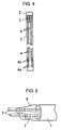
- An enlarged view of the electrodes 4 is shown in Fig. 4. Connecting portions of the electrodes, or portions to be soldered, are shown as electric conductors 4a containing glass, which was formed by printing and sintering only conductive paste of silver-palladium containing glass.
- the inorganic filler 5 was formed by injecting a predetermined amount of filling material of pasty form containing silica and Li 2 O besides a chief ingredient of alumina, with a dispenser, in the space between the metal cylinder 1 and the ceramic substrate 2, followed by hardening at 150 °C.
- a protective cap 6 made of nickel-chromium alloy is inserted, crimped and welded to the metal cylinder over a portion of the temperature detecting element 3 formed on the ceramic substrate 2, in order to protect the temperature detecting element 3.
- the protective cap 6 is provided with two holes 6a as shown in Fig. 2.
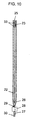
- the electric conductors 4a containing glass are connected by soldering to lead wires 7 covered by Teflon resin, and the soldered portions are totally molded with polyimide resin 8 in a such manner to also cover a portion of the lead wires 7.
- the foregoing configuration is shown in Fig. 5.
- the lead wires 7 are additionally secured by an insulator 9 composed of glass fiber-reinforced resin.
- 10 represents a nut attached to an outer periphery of the metal cylinder 1 for a purpose of mounting the temperature sensor.
- Detection of a temperature was made electrically as a change in resistance value of the temperature detecting element 3 to the temperature.
- a prototype temperature sensor having the foregoing structure was built, and evaluated for its output characteristics. As a result, it was confirmed that the prototype exhibits an equivalent performance with the prior art device for not only the principal characteristic of change in resistance to temperature, but also reliability.
- the prototype also attained an improvement of 30 to 40 % in responsivity as compared to the prior art device. This improvement is attributed to the holes 6a provided in the protective cap 6, which conduct the change in temperature directly to the temperature detecting element 3.
- the prototype could also realize a substantial reduction to one twentieth or less as compared to the platinum wires (approx. 800 yen) of the prior art device, since it uses approx. 0.01 g of the platinum paste, which costs approx. 35 yen as calculated based on price of the platinum paste (approx. 3,500 yen/gr).
- the inorganic filler 5 containing silica and Li 2 O besides the chief ingredient of alumina could be a single substance such as alumina or silica, or zirconia. Or, it could be a combination of them. This is for a reason that any of the foregoing substances have properties of good electrical insulation as well as good supporting capability for the ceramic substrate 2 under a high temperature environment. Further, a reason for the addition of Li 2 O into the inorganic filler 5 is to suppress foaming during hardening of the filler, thereby achieving a dense filling.
- polyimide to form the resin 8
- silicone can reduce stress due to a difference in temperature coefficient of thermal expansion from the ceramic substrate 2 and the lead wires 7, so as to further improve a strength against thermal shock than the one using polyimide.
- the described exemplary embodiment used silver-palladium system paste for the electric conductors 4a containing glass, quite an equivalent performance was attained with silver-palladium-platinum system.
- a thermistor was used for the temperature detecting element 3, it could be a platinum.
- the platinum has an advantage of reducing the manufacturing process, because it can be formed together with the electrodes 4, although it has a lower ratio of change in resistance to temperature than thermistor.
- a suitable type of the temperature detecting element may be chosen according to an individual use application.
- the present exemplary embodiment could realize a temperature sensor of high output performance and low cost.
- a temperature sensor of a second exemplary embodiment of the present invention has many structural elements in common with that of the first exemplary embodiment, same elements are assigned the same reference numerals and detailed descriptions will be omitted.
- the present exemplary embodiment is characterized by employing cap-shaped supporting bodies to secure a ceramic substrate 2, instead of using an inorganic filler 5 as supporting means having a stress-reducing function. A temperature sensor actually fabricated of this structure will be described hereinafter.
- FIG. 6 through Fig. 8 respectively depict an exploded perspective view of a temperature detecting portion of the temperature sensor of Fig. 1, a perspective view of the temperature detecting portion in the process of the fabrication, and a cross sectional view of the same portion of Fig. 7.
- a reference numeral 11 represents the cap-shaped supporting body made of nickel-chromium alloy for use as the supporting means having a stress-reducing function.
- the supporting bodies 11 are formed in a cylindrical shape with a bottom by a press-stamping, as shown in Fig. 6, and a bottom surface of it is bored a hole 12 in a shape having a plurality of projections and depressions.
- the supporting bodies 11 were inserted, crimped and welded to each end of a metal cylinder 1.
- a protective cap 6 was inserted over an outer periphery of one of the supporting bodies 11, so that both of them were crimped and welded at the same time.
- a ceramic substrate 2 is inserted into the hole 12 having the shape of projections and depressions provided in the supporting bodies 11, as shown in Fig. 7.
- the holes 12 having the shape of projections and depressions bored in the supporting bodies 11 have a distinctive feature of improving productivity because the ceramic substrate 2 can be inserted from any direction.
- the holes 12 also have a feature of securing the ceramic substrate 2 in a manner that the ceramic substrate 2 is movable in the longitudinal direction, but not movable in the directions of thickness and width of the substrate.
- the temperature sensor manufactured as above exhibits a good output performance and reliability in the same degree as that of the first exemplary embodiment, and also realizes quick responsivity.
- the sensor could also achieve a cost reduction in the same way as that of the first exemplary embodiment, since it did not use expensive platinum wires, as is needless to note.
- the present exemplary embodiment has a feature of not requiring a filling and hardening step as compared to the first exemplary embodiment, since it does not use inorganic filler.
- the foregoing structure could realize a temperature sensor of high output performance and low cost.
- Fig. 9 is a schematic cross sectional view depicting a structure of a temperature sensor of the third exemplary embodiment of the present invention
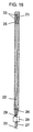
- Fig. 10 is a cross sectional view depicting a temperature detecting portion of the same temperature sensor.
- a reference numeral 21 represents a metal cylinder which is made of heat resistant stainless steel having an outer diameter of 3 mm and a thickness of 0.4 mm and provided with openings at the tip side and the hinder side.
- a long ceramic substrate 22 made of alumina having a thickness of 0.5 mm, a width of 2 mm and a length of 70 mm is placed in the metal cylinder 21.
- a tip side of the ceramic substrate 22 is provided with a film-like temperature detecting element 23 formed by a CVD method.
- the temperature detecting element 23 used in this exemplary embodiment was a thermistor made of an oxide-composite of Al, Cr and Fe, with a length of 2 mm and a width of 1.5 mm.
- the temperature detecting element 23 is connected on its surface with a pair of electrodes 24 in a pattern form for electrically detecting a resistance.
- the electrodes 24 in this exemplary embodiment were formed by printing and sintering platinum paste from the tip side to the hinder side of the ceramic substrate 22, with their width and pattern space arranged to be 0.5 mm each.
- the tip side of the ceramic substrate 22 is secured by covering an interior of the tip of the metal cylinder 21 with inorganic filler 25 which serves as a supporting means having a function of reducing stress.
- the inorganic filler 25 used here was a pasty form containing silica and Li 2 O, in addition to a chief ingredient of alumina, and it was placed in a such manner that the tip end of the ceramic substrate 22 locates within it.
- the hinder side of the ceramic substrate 22 was supported by adhering it to a hinder end of the metal cylinder 21 with a resilient body 26 composed of silicone which serves as a supporting means having a function of reducing stress.
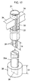
- Fig. 11 is a perspective view depicting an appearance of the same temperature sensor in a process of inserting the ceramic substrate 22 into terminals 27.
- terminals 27, each of which is made of stainless steel of 0.3 mm thick with a nickel-plated surface, and provided with a tip end in a cross sectional shape of letter U, are fixed to hinder ends of the electrodes 24 by way of inserting the ceramic substrate 22 into a space formed by the shape of letter U.
- terminals 27 were described as having a cross-sectional shape of letter U, they could be of a shape of the letter U with angled corners. A suitable shape may be chosen according to an ease of fabrication.
- the terminals 27 are secured at their hinder ends in a retainer 28 formed of glass fiber-reinforced resin.
- the terminals 27 and the retainer 28 were integrally formed by injection molding.
- Each terminal 27 is also provided at its middle portion with an expansion-and-contraction absorber 29 having a curved shape with a width of 0.3 mm.
- Each terminal 27 is connected with a lead wire 30 at its hinder end by welding.
- the welding was adopted in order to gain a sufficient strength against tension of the lead wire 30.
- Each terminal 27 is provided with a square-shaped notch 31 at a portion of the tip end.
- An electrical connection to the electrode 24 is attained by soldering the notched portion with solder 32 of high melting point.
- An enlarged cross sectional view of the connecting portion is shown in Fig. 12. Reliable connections can be realized between the terminals 27 and the electrodes 24 because of the notches 31, which provide for secure bonding of the solder 32 to the electrodes 24, and the nickel-plated surfaces of the terminals 27, which provide for secure bonding of the solder 32 to the terminals 27.
- Openings 33 are provided at four locations of the metal cylinder 21 corresponding with the temperature detecting element 23, and in a such manner that they locate symmetrically to one another.
- the openings 33 are sized 5 mm long by 1.7 mm wide, which is larger than an area (2 by 1.5 mm) of the temperature detecting element 23.
- a reference numeral 37 represents a nut attached to an outer periphery of the metal cylinder 21 for a purpose of mounting the temperature ceramic.
- Fig. 13 is an exploded front view depicting the ceramic substrate 22 provided with the temperature detecting element 23 and the electrodes 24, and the metal cylinder 21 provided with the openings 33.
- the ceramic substrate 22 is inserted into the metal cylinder 21 in a direction of an arrow shown in Fig. 13.
- substrate fixing jigs 34 made of Teflon are inserted through the openings 33 in a manner to hold a front and a back of the ceramic substrate 22 between them.
- Fig. 14 is a perspective view depicting an appearance in this process.
- the substrate fixing jigs 34 were made to have a cross sectional area of 3 mm long by 1.6 mm wide, which is smaller than the area (5 by 1.7 mm) of the openings 33, but larger than the area (2 by 1.5 mm) of the temperature detecting element 23.
- inorganic filler 25 is filled into a concavity 36 provided in an inorganic filler hardening jig 35 made of Teflon, as shown in a perspective view of Fig. 15.
- the concavity 36 was made to have a depth nearly equal to a dimension between a tip of the metal cylinder 21 and a tip end of the openings 33 (denoted as Lp in Fig. 15). Also, a diameter was made to be slightly greater than a diameter of the metal cylinder 21.
- the tip of the metal cylinder 21 is immersed into the concavity 36, while holding the ceramic substrate 22 with the substrate fixing jigs 34. This allows the inorganic filler 25 to enter into the tip portion of the metal cylinder 21 by an amount determined by the diameter and the depth of the concavity 36.
- the inorganic filler 25 is hardened under this condition at 150 °C in a constant temperature oven.
- the substrate fixing jigs 34 and the inorganic filler hardening jig 35 are removed after the above process.
- the both jigs 34 and 35 can be removed easily without adhesion of the inorganic filler 25, since they are made of Teflon.
- the substrate fixing jigs 34 and the inorganic filler hardening jig 35 can be made of metal for providing a quite equivalent effectiveness, if their surfaces are coated with Teflon.
- the above manufacturing method could make only the tip end of the ceramic substrate 22 secured to a generally center position of the metal cylinder 21, without causing the inorganic filler 25 to adhere on the temperature detecting element 23.
- Detection of a temperature was made electrically as a change in resistance value of the temperature detecting element 23 in response to the temperature.
- Ten pieces of prototype temperature sensor having the foregoing structure were built, and evaluated for a rate of yields. The result showed a substantial improvement in yields as compared to that of the prior art structure, as none of the sensors exhibited disconnection. This result is attributed to (a) fixation of the ceramic substrate 22 only at the tip end of the metal cylinder 21, (b) retaining the hinder end with the resilient body 26, and (c) additionally providing the expansion-and-contraction absorbers 29 in the terminals 27.
- the above structure eliminates stress to the ceramic substrate 22, since the expansion-and-contraction absorbers 29 absorb, through the resilient body 26, expansion and contraction of the ceramic substrate 22 due to a difference in coefficient of thermal expansion between the metal cylinder 21 and the ceramic substrate 22 with changes in temperature.
- the sensors provide a good resistance-to-temperature characteristic in the same degree as that of the prior art device. They also showed clearly of an extremely good reliability, as there was no disconnection as a result of an endurance test performed under a high temperature and vibrations. The sensors also attained an approximately 40 % of speedier response as compared to the prior art device according to a result of evaluation for responsivity.
- This improvement is attributed to the present structure, in which the temperature detecting element 23 is positioned in the metal cylinder 21, and the metal cylinder 21 is provided with the openings 33 at the tip thereof, whereas the temperature detecting element was housed and protected within a metal cap in prior art structure.
- the present structure thus transmits directly a change in temperature, which is otherwise transmitted through the cap, to the temperature detecting element 23.
- silicone to form the resilient body 26
- polyimide is effective in constituting a temperature sensor of a higher temperature application, since it is resistant to higher temperature than silicone.
- thermistor was used as the temperature detecting element 23 in the present exemplary embodiment, it could be platinum.
- the platinum element has an advantage of reducing the manufacturing process, because it can be formed together with the electrodes 24, although it has a lower rate of change in resistance to temperature than thermistor.
- a suitable type of the temperature detecting element 23 may be chosen according to an individual use application. In the case of using platinum, a precise measurement of resistance is required, since it has a low rate of change in resistance.
- the sensor can provide a change in resistance of only the temperature detecting element 23, if a four-wire method of measuring resistance is adopted by providing four electrodes 24, because the four-wire method cancels out a change in resistance of the electrodes 24 by the temperature of their own.
- the present exemplary embodiment could realize temperature sensors with high yield.
- a temperature sensor of a fourth exemplary embodiment of the present invention has many structural elements in common with that of the third exemplary embodiment, as shown in Fig. 16, same elements are assigned the same reference numerals and descriptions will be simplified.
- the present exemplary embodiment is characterized by employing inorganic filler 25 as a supporting means having a stress-reducing function to secure a ceramic substrate 22 to a metal cylinder 21 at a hinder end of openings 33, instead of securing a tip end of the ceramic substrate 22 with the inorganic filler 25.
- inorganic filler 25 as a supporting means having a stress-reducing function to secure a ceramic substrate 22 to a metal cylinder 21 at a hinder end of openings 33, instead of securing a tip end of the ceramic substrate 22 with the inorganic filler 25.
- Fig. 16 is a cross sectional view depicting a temperature detecting portion.
- the inorganic filler 25 is filled for approximately 2 mm thick from the hinder end of the openings 33, so that this portion secures the ceramic substrate 22 to the metal cylinder 21.
- the temperature detecting portion was fabricated with a method as described below.
- the ceramic substrate 22 is inserted into the metal cylinder 21, as shown in Fig. 13.
- substrate fixing jigs 34 made of Teflon are inserted through the openings 33 in a manner to hold a front and a back of the ceramic substrate 22 between them.
- Fig. 17 is a perspective view depicting an appearance in this process.
- the substrate fixing jigs 34 were made to have the same cross-sectional area as those of the third exemplary embodiment.
- an inorganic filler hardening jig 35a in a shape shown in Fig. 17 is inserted from a hinder end of the metal cylinder 21 into spaces between the metal cylinder 21 and a front and a back of the ceramic substrate 22.
- a length of the inorganic filler hardening jig 35a was arranged to be 2 mm shorter than a distance from the hinder end of the metal cylinder 21 to the hinder end of the openings 33.
- a base 38 of the inorganic filler hardening jig 35a was made to have a hole 39 in a size slightly larger than a cross sectional area of the ceramic substrate 22, and in a depth approximately equal to a length of a protruded portion (denoted as Lk in Fig. 17) from the hinder end of the ceramic substrate 22.
- the protruded portion of the ceramic substrate 22 is inserted into this hole 39. Because of a shape of the inorganic filler hardening jig 35a, which is not only thin but also long and narrow and intricate, it was made by a process of cuffing stainless steel into the shape, and coating with Teflon to form a film on its surface.
- Fig. 18 the inorganic filler hardening jig 35a is shown as has been inserted into the spaces between the metal cylinder 21 and a front and a back of the ceramic substrate 22. A portion of the metal cylinder 21 is cut away in the perspective view of Fig. 18 in order to make it more comprehensible.
- nozzles of dispensers 40 are inserted from both sides of the ceramic substrate 22 through gaps in the openings 33 as shown in Fig. 18.
- a predetermined amount of the inorganic filler 25 is then injected into spaces provided among the metal cylinder 21, the ceramic substrate 22, and the inorganic filler hardening jig 35a.
- the inorganic filler 25 is hardened under this condition at 150 °C in a constant temperature oven.
- the substrate fixing jigs 34 and the inorganic filler hardening jig 35a are removed after the above process.
- the both jigs 34 and 35a can be removed easily without adhesion of the inorganic filler 25, since they are made of Teflon or stainless steel with Teflon coated surfaces.
- the foregoing manufacturing method could fix the ceramic substrate 22 securely in the metal cylinder 21.
- the above manufacturing method takes a process of inserting the inorganic filler hardening jig 35a into the metal cylinder 21 after fixing the ceramic substrate 22 with the substrate fixing jigs 34, the process may be reversed to attain completely same fixation of the ceramic substrate 22.
- the temperature sensor manufactured as above exhibits high yield, good output performance and reliability in the same level as that of the third exemplary embodiment, and also realizes a fast response.
- a sensor of the third exemplary embodiment permits gases from the openings 33 into a direct contact with the resilient body 26 and allows corrosion if it is used for measuring temperature of corrosive gases or the like.
- the present exemplary embodiment in which the inorganic filler 25 is arranged at the hinder end of the openings 33, can make the sensor capable to take temperature measurement even in corrosive gases, since the inorganic filler 25 prevents the gases from entering into an interior of the sensor.
- the foregoing structure could realize temperature sensors with high yield.
- the present invention is able to provide a low-cost high-performance temperature sensor, without requiring use of expensive platinum wires for lead wires, with the structure including (a) a metal cylinder; (b) a ceramic substrate inserted in the metal cylinder, and provided with a temperature detecting element in a form of film and electrodes in a form of film for electrically tapping off an output of the temperature detecting element; (c) a supporting means having a function of reducing stress for supporting the ceramic substrate in the metal cylinder; and (d) a protective cap provided on one end of the metal cylinder for protecting the temperature detecting element provided on the ceramic substrate.
- the invention can also provide a temperature sensor with high yield, because the ceramic substrate is supported in the metal cylinder by the supporting means having a stress-reducing function, thereby reducing stress to an entire body of the ceramic substrate, and avoiding disconnection from occurring.
Landscapes
- Physics & Mathematics (AREA)
- Nonlinear Science (AREA)
- General Physics & Mathematics (AREA)
- Measuring Temperature Or Quantity Of Heat (AREA)
Applications Claiming Priority (5)
| Application Number | Priority Date | Filing Date | Title |
|---|---|---|---|
| JP10002005A JPH11201832A (ja) | 1998-01-08 | 1998-01-08 | 温度センサ |
| JP200598 | 1998-01-08 | ||
| JP10022886A JPH11218448A (ja) | 1998-02-04 | 1998-02-04 | 温度センサおよびその製造方法 |
| JP2288698 | 1998-02-04 | ||
| PCT/JP1999/000044 WO1999035475A1 (fr) | 1998-01-08 | 1999-01-08 | Capteur de temperature et procede de fabrication |
Publications (2)
| Publication Number | Publication Date |
|---|---|
| EP0965826A1 true EP0965826A1 (fr) | 1999-12-22 |
| EP0965826A4 EP0965826A4 (fr) | 2000-03-22 |
Family
ID=26335316
Family Applications (1)
| Application Number | Title | Priority Date | Filing Date |
|---|---|---|---|
| EP99900155A Withdrawn EP0965826A4 (fr) | 1998-01-08 | 1999-01-08 | Capteur de temperature et procede de fabrication |
Country Status (3)
| Country | Link |
|---|---|
| US (1) | US6297723B1 (fr) |
| EP (1) | EP0965826A4 (fr) |
| WO (1) | WO1999035475A1 (fr) |
Cited By (1)
| Publication number | Priority date | Publication date | Assignee | Title |
|---|---|---|---|---|
| EP3553481A4 (fr) * | 2018-02-13 | 2019-11-20 | Shibaura Electronics Co., Ltd. | Capteur de température, élément de capteur et procédé de fabrication d'un capteur de température |
Families Citing this family (27)
| Publication number | Priority date | Publication date | Assignee | Title |
|---|---|---|---|---|
| DE10016415A1 (de) * | 2000-04-01 | 2001-10-11 | Bosch Gmbh Robert | Sensorelement, insbesondere Temperaturfühler |
| DE10031124C2 (de) * | 2000-06-30 | 2002-05-16 | Heraeus Electro Nite Int | Sensor zur Temperaturerfassung eines Fluids |
| DE10033589A1 (de) * | 2000-07-11 | 2002-01-31 | Bosch Gmbh Robert | Mikrostrukturierter Thermosensor |
| JP2003234203A (ja) * | 2002-02-07 | 2003-08-22 | Denso Corp | 温度センサの製造方法 |
| US7121722B2 (en) * | 2003-05-02 | 2006-10-17 | Ngk Spark Plug Co., Ltd. | Temperature sensor |
| US7915994B2 (en) * | 2003-11-13 | 2011-03-29 | Harco Laboratories, Inc. | Thermal variable resistance device with protective sheath |
| US20060037394A1 (en) * | 2004-08-20 | 2006-02-23 | Honeywell International, Inc. | High temperature sensor sleeve |
| US7545272B2 (en) | 2005-02-08 | 2009-06-09 | Therasense, Inc. | RF tag on test strips, test strip vials and boxes |
| US7316507B2 (en) | 2005-11-03 | 2008-01-08 | Covidien Ag | Electronic thermometer with flex circuit location |
| US7748898B2 (en) * | 2007-02-27 | 2010-07-06 | Denso Corporation | Temperature sensor and method of producing the temperature sensor |
| US7749170B2 (en) | 2007-05-22 | 2010-07-06 | Tyco Healthcare Group Lp | Multiple configurable electronic thermometer |
| US7802472B1 (en) * | 2007-08-21 | 2010-09-28 | Fluke Corporation | Ruggedized sensor probe |
| US8496377B2 (en) * | 2007-12-31 | 2013-07-30 | Covidien Lp | Thermometer having molded probe component |
| DE102008029192A1 (de) * | 2008-03-13 | 2009-09-24 | Epcos Ag | Fühler zum Erfassen einer physikalischen Größe und Verfahren zur Herstellung des Fühlers |
| DE102008015359A1 (de) * | 2008-03-20 | 2009-09-24 | Endress + Hauser Flowtec Ag | Temperatursensor und Verfahren zu dessen Herstellung |
| DE102009028848A1 (de) * | 2009-08-24 | 2011-03-03 | Endress + Hauser Flowtec Ag | Aufbau und Herstellungsverfahrens eines Sensors eines thermischen Durchflussmessgeräts |
| DE102009028850A1 (de) * | 2009-08-24 | 2011-03-03 | Endress + Hauser Flowtec Ag | Herstellungsverfahren eines Sensors eines thermischen Durchflussmessgeräts |
| FR2958397B1 (fr) * | 2010-03-30 | 2012-12-14 | Sc2N Sa | Capteur de temperature |
| US8523430B2 (en) * | 2010-07-28 | 2013-09-03 | Lattron Co. Ltd. | Ultra thin temperature sensor device |
| DE102011009754A1 (de) * | 2011-01-28 | 2012-08-02 | Heraeus Sensor Technology Gmbh | Strömungssensoren mit Stromdurchführung im Deckel und Sensorspitze als Zwischenprodukt |
| DE102011103331B3 (de) * | 2011-05-27 | 2012-11-29 | Inor Process Ab | Temperaturfühler für ein Kontaktthermometer |
| DE102012110845A1 (de) * | 2012-11-12 | 2014-05-15 | Epcos Ag | Temperaturfühler und Verfahren zur Herstellung eines Temperaturfühlers |
| WO2018146776A1 (fr) * | 2017-02-09 | 2018-08-16 | 株式会社芝浦電子 | Capteur de température |
| US11460353B2 (en) * | 2017-05-01 | 2022-10-04 | Semitec Corporation | Temperature sensor and device equipped with temperature sensor |
| JP7151369B2 (ja) * | 2018-10-22 | 2022-10-12 | 株式会社デンソー | 温度センサ |
| US12487134B2 (en) * | 2021-02-05 | 2025-12-02 | Sensata Technologies, Inc. | System and method for improving temperature detectors using expansion/contraction devices |
| USD1105604S1 (en) * | 2024-03-21 | 2025-12-09 | Japonesque, Llc | Dermaplaner |
Family Cites Families (18)
| Publication number | Priority date | Publication date | Assignee | Title |
|---|---|---|---|---|
| US2599550A (en) * | 1949-04-27 | 1952-06-10 | Fraser Robert | Fluxmeter and probe therefor |
| US3832668A (en) * | 1972-03-31 | 1974-08-27 | Westinghouse Electric Corp | Silicon carbide junction thermistor |
| JPS5051377A (fr) | 1973-09-04 | 1975-05-08 | ||
| JPS5886428A (ja) | 1981-11-19 | 1983-05-24 | Matsushita Electric Ind Co Ltd | 金属管封入型温度センサの製造法 |
| US4442420A (en) * | 1982-09-30 | 1984-04-10 | Ford Motor Company | Partial pressure of oxygen sensor-II |
| JPS6035501A (ja) | 1983-08-08 | 1985-02-23 | 三井金属鉱業株式会社 | リ−ド線付き電子回路素子およびその製造方法 |
| JPS60131432A (ja) | 1983-12-20 | 1985-07-13 | Terumo Corp | 電子体温計の製造方法 |
| EP0471316B1 (fr) * | 1990-08-17 | 1996-09-18 | Sensycon Gesellschaft Für Industrielle Sensorsysteme Und Prozessleittechnik Mbh | Détecteur pour un débitmètre thermique |
| JPH04282427A (ja) | 1991-03-12 | 1992-10-07 | Hitachi Ltd | 温度検出センサー |
| JP3203803B2 (ja) * | 1992-09-01 | 2001-08-27 | 株式会社デンソー | サーミスタ式温度センサ |
| DE4237224C2 (de) * | 1992-11-04 | 1999-11-04 | Bosch Gmbh Robert | Temperaturfühler |
| JP3175890B2 (ja) * | 1993-12-27 | 2001-06-11 | 日本碍子株式会社 | 温度センサ |
| JP3030213B2 (ja) * | 1994-08-17 | 2000-04-10 | 旭テクノグラス株式会社 | 温度計測装置 |
| CN1052299C (zh) | 1995-05-11 | 2000-05-10 | 松下电器产业株式会社 | 温度传感元件和装有它的温度传感器及温度传感元件的制造方法 |
| JPH09126910A (ja) | 1995-11-06 | 1997-05-16 | Matsushita Electric Ind Co Ltd | 温度検出装置 |
| DE19542516C1 (de) * | 1995-11-15 | 1997-04-17 | Heraeus Sensor Gmbh | Temperatur-Sensor |
| JP3000910B2 (ja) | 1996-01-08 | 2000-01-17 | 松下電器産業株式会社 | 温度検出装置 |
| US5726624A (en) * | 1996-07-01 | 1998-03-10 | Honeywell Inc. | Temperature sensor with internal rigid substrate |
-
1999
- 1999-01-08 EP EP99900155A patent/EP0965826A4/fr not_active Withdrawn
- 1999-01-08 WO PCT/JP1999/000044 patent/WO1999035475A1/fr not_active Ceased
- 1999-01-08 US US09/380,952 patent/US6297723B1/en not_active Expired - Fee Related
Non-Patent Citations (2)
| Title |
|---|
| No further relevant documents disclosed * |
| See also references of WO9935475A1 * |
Cited By (2)
| Publication number | Priority date | Publication date | Assignee | Title |
|---|---|---|---|---|
| EP3553481A4 (fr) * | 2018-02-13 | 2019-11-20 | Shibaura Electronics Co., Ltd. | Capteur de température, élément de capteur et procédé de fabrication d'un capteur de température |
| US11428584B2 (en) | 2018-02-13 | 2022-08-30 | Shibaura Electronics Co., Ltd. | Temperature sensor, sensor element and manufacturing method of temperature sensor |
Also Published As
| Publication number | Publication date |
|---|---|
| US6297723B1 (en) | 2001-10-02 |
| EP0965826A4 (fr) | 2000-03-22 |
| WO1999035475A1 (fr) | 1999-07-15 |
Similar Documents
| Publication | Publication Date | Title |
|---|---|---|
| US6297723B1 (en) | Temperature sensor and method of manufacturing the same | |
| US6899457B2 (en) | Thermistor temperature sensor | |
| US20020135455A1 (en) | Temperature sensor | |
| US4636293A (en) | Internally heated oxygen sensor, particularly for use with internal combustion engines | |
| JP2002289407A (ja) | 温度センサおよびその製造方法 | |
| KR20080008995A (ko) | 내연기관의 배기가스 시스템에 사용되는 저항 온도계용온도 센서 | |
| JPH04319634A (ja) | 温度センサ | |
| JP6608088B1 (ja) | 温度センサ | |
| JP2019095355A (ja) | 温度センサ | |
| JPH05501012A (ja) | 内燃機関の燃焼室内の圧力を検出するための圧力センサ | |
| US6354134B1 (en) | Oxygen sensing element used in a oxygen sensor | |
| US6647779B2 (en) | Temperature sensing resistance element and thermal flow sensor using same | |
| JP2006234632A (ja) | 温度センサ | |
| US5652443A (en) | Sensor having a micro-bridge heater | |
| EP0824258B1 (fr) | Structure de dispositif électronique | |
| US4596132A (en) | Gas component detecting plug | |
| JP4269512B2 (ja) | 温度センサ | |
| JP2515067Y2 (ja) | サーミスタ温度センサ | |
| JPH11190716A (ja) | ガスセンサ | |
| JPH08219904A (ja) | サーミスタ式表面温度センサ | |
| JP4059222B2 (ja) | 温度センサ及び温度センサの製造方法 | |
| US20250123153A1 (en) | Temperature sensor and rotary electric machine | |
| JP2005106685A (ja) | ガスセンサ | |
| JP3420190B2 (ja) | 複合センサのモールドユニット部品の製造方法 | |
| CN112912703A (zh) | 温度传感器 |
Legal Events
| Date | Code | Title | Description |
|---|---|---|---|
| PUAI | Public reference made under article 153(3) epc to a published international application that has entered the european phase |
Free format text: ORIGINAL CODE: 0009012 |
|
| AK | Designated contracting states |
Kind code of ref document: A1 Designated state(s): DE FR GB |
|
| RIN1 | Information on inventor provided before grant (corrected) |
Inventor name: SAITOU, KIYOSHI Inventor name: MATSUBARA, KATSUNORI Inventor name: TAMAI, TAKASHI Inventor name: SHOJI, RIHITO |
|
| 17P | Request for examination filed |
Effective date: 19991222 |
|
| A4 | Supplementary search report drawn up and despatched |
Effective date: 20000204 |
|
| AK | Designated contracting states |
Kind code of ref document: A4 Designated state(s): DE FR GB |
|
| RIC1 | Information provided on ipc code assigned before grant |
Free format text: 7G 01K 7/22 A, 7G 01K 7/18 B |
|
| 17Q | First examination report despatched |
Effective date: 20071106 |
|
| STAA | Information on the status of an ep patent application or granted ep patent |
Free format text: STATUS: THE APPLICATION IS DEEMED TO BE WITHDRAWN |
|
| 18D | Application deemed to be withdrawn |
Effective date: 20080318 |