EP0967400A2 - Dispositif de régulation pour un système hydraulique - Google Patents
Dispositif de régulation pour un système hydraulique Download PDFInfo
- Publication number
- EP0967400A2 EP0967400A2 EP98122634A EP98122634A EP0967400A2 EP 0967400 A2 EP0967400 A2 EP 0967400A2 EP 98122634 A EP98122634 A EP 98122634A EP 98122634 A EP98122634 A EP 98122634A EP 0967400 A2 EP0967400 A2 EP 0967400A2
- Authority
- EP
- European Patent Office
- Prior art keywords
- pressure
- control arrangement
- control
- arrangement according
- hydraulic
- Prior art date
- Legal status (The legal status is an assumption and is not a legal conclusion. Google has not performed a legal analysis and makes no representation as to the accuracy of the status listed.)
- Granted
Links
Images


Classifications
-
- F—MECHANICAL ENGINEERING; LIGHTING; HEATING; WEAPONS; BLASTING
- F15—FLUID-PRESSURE ACTUATORS; HYDRAULICS OR PNEUMATICS IN GENERAL
- F15B—SYSTEMS ACTING BY MEANS OF FLUIDS IN GENERAL; FLUID-PRESSURE ACTUATORS, e.g. SERVOMOTORS; DETAILS OF FLUID-PRESSURE SYSTEMS, NOT OTHERWISE PROVIDED FOR
- F15B11/00—Servomotor systems without provision for follow-up action; Circuits therefor
- F15B11/02—Systems essentially incorporating special features for controlling the speed or actuating force of an output member
- F15B11/028—Systems essentially incorporating special features for controlling the speed or actuating force of an output member for controlling the actuating force
-
- F—MECHANICAL ENGINEERING; LIGHTING; HEATING; WEAPONS; BLASTING
- F15—FLUID-PRESSURE ACTUATORS; HYDRAULICS OR PNEUMATICS IN GENERAL
- F15B—SYSTEMS ACTING BY MEANS OF FLUIDS IN GENERAL; FLUID-PRESSURE ACTUATORS, e.g. SERVOMOTORS; DETAILS OF FLUID-PRESSURE SYSTEMS, NOT OTHERWISE PROVIDED FOR
- F15B21/00—Common features of fluid actuator systems; Fluid-pressure actuator systems or details thereof, not covered by any other group of this subclass
- F15B21/08—Servomotor systems incorporating electrically operated control means
- F15B21/085—Servomotor systems incorporating electrically operated control means using a data bus, e.g. "CANBUS"
-
- G—PHYSICS
- G05—CONTROLLING; REGULATING
- G05D—SYSTEMS FOR CONTROLLING OR REGULATING NON-ELECTRIC VARIABLES
- G05D27/00—Simultaneous control of variables covered by two or more of main groups G05D1/00 - G05D25/00
- G05D27/02—Simultaneous control of variables covered by two or more of main groups G05D1/00 - G05D25/00 characterised by the use of electric means
-
- F—MECHANICAL ENGINEERING; LIGHTING; HEATING; WEAPONS; BLASTING
- F15—FLUID-PRESSURE ACTUATORS; HYDRAULICS OR PNEUMATICS IN GENERAL
- F15B—SYSTEMS ACTING BY MEANS OF FLUIDS IN GENERAL; FLUID-PRESSURE ACTUATORS, e.g. SERVOMOTORS; DETAILS OF FLUID-PRESSURE SYSTEMS, NOT OTHERWISE PROVIDED FOR
- F15B2211/00—Circuits for servomotor systems
- F15B2211/20—Fluid pressure source, e.g. accumulator or variable axial piston pump
- F15B2211/205—Systems with pumps
- F15B2211/2053—Type of pump
- F15B2211/20538—Type of pump constant capacity
-
- F—MECHANICAL ENGINEERING; LIGHTING; HEATING; WEAPONS; BLASTING
- F15—FLUID-PRESSURE ACTUATORS; HYDRAULICS OR PNEUMATICS IN GENERAL
- F15B—SYSTEMS ACTING BY MEANS OF FLUIDS IN GENERAL; FLUID-PRESSURE ACTUATORS, e.g. SERVOMOTORS; DETAILS OF FLUID-PRESSURE SYSTEMS, NOT OTHERWISE PROVIDED FOR
- F15B2211/00—Circuits for servomotor systems
- F15B2211/20—Fluid pressure source, e.g. accumulator or variable axial piston pump
- F15B2211/205—Systems with pumps
- F15B2211/2053—Type of pump
- F15B2211/20546—Type of pump variable capacity
- F15B2211/20553—Type of pump variable capacity with pilot circuit, e.g. for controlling a swash plate
-
- F—MECHANICAL ENGINEERING; LIGHTING; HEATING; WEAPONS; BLASTING
- F15—FLUID-PRESSURE ACTUATORS; HYDRAULICS OR PNEUMATICS IN GENERAL
- F15B—SYSTEMS ACTING BY MEANS OF FLUIDS IN GENERAL; FLUID-PRESSURE ACTUATORS, e.g. SERVOMOTORS; DETAILS OF FLUID-PRESSURE SYSTEMS, NOT OTHERWISE PROVIDED FOR
- F15B2211/00—Circuits for servomotor systems
- F15B2211/20—Fluid pressure source, e.g. accumulator or variable axial piston pump
- F15B2211/205—Systems with pumps
- F15B2211/2053—Type of pump
- F15B2211/20569—Type of pump capable of working as pump and motor
-
- F—MECHANICAL ENGINEERING; LIGHTING; HEATING; WEAPONS; BLASTING
- F15—FLUID-PRESSURE ACTUATORS; HYDRAULICS OR PNEUMATICS IN GENERAL
- F15B—SYSTEMS ACTING BY MEANS OF FLUIDS IN GENERAL; FLUID-PRESSURE ACTUATORS, e.g. SERVOMOTORS; DETAILS OF FLUID-PRESSURE SYSTEMS, NOT OTHERWISE PROVIDED FOR
- F15B2211/00—Circuits for servomotor systems
- F15B2211/30—Directional control
- F15B2211/305—Directional control characterised by the type of valves
- F15B2211/30525—Directional control valves, e.g. 4/3-directional control valve
-
- F—MECHANICAL ENGINEERING; LIGHTING; HEATING; WEAPONS; BLASTING
- F15—FLUID-PRESSURE ACTUATORS; HYDRAULICS OR PNEUMATICS IN GENERAL
- F15B—SYSTEMS ACTING BY MEANS OF FLUIDS IN GENERAL; FLUID-PRESSURE ACTUATORS, e.g. SERVOMOTORS; DETAILS OF FLUID-PRESSURE SYSTEMS, NOT OTHERWISE PROVIDED FOR
- F15B2211/00—Circuits for servomotor systems
- F15B2211/30—Directional control
- F15B2211/31—Directional control characterised by the positions of the valve element
- F15B2211/3122—Special positions other than the pump port being connected to working ports or the working ports being connected to the return line
- F15B2211/3127—Floating position connecting the working ports and the return line
-
- F—MECHANICAL ENGINEERING; LIGHTING; HEATING; WEAPONS; BLASTING
- F15—FLUID-PRESSURE ACTUATORS; HYDRAULICS OR PNEUMATICS IN GENERAL
- F15B—SYSTEMS ACTING BY MEANS OF FLUIDS IN GENERAL; FLUID-PRESSURE ACTUATORS, e.g. SERVOMOTORS; DETAILS OF FLUID-PRESSURE SYSTEMS, NOT OTHERWISE PROVIDED FOR
- F15B2211/00—Circuits for servomotor systems
- F15B2211/30—Directional control
- F15B2211/31—Directional control characterised by the positions of the valve element
- F15B2211/3144—Directional control characterised by the positions of the valve element the positions being continuously variable, e.g. as realised by proportional valves
-
- F—MECHANICAL ENGINEERING; LIGHTING; HEATING; WEAPONS; BLASTING
- F15—FLUID-PRESSURE ACTUATORS; HYDRAULICS OR PNEUMATICS IN GENERAL
- F15B—SYSTEMS ACTING BY MEANS OF FLUIDS IN GENERAL; FLUID-PRESSURE ACTUATORS, e.g. SERVOMOTORS; DETAILS OF FLUID-PRESSURE SYSTEMS, NOT OTHERWISE PROVIDED FOR
- F15B2211/00—Circuits for servomotor systems
- F15B2211/30—Directional control
- F15B2211/32—Directional control characterised by the type of actuation
- F15B2211/327—Directional control characterised by the type of actuation electrically or electronically
-
- F—MECHANICAL ENGINEERING; LIGHTING; HEATING; WEAPONS; BLASTING
- F15—FLUID-PRESSURE ACTUATORS; HYDRAULICS OR PNEUMATICS IN GENERAL
- F15B—SYSTEMS ACTING BY MEANS OF FLUIDS IN GENERAL; FLUID-PRESSURE ACTUATORS, e.g. SERVOMOTORS; DETAILS OF FLUID-PRESSURE SYSTEMS, NOT OTHERWISE PROVIDED FOR
- F15B2211/00—Circuits for servomotor systems
- F15B2211/60—Circuit components or control therefor
- F15B2211/63—Electronic controllers
- F15B2211/6303—Electronic controllers using input signals
- F15B2211/6306—Electronic controllers using input signals representing a pressure
- F15B2211/6313—Electronic controllers using input signals representing a pressure the pressure being a load pressure
-
- F—MECHANICAL ENGINEERING; LIGHTING; HEATING; WEAPONS; BLASTING
- F15—FLUID-PRESSURE ACTUATORS; HYDRAULICS OR PNEUMATICS IN GENERAL
- F15B—SYSTEMS ACTING BY MEANS OF FLUIDS IN GENERAL; FLUID-PRESSURE ACTUATORS, e.g. SERVOMOTORS; DETAILS OF FLUID-PRESSURE SYSTEMS, NOT OTHERWISE PROVIDED FOR
- F15B2211/00—Circuits for servomotor systems
- F15B2211/60—Circuit components or control therefor
- F15B2211/63—Electronic controllers
- F15B2211/6303—Electronic controllers using input signals
- F15B2211/6346—Electronic controllers using input signals representing a state of input means, e.g. joystick position
Definitions
- the invention relates to a control arrangement for a hydraulic System according to the type of the main claim.
- Such a control arrangement is already known from DE 44 10 719 A1 known, in particular the pressure and other sizes in a hydraulic device, here an adjusting element for a pump, measured and specified the control arrangement can be influenced. This influencing takes place in a manner known per se with one of the hydraulic valve upstream of the hydraulic device, the valve spool, for example, electromagnetic is adjusted.
- the control arrangement has a digital one Bus connection for setting the controller and for online transmission of information from and to the device.
- the control arrangement also has at least one Device for converting the measured analog input signals into a digital one suitable for the microcomputer Shape.
- the setpoints for pressure and volume flow of the hydraulic system can be easily in analog form, digitally converted or after switching alternatively also in digital form through the bus system the control arrangement are transferred.
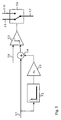
- the control arrangement has a switching device, which is the actual pressure value and derived from it Sizes monitored, and when a preset is exceeded Threshold values switch from the current to a preset setpoint for the pressure and / or causes the volume flow within one controller cycle.
- the transition of the setpoints can be abrupt or in one another form.
- the monitoring device can, for example, be on-line through the bus connection or be turned off.
- the switching device is particularly advantageous Way a weighted pressure gradient. From the actual value signal of the pressure, according to one embodiment a differentiator and a downstream amplifier the pressure gradient weighted by the factor is formed. This signal becomes in a subsequent adder added to the actual pressure value. A downstream comparator compares this signal with a threshold value. At If the threshold is exceeded, the setpoint of the Pressure by means of a switch from one value to one new value switched.
- the switching device formed such that when a Trigger signals a switch from the current to one preset setpoint for pressure and / or volume flow is effected within a controller cycle.
- the transition The setpoints can also be abrupt or in one another form.
- the trigger signal is from Sensors outside the control device from measured variables generated by comparison with a threshold and to the Control device directed.
- the sensors of this embodiment are bus participants and generate a trigger signal in the form of information using the bus protocol directly via the bus system is sent to the control device.
- the aforementioned The threshold is set using the bus protocol before the start control to the sensors.
- the sensors generate the trigger signal as binary signal with its switching edge in the microprocessor in the control device the switchover immediately triggers.
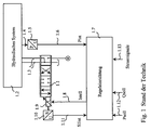
- the exemplary embodiment according to FIG. 1 is a control arrangement shown, for example for the control of a hydraulic Actuating cylinder for an injection cylinder in one Plastic injection molding machine can be used.
- a hydraulic Actuating cylinder for an injection cylinder in one Plastic injection molding machine can be used.
- the injection speed must guarantee of the liquid plastic, the reprint and the Back pressure during the casting process even with partial Cooling of the casting compound can be regulated.
- a directional valve 1.1 is inserted into the volume flow of the hydraulic fluid for a hydraulic system 1.2, for example as described above, and supplies this system 1.2 with a variable volume of the hydraulic fluid via two lines 1.3.
- the hydraulic system is a drive for an actuator.
- a pressure 1.4 is measured in the drive, which is set at a suitable point behind the valve 1.1. After a P / U converter 1.5, the measured pressure becomes the input signal P ist or 1.6 for a control device 1.7.
- a variable current I stell is led via a line 1.8 to an electromagnet 1.9, with which the position of a valve slide for the directional control valve 1.1 is changed and thus closes the control loop for pressure control.
- the position of this slide valve is controlled by the position of the valve spool measured is an S / U converter 1:10 to another input signal S1 and is fed via a line 11.1 the regulating device 1.7.
- the volume flow of the valve 1.1 is limited to a predetermined value for pressure control in the hydraulic system 1.2.
- the controller 1.7 receives this command values for pressure P soll and the volume flow Q to the hydraulic fluid via lines 12.1 and 13.1 further control signals for various operating states of the control device.
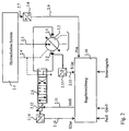
- a hydraulic system 2.1 is supplied with the hydraulic fluid by a variable displacement pump 2.2 via the connection 2.3, with a drive that is comparable to the embodiment according to FIG.
- the variable displacement pump 2.2 can be, for example, a radial piston pump as described in the prior art DE 44 10 719 A1 mentioned at the beginning.
- a return 2.4 there is still a leak oil connection.
- the delivery rate of the pump 2.2 is changed by means of an adjusting piston 2.5 by a control valve 2.6.
- the supply pressure 2.7 is measured at a suitable point and, after conversion with a P / U converter 2.8, the input signal P is fed via 2.9 to the control device 2.10.
- the output variable of this control device 2.10 is a variable current I stell , which adjusts the position of the valve slide in valve 2.6 via 2.11 by means of an electromagnet 2.12 and closes the control loop via the hydraulic lines to the adjusting piston 2.5 of the pump 2.2.
- the position of the adjustment of the adjusting piston 2.5 in the pump 2.2 and the valve slide in the valve 2.6 are measured and returned to the control device 2.10 via S / U converters 2.13 and 2.14. They provide further input signals S1 is via 2.15 and S2 is via 2.16 of the control device 2.10.
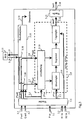
- FIG 3 is a block diagram of a control device shown as a control device 1.7 according to the figure 1 or 2.10 can be carried out according to Figure 2.
- control devices such as mentioned at the beginning, with one or more microprocessors can be equipped with signal processing and control in function modules with a predetermined Run the arithmetic program.
- the control of the function modules in the circuit 3.9 according to FIG. 3 is carried out by a known real-time operating system 3.10 of the microprocessors, which transmits the necessary control data 3.11 to all function modules.
- the operating system controls the timing for the cyclical calculation of a digital output signal I * alternate at point 3.12 on the input signals at 3.1 to 3.3 in the control clock.
- the digital output signal is brought by a corresponding converter 3.13 into a suitable current I * stell 3.14 for adjusting the magnet 1.9 according to the embodiment according to FIG. 1 or the magnet 2.12 according to the embodiment according to FIG.
- FIG. 3 also shows one for itself Known bus system 3.15 for data or signal transmission from and to the microprocessors not shown here shown schematically.
- the input signals instead of the conversion analog / digital directly in digital form through the bus system to transmit to the control device.
- the digital signals 3.5 to 3.8 are replaced by those from the input channel 3.16 data transmitted by the bus system.
- the measured signals are converted then outside the control device.
- the usage of a bus system brings advantages among other things in the simplified installation technology.
- the fieldbus systems known per se which can be used here and mentioned at the outset, generally do not achieve the high transmission speed for hydraulic pressure controls in order to transmit the measured actual values in the required controller cycle. Therefore, in the illustrated exemplary embodiments, the time-critical signals P ist , S1 ist , S2 is analog at the inputs 3.1, 3.2 via the converter and the time-uncritical signals P * soll and Q * soll on the connections 3.7, 3.8 and the control data 3.11 of the operating system 3.10 digitally via the input channel 3.16, ie transmitted via the bus system 3.15.
- the digital actual values P * ist an 3.5 present in the control device according to FIG. 3 can be transmitted from the operating system 3.10 via the output channel 3.17 of the bus system 3.15 to a higher-level control. If the operation of this control device is to take place alternatively with analog or digital input signals, it is possible for the operating system 3.10 to switch the signal paths with a suitable device 3.18.
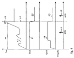
- the time profile 4.2 of the pressure value P ist according to FIG. 4 corresponds to the profile of the digital signal P * ist at 3.5 in the control device according to FIG. 3, the updated value following the actual value in the controller cycle.
- the actual pressure value P * is available via the output channel 3.17 for the bus system 3.15.
- the comparatively slow transmission speed of the bus system 3.15 makes it difficult to determine the exact changeover time.
- the alternative external measurement of the actual pressure P * and set the reference value P * to 3.15 over the bus system makes it difficult for the same reason the start of the exact timing of the switching.
- this disadvantage is eliminated in that the current actual pressure value P * ist at 3.5 is fed to a switching device 3.19 in the control device. If a threshold value is exceeded, the system switches over to the new pressure setpoint and / or volume flow in the same control cycle.
- the control data for the weighting factor, the threshold value and the new setpoints are transmitted before the start of the injection phase of the injection molding machine by means of the bus system 3.15.
- the function of the switchover device 3.19 corresponds to that of the switchover device shown in FIG. 5 and can be switched on or off via the bus system 3.15 by means of control data customary here.
- FIG. 4 A signal curve of the values in the control arrangement for an injection molding machine is recorded in FIG.
- the volume flow setpoint Q should be switched to a new value 6.5.
- the setpoint values can be changed abruptly or in another transition form (for example in the form of a ramp).
- the time of switching on the dashed timeline 6.6 can be different on the hydraulic system Measured variables are determined, which are detected by sensors and implemented (e.g. position of the feed cylinder of the Injection molding machine or the internal pressure in the injection mold). The switchover to the new setpoints takes place here by a trigger signal 6.7 to the one described above Control device.
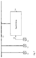
- FIG. 7 shows a circuit for the generation according to the invention from the switch.
- the trigger signal 6.7 is used by the sensors 7.1 for the position of the feed cylinder and 7.2 for the mold pressure or from other, not shown here Sensors generated and directly via a bus system 7.3 transmitted to a control device 7.4. The remaining connections the control device 7.4 are here for maintenance not drawn for clarity.
- the sensors 7.1 and 7.2 have a comparator that the measured signals with a via the bus system 7.3 programmed threshold value compares. If exceeded the sensors send a control word of this threshold value or a comparable information with the bus protocol to the control device 7.4.
- the control word is in front the beginning of the regulation between the bus participants sensor 7.1, 7.2 and control device 7.4.
- the control device resolves immediately upon receipt of the control word the switch off.
- the response time of the bus system 7.3 between reaching the threshold and the reception of the control word is not fast enough to switch the pressure P should be. This is possible, for example, when switching over with the sensor 7.2 for the internal mold pressure.
- the trigger signal is given to the control device 7.4 by another sensor 7.5 as a jump-shaped binary signal 7.6, bypassing the bus system 7.3.
- the signal may in this case via an input port of the microprocessor in the control device 7.4 immediately the pressure switch P is to read out.
- the response time of the bus system 7.3 is thereby switched off.
- FIG. 8 shows the bus-compliant signal processing during the switchover in the form of a flowchart.
- the program for controlling the microcomputer in control device 7.4 works with independent tasks, each of which is called by an interrupt.
- the bus transmission is shown in flow diagram 8.1; it effects an evaluation of the respective telegram in a branch 8.2.
- the task transfer runs according to flow chart 8.1.
- the trigger signal 6.7 can be processed by the tasks according to the flow diagram 8.5, which processes the input port. After determining the port number in query 8.6, the branch with the statement TRUE "the trigger signal 6.7 is stored in the program section 8.7 in the same register as in task 8.1. The task then runs to the end.
- control word and the register are queried for each control cycle in the task according to flow chart 8.8, in which the internal computer clock is called. If the switchover is activated, the answer to query 8.9 TRUE "and if the register with trigger signal 6.7 is also set, query 8.10 decides TRUE ". Then switch the program part 11.8 the set points P and Q is intended to. In all FALSE "In accordance with flow chart 8.8, the program runs past the setpoint switchover described above. The trigger signal 6.7 in the register must then be reset at a suitable point in the program for the next switchover.
Landscapes
- Engineering & Computer Science (AREA)
- Physics & Mathematics (AREA)
- Fluid Mechanics (AREA)
- Mechanical Engineering (AREA)
- General Engineering & Computer Science (AREA)
- Analytical Chemistry (AREA)
- Chemical & Material Sciences (AREA)
- General Physics & Mathematics (AREA)
- Automation & Control Theory (AREA)
- Injection Moulding Of Plastics Or The Like (AREA)
- Vehicle Body Suspensions (AREA)
- Fluid-Pressure Circuits (AREA)
- Control Of Transmission Device (AREA)
- Feedback Control In General (AREA)
Applications Claiming Priority (2)
| Application Number | Priority Date | Filing Date | Title |
|---|---|---|---|
| DE19828752 | 1998-06-27 | ||
| DE19828752A DE19828752A1 (de) | 1998-06-27 | 1998-06-27 | Regelanordnung für ein hydraulisches System |
Publications (3)
| Publication Number | Publication Date |
|---|---|
| EP0967400A2 true EP0967400A2 (fr) | 1999-12-29 |
| EP0967400A3 EP0967400A3 (fr) | 2001-01-24 |
| EP0967400B1 EP0967400B1 (fr) | 2004-02-18 |
Family
ID=7872242
Family Applications (1)
| Application Number | Title | Priority Date | Filing Date |
|---|---|---|---|
| EP98122634A Expired - Lifetime EP0967400B1 (fr) | 1998-06-27 | 1998-11-27 | Dispositif de régulation pour un système hydraulique |
Country Status (3)
| Country | Link |
|---|---|
| EP (1) | EP0967400B1 (fr) |
| AT (1) | ATE259941T1 (fr) |
| DE (2) | DE19828752A1 (fr) |
Cited By (2)
| Publication number | Priority date | Publication date | Assignee | Title |
|---|---|---|---|---|
| FR3128254A1 (fr) * | 2021-10-15 | 2023-04-21 | Robert Bosch Gmbh | Circuit hydraulique équipé d’un système de commande d’un composant hydraulique |
| DE102023109729A1 (de) | 2022-04-29 | 2023-11-02 | Engel Austria Gmbh | Hydrauliksystem für eine Formgebungsmaschine |
Families Citing this family (6)
| Publication number | Priority date | Publication date | Assignee | Title |
|---|---|---|---|---|
| DE10060285A1 (de) | 2000-12-05 | 2002-06-06 | Bosch Gmbh Robert | Verfahren zum Betrieb einer Regelanordnung für ein hydraulisches System |
| US7441404B2 (en) | 2004-11-30 | 2008-10-28 | Caterpillar Inc. | Configurable hydraulic control system |
| US7302797B2 (en) | 2005-05-31 | 2007-12-04 | Caterpillar Inc. | Hydraulic system having a post-pressure compensator |
| US7194856B2 (en) | 2005-05-31 | 2007-03-27 | Caterpillar Inc | Hydraulic system having IMV ride control configuration |
| RU2477876C1 (ru) * | 2012-04-16 | 2013-03-20 | Федеральное государственное бюджетное образовательное учреждение высшего профессионального образования "Тульский государственный университет" (ТулГУ) | Устройство контроля параметров условий труда |
| RU2643109C1 (ru) * | 2017-04-26 | 2018-01-30 | Федеральное государственное бюджетное образовательное учреждение высшего образования "Тульский государственный университет" (ТулГУ) | Устройство дистанционного контроля параметров условий труда с коррекцией по температуре |
Family Cites Families (9)
| Publication number | Priority date | Publication date | Assignee | Title |
|---|---|---|---|---|
| DE3418501A1 (de) * | 1983-06-03 | 1984-12-06 | Aachener Forschungsgesellschaft Regelungstechnik, 5100 Aachen | Vorrichtung zur praediktiven zeitdiskreten ein-aus-regelung zeitkontinuierlicher prozesse mit binaer wirkenden stellelementen |
| JP2544657B2 (ja) * | 1988-10-31 | 1996-10-16 | ファナック株式会社 | 電動式射出成形機における背圧制御方法 |
| KR100191336B1 (ko) * | 1990-01-22 | 1999-06-15 | 렌나르트손켄트 | 분산제어 체계용 배열 |
| US5182716A (en) * | 1990-06-15 | 1993-01-26 | Allen-Bradley Company, Inc. | Injection molding controller with controlled variable learning |
| DE4102971A1 (de) * | 1991-02-01 | 1992-08-13 | Bosch Gmbh Robert | Verfahren zum spritzgiessen von formteilen aus kunststoff |
| DE4409823C1 (de) * | 1994-02-08 | 1995-01-19 | Procontrol Ag | Regelantrieb |
| DE4334980C2 (de) * | 1993-10-14 | 1997-09-25 | Vickers Systems Gmbh | Ein-Ausgabeelement für Hydraulikanwendungen |
| US5553481A (en) * | 1994-03-04 | 1996-09-10 | Nissei Plastic Industrial Co., Ltd. | Pressure detecting apparatus of injection molding machine |
| DE4410719A1 (de) * | 1994-03-28 | 1995-10-05 | Bosch Gmbh Robert | Elektrohydraulisch verstellbare Pumpe |
-
1998
- 1998-06-27 DE DE19828752A patent/DE19828752A1/de not_active Withdrawn
- 1998-11-27 DE DE59810797T patent/DE59810797D1/de not_active Expired - Lifetime
- 1998-11-27 AT AT98122634T patent/ATE259941T1/de not_active IP Right Cessation
- 1998-11-27 EP EP98122634A patent/EP0967400B1/fr not_active Expired - Lifetime
Cited By (3)
| Publication number | Priority date | Publication date | Assignee | Title |
|---|---|---|---|---|
| FR3128254A1 (fr) * | 2021-10-15 | 2023-04-21 | Robert Bosch Gmbh | Circuit hydraulique équipé d’un système de commande d’un composant hydraulique |
| DE102023109729A1 (de) | 2022-04-29 | 2023-11-02 | Engel Austria Gmbh | Hydrauliksystem für eine Formgebungsmaschine |
| AT18038U1 (de) * | 2022-04-29 | 2023-11-15 | Engel Austria Gmbh | Hydrauliksystem für eine Formgebungsmaschine |
Also Published As
| Publication number | Publication date |
|---|---|
| EP0967400A3 (fr) | 2001-01-24 |
| DE19828752A1 (de) | 1999-12-30 |
| ATE259941T1 (de) | 2004-03-15 |
| EP0967400B1 (fr) | 2004-02-18 |
| DE59810797D1 (de) | 2004-03-25 |
Similar Documents
| Publication | Publication Date | Title |
|---|---|---|
| DE3009405C2 (de) | Verfahren und Anordnung zum Steuern von Füllelementen in Füllmaschinen | |
| DE3021978C2 (fr) | ||
| DE102008048876B4 (de) | Schaltungsanordnung und Verfahren zum Überwachen einer Versorgungsspannung | |
| DE69125645T2 (de) | Spritzgiesssteuereinrichtung mit wählbaren Kontrollfunktionen | |
| DE112011105485T5 (de) | Steuervorrichtung und Steuerverfahren für eine Spritzgussmaschine | |
| DE3312526A1 (de) | Positioniereinrichtung mit hydraulischem stellglied | |
| EP0077996A2 (fr) | Procédé et dispositif de réglage de la vitesse de ralenti pour moteur à combustion | |
| EP0967400B1 (fr) | Dispositif de régulation pour un système hydraulique | |
| DE10297481T5 (de) | Motorsteuervorrichtung | |
| EP1455976B2 (fr) | Reglage d'ouverture d'entree de segments d'installations de coulee continue | |
| DE4429304C1 (de) | Regelantrieb für mehrere Regelgrößen | |
| EP0114378A2 (fr) | Dispositif d'injection de carburant pour moteur à combustion interne | |
| WO1998039838A1 (fr) | Procede et dispositif pour maintenir le parfait synchronisme d'elements d'entrainement individuels en reseau d'un systeme d'entrainement decentralise | |
| DE3708999A1 (de) | System zur regelung der leerlaufdrehzahl eines verbrennungsmotors | |
| DE102017002606A1 (de) | Störungserfassungsvorrichtung für Spritzgießmaschinen | |
| DE2139053A1 (de) | Numerische Werkzeugmaschinensteue rung | |
| AT520167B1 (de) | Hydrauliksystem für eine Formgebungsmaschine | |
| DE1538607A1 (de) | Numerische Werkzeugmaschinen-Steuerung | |
| EP3833525B1 (fr) | Dispositif à canaux chauffants | |
| DE10204064A1 (de) | Maulweitenregelung an Segmenten für Stranggießanlagen | |
| DE1806765C3 (de) | Anordnung zur Bildung von Aus gangsimpulsen mit einstellbarer Frequenz | |
| DE4341979C2 (de) | Regelverfahren für einen Dreipunktregler | |
| DE3011148A1 (de) | Vorrichtung zum positionieren eines verstellbaren maschinenteils, insbesondere einer werkzeugmaschine | |
| EP2687930B1 (fr) | Unité d'automatisation destinée à la commande d'un appareil ou d'une installation | |
| DE10005856B4 (de) | Verfahren und Vorrichtung zur Regelung einer Größe in einer Heizanlage |
Legal Events
| Date | Code | Title | Description |
|---|---|---|---|
| PUAI | Public reference made under article 153(3) epc to a published international application that has entered the european phase |
Free format text: ORIGINAL CODE: 0009012 |
|
| AK | Designated contracting states |
Kind code of ref document: A2 Designated state(s): AT DE FR GB IT |
|
| AX | Request for extension of the european patent |
Free format text: AL;LT;LV;MK;RO;SI |
|
| PUAL | Search report despatched |
Free format text: ORIGINAL CODE: 0009013 |
|
| AK | Designated contracting states |
Kind code of ref document: A3 Designated state(s): AT BE CH CY DE DK ES FI FR GB GR IE IT LI LU MC NL PT SE |
|
| AX | Request for extension of the european patent |
Free format text: AL;LT;LV;MK;RO;SI |
|
| RIC1 | Information provided on ipc code assigned before grant |
Free format text: 7F 15B 21/08 A, 7B 29C 45/76 B, 7G 05D 27/02 B, 7F 15B 11/028 B, 7B 29C 45/77 B, 7G 05B 19/418 B, 7F 04B 49/06 B, 7F 04B 49/08 B |
|
| 17P | Request for examination filed |
Effective date: 20010724 |
|
| AKX | Designation fees paid |
Free format text: AT DE FR GB IT |
|
| 17Q | First examination report despatched |
Effective date: 20020705 |
|
| GRAH | Despatch of communication of intention to grant a patent |
Free format text: ORIGINAL CODE: EPIDOS IGRA |
|
| GRAS | Grant fee paid |
Free format text: ORIGINAL CODE: EPIDOSNIGR3 |
|
| GRAA | (expected) grant |
Free format text: ORIGINAL CODE: 0009210 |
|
| AK | Designated contracting states |
Kind code of ref document: B1 Designated state(s): AT DE FR GB IT |
|
| REG | Reference to a national code |
Ref country code: GB Ref legal event code: FG4D Free format text: NOT ENGLISH |
|
| REF | Corresponds to: |
Ref document number: 59810797 Country of ref document: DE Date of ref document: 20040325 Kind code of ref document: P |
|
| GBT | Gb: translation of ep patent filed (gb section 77(6)(a)/1977) |
Effective date: 20040507 |
|
| ET | Fr: translation filed | ||
| PLBE | No opposition filed within time limit |
Free format text: ORIGINAL CODE: 0009261 |
|
| STAA | Information on the status of an ep patent application or granted ep patent |
Free format text: STATUS: NO OPPOSITION FILED WITHIN TIME LIMIT |
|
| 26N | No opposition filed |
Effective date: 20041119 |
|
| PGFP | Annual fee paid to national office [announced via postgrant information from national office to epo] |
Ref country code: GB Payment date: 20071123 Year of fee payment: 10 |
|
| GBPC | Gb: european patent ceased through non-payment of renewal fee |
Effective date: 20081127 |
|
| PG25 | Lapsed in a contracting state [announced via postgrant information from national office to epo] |
Ref country code: GB Free format text: LAPSE BECAUSE OF NON-PAYMENT OF DUE FEES Effective date: 20081127 |
|
| PGFP | Annual fee paid to national office [announced via postgrant information from national office to epo] |
Ref country code: AT Payment date: 20091120 Year of fee payment: 12 |
|
| PGFP | Annual fee paid to national office [announced via postgrant information from national office to epo] |
Ref country code: IT Payment date: 20091128 Year of fee payment: 12 Ref country code: FR Payment date: 20091202 Year of fee payment: 12 |
|
| PGFP | Annual fee paid to national office [announced via postgrant information from national office to epo] |
Ref country code: DE Payment date: 20100121 Year of fee payment: 12 |
|
| REG | Reference to a national code |
Ref country code: DE Ref legal event code: R119 Ref document number: 59810797 Country of ref document: DE Effective date: 20110601 Ref country code: DE Ref legal event code: R119 Ref document number: 59810797 Country of ref document: DE Effective date: 20110531 |
|
| REG | Reference to a national code |
Ref country code: FR Ref legal event code: ST Effective date: 20110801 |
|
| PG25 | Lapsed in a contracting state [announced via postgrant information from national office to epo] |
Ref country code: AT Free format text: LAPSE BECAUSE OF NON-PAYMENT OF DUE FEES Effective date: 20101127 |
|
| PG25 | Lapsed in a contracting state [announced via postgrant information from national office to epo] |
Ref country code: DE Free format text: LAPSE BECAUSE OF NON-PAYMENT OF DUE FEES Effective date: 20110531 |
|
| PG25 | Lapsed in a contracting state [announced via postgrant information from national office to epo] |
Ref country code: FR Free format text: LAPSE BECAUSE OF NON-PAYMENT OF DUE FEES Effective date: 20101130 |
|
| PG25 | Lapsed in a contracting state [announced via postgrant information from national office to epo] |
Ref country code: IT Free format text: LAPSE BECAUSE OF NON-PAYMENT OF DUE FEES Effective date: 20101127 |