EP0974879A1 - Datenverarbeitungsvorrichtung - Google Patents
Datenverarbeitungsvorrichtung Download PDFInfo
- Publication number
- EP0974879A1 EP0974879A1 EP98953060A EP98953060A EP0974879A1 EP 0974879 A1 EP0974879 A1 EP 0974879A1 EP 98953060 A EP98953060 A EP 98953060A EP 98953060 A EP98953060 A EP 98953060A EP 0974879 A1 EP0974879 A1 EP 0974879A1
- Authority
- EP
- European Patent Office
- Prior art keywords
- detection sensor
- information processing
- rotary body
- processing device
- sensor unit
- Prior art date
- Legal status (The legal status is an assumption and is not a legal conclusion. Google has not performed a legal analysis and makes no representation as to the accuracy of the status listed.)
- Granted
Links
- 238000001514 detection method Methods 0.000 claims abstract description 71
- 230000010365 information processing Effects 0.000 claims abstract description 44
- 230000003287 optical effect Effects 0.000 claims abstract description 16
- 238000010521 absorption reaction Methods 0.000 claims description 6
- 230000001678 irradiating effect Effects 0.000 claims 1
- 210000000707 wrist Anatomy 0.000 claims 1
- 238000012986 modification Methods 0.000 description 11
- 230000004048 modification Effects 0.000 description 11
- 239000006059 cover glass Substances 0.000 description 10
- 230000000994 depressogenic effect Effects 0.000 description 5
- 238000010586 diagram Methods 0.000 description 4
- 238000004078 waterproofing Methods 0.000 description 4
- 238000012217 deletion Methods 0.000 description 3
- 230000037430 deletion Effects 0.000 description 3
- 238000000034 method Methods 0.000 description 2
- 238000012856 packing Methods 0.000 description 2
- 239000000758 substrate Substances 0.000 description 2
- XLYOFNOQVPJJNP-UHFFFAOYSA-N water Substances O XLYOFNOQVPJJNP-UHFFFAOYSA-N 0.000 description 2
- 235000016496 Panda oleosa Nutrition 0.000 description 1
- 240000000220 Panda oleosa Species 0.000 description 1
- 230000004075 alteration Effects 0.000 description 1
- 238000006243 chemical reaction Methods 0.000 description 1
- 238000012937 correction Methods 0.000 description 1
- 230000000881 depressing effect Effects 0.000 description 1
- 239000004973 liquid crystal related substance Substances 0.000 description 1
- 230000007257 malfunction Effects 0.000 description 1
Images






Classifications
-
- G—PHYSICS
- G04—HOROLOGY
- G04G—ELECTRONIC TIME-PIECES
- G04G21/00—Input or output devices integrated in time-pieces
-
- G—PHYSICS
- G01—MEASURING; TESTING
- G01D—MEASURING NOT SPECIALLY ADAPTED FOR A SPECIFIC VARIABLE; ARRANGEMENTS FOR MEASURING TWO OR MORE VARIABLES NOT COVERED IN A SINGLE OTHER SUBCLASS; TARIFF METERING APPARATUS; MEASURING OR TESTING NOT OTHERWISE PROVIDED FOR
- G01D5/00—Mechanical means for transferring the output of a sensing member; Means for converting the output of a sensing member to another variable where the form or nature of the sensing member does not constrain the means for converting; Transducers not specially adapted for a specific variable
- G01D5/12—Mechanical means for transferring the output of a sensing member; Means for converting the output of a sensing member to another variable where the form or nature of the sensing member does not constrain the means for converting; Transducers not specially adapted for a specific variable using electric or magnetic means
- G01D5/244—Mechanical means for transferring the output of a sensing member; Means for converting the output of a sensing member to another variable where the form or nature of the sensing member does not constrain the means for converting; Transducers not specially adapted for a specific variable using electric or magnetic means influencing characteristics of pulses or pulse trains; generating pulses or pulse trains
- G01D5/245—Mechanical means for transferring the output of a sensing member; Means for converting the output of a sensing member to another variable where the form or nature of the sensing member does not constrain the means for converting; Transducers not specially adapted for a specific variable using electric or magnetic means influencing characteristics of pulses or pulse trains; generating pulses or pulse trains using a variable number of pulses in a train
- G01D5/2451—Incremental encoders
-
- G—PHYSICS
- G04—HOROLOGY
- G04B—MECHANICALLY-DRIVEN CLOCKS OR WATCHES; MECHANICAL PARTS OF CLOCKS OR WATCHES IN GENERAL; TIME PIECES USING THE POSITION OF THE SUN, MOON OR STARS
- G04B19/00—Indicating the time by visual means
- G04B19/28—Adjustable guide marks or pointers for indicating determined points of time
- G04B19/283—Adjustable guide marks or pointers for indicating determined points of time on rotatable rings, i.e. bezel
Definitions
- the present invention relates to an information processing device to which data can be input by the use of a rotary body.
- a device As an input device such as a mode switching device and a time correction device of a small-sized instrument, e.g., a wristwatch, a device is used having a rotary bezel 1 as shown in Fig. 1.
- a mechanical switch is driven by operation of the rotary bezel 1.
- a pin engaged with the back face of the wristwatch.
- the pin presses one of circuit springs, so as to switch the currently used circuit with a new one. Therefore, the mode is switched.
- a rotary character input device which has a rotary switch.
- the present invention provides an information processing device in which a plurality of data can be input while the device can be readily made small and thin, and which is excellent in operability and water proofing.
- an information processing device comprises a support body, a rotary body arranged rotatably on the support body by manual operation of a user, a detection sensor mechanism provided on the support body for detecting a rotational angle and a rotational direction of the rotary body, signal generating means for generating a signal on the basis of the rotational angle and the rotational direction which are detected by the detection sensor mechanism, and a display device for displaying data corresponding to the signal which is generated by the signal generating means.
- Fig. 2 is a front elevation of a wristwatch-type information processing device 100 according to a first embodiment of the present invention.
- reference numeral 101 denotes a drum of the wristwatch-type information processing device 100.
- a rotary bezel (rotary body) 102 of circular ring shape is arranged slidably on the drum 101.
- symbols such as that are Japanese characters and "9,” “; ,” “!,” “A” that are numerals or signs, are indicated at regular intervals by printing or any suitable manner.
- the symbols formed on the upper surface of the rotary bezel 102 are not limited to Japanese characters and may be alphabets or other characters.
- a cover glass 103 is arranged inside the rotary bezel 102.
- a display device 104 such as a liquid crystal panel, on which the data input into the wristwatch-type information processing device 100 is displayed is arranged.
- a pointer 110 is formed by printing or any other suitable manner for pointing one of symbols on the rotary bezel 102.
- a decision switch 105, a deletion switch 106, a voiced consonant mark switch 107 and a starting point switch 108 are arranged on the periphery of the drum 101. Functions of these switches will be described later. These switches may be provided on the cover glass 103 instead of the drum 101.
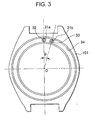
- Fig. 3 is a front view showing the wristwatch-type information processing device in Fig. 2 from which a rotary bezel is removed.
- holes 31a and 31b are formed at the drum 101, and a pulse-number detection sensor unit 32 and a rotational-direction detection sensor unit 33 are arranged respectively within the holes 31a and 31b.
- the pulse-number detection sensor unit 32 and the rotational-direction detection sensor unit 33 are so arranged that a line connecting the pulse-number detection sensor unit 32 with the center O of rotation of the rotary bezel 102 and a line connecting the rotational-direction detection sensor unit 33 with the center O cooperate to form an angle ⁇ 1 .
- the pulse-number detection sensor unit 32 is arranged below (verso side of Fig. 2) one of the symbols pointed by the pointer 110 ( in the case of Fig. 2). The angle ⁇ 1 will be described later in more detail.
- Fig. 4 is a view as viewed along a line IV-IV of Fig. 2.
- an optical pattern 41 is formed annularly so as to correspond to the annular series of the symbols indicated at the upper surface of the rotary bezel 102.
- a sensor cover glass 42 for protecting the pulse-number detection sensor unit 32 is mounted on the drum 101.
- the sensor cover glass is a transparent member that permits light passes between the pulse-number detection sensor unit 32 and the optical pattern 41.
- a packing 43 is arranged between the inner surface of the hole 31a of the drum 101 and the sensor cover glass 42.
- a closed space is formed below the sensor cover glass 42, and it is possible to prevent the lower part of the sensor cover glass 42 from being exposed water or the like.
- the pulse-number detection sensor unit 32 is arranged below the sensor cover glass 42.
- the pulse-number detection sensor unit 32 is provided with an LED (light emitting diode) 44, a photo-diode 45, a light shielding plate 44a arranged between the LED 44 and the photo-diode 45, and substrates 46.
- the LED 44 emits a light toward the optical pattern 41.
- the photo-diode 45 receives the reflected light from the optical pattern 41.
- the pulse-number detection sensor unit 32 generates a series of pulse signals on the basis of the reflected light received by the photo-diode 45.
- the number of pulses generated by the pulse-number detection sensor unit 32 is counted by a data-signal generating element 81 (refer to Fig.
- the rotational-direction detection sensor unit 33 has an arrangement similar to the pulse-number detection sensor unit 32 and reads the optical pattern 41 to generate a series of pulse signals.
- a contact spring 47 is provided below the lower substrate 46 of the pulse-number detection sensor unit 32.
- the pulse-number detection sensor unit 32 is electrically connected to a CPU of the wristwatch-type information processing device 100.
- a lead line may be provided in place of the contact spring 47.
- a circular groove 34 is formed in the upper surface of the drum 101.
- a projected ridge 48 which projects downwardly is formed on the lower surface of the rotary bezel 102.
- the projected ridge 48 is slidably fitted in the groove 34.
- An O-ring 49 is arranged between the inner surface of the rotary bezel 102 and the outer surface of the drum 101.
- Fig. 5 is a view showing the lower surface of the rotary bezel 102.
- the optical pattern 41 is provided with absorption areas 41a which absorb most of the light irradiated by the LED 44, and reflected areas 41b which reflect most of the light irradiated by the LED 44.
- the absorption areas 41a and the reflected areas 41b are formed alternately at regular angular intervals of an angle ⁇ 2 .
- the angle ⁇ 2 equals to 360/ n (degrees) where n is an even member that is the number of symbols on the upper surface of the rotary bezel 102.
- the pulse-number detection sensor unit 32 reads the absorption areas 41a and the reflected areas 41b alternately when the user rotates the rotary bezel 102, whereby it is possible to generate the series of pulse signals shown in Fig. 6. This pulse number is detected whereby it is possible to detect the rotational angle of the rotary bezel 102.
- the rotational-direction detection sensor unit 33 also generates a series of pulse signals similarly.
- ⁇ 1 ⁇ 2 + ⁇ 2 /4 .
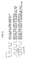
- the phase of signals of unit 33 leads that of unit 32 by 3 t /8. If the rotary bezel 102 is rotated in the counterclockwise direction, the phase of unit 33 lags behind that of unit 32 by 3 t /8. The phase lead or phase lag is detected whereby it is possible to detect the rotational direction of the rotary bezel 102.
- series of pulse signals shown in Fig. 8 are generated. As shown in Fig. 8, if the rotary bezel 102 is rotated in the clockwise direction, the phase of signals of unit 33 leads that of unit 32 by t /4. If the rotary bezel 102 is rotated in the counterclockwise direction, the phase of unit 33 lags behind that of unit 32 by t /4. Therefore, ⁇ 1 may be optional as long as a phase difference is generated in the series of pulse signals which are generated by the pulse-number detection sensor unit 32 and the rotational-direction detection sensor unit 33.
- the reference numeral 81 denotes a data-signal generating element (signal generating means).
- the data-signal generating element 81 has a pulse-number counter for counting the number of pulse signals generated by the pulse-number detection sensor unit 32 and the rotational-direction detection sensor unit 33, thereby detecting the rotational angle and the rotational direction of the rotary bezel 102.
- the data-signal generating element 81 refers to a data table 82 in which data corresponding to rotational angles and rotational directions of the rotary bezel 102 are stored, selects one of the data on the basis of the direction results, and outputs the selected datum as a data signal.
- a character generator 83 controls the display device 104 on the basis of the data signal, so that the display device 104 displays the symbol.
- the starting point switch 108 switches the wristwatch-type information processing device 100 to a data input state.
- the pulse-number counter of the data-signal generating element 81 is reset to zero so that the pulse-number detection sensor unit 32 and the rotational-direction detection sensor unit 33 are prepared to detect.
- the decision switch 105 may be pushed by the user for selecting the data signal which is generated by the data-signal generating element 81.
- the deletion switch 106 may be pushed by the user for deleting the data signal generated by the data-signal generating element 81.
- the voiced consonant mark switch 107 may be pushed to add the voiced consonant mark in Japanese.
- the voiced consonant mark switch 107 adds the index called the voiced consonant mark (dakuten) to the right upper side of the Japanese character for converting a Japanese character into If the data signal corresponds to English characters, the voiced consonant mark switch 107 is used to switch from capital letter mode to the small letter mode and in reverse.
- the data signals which are generated by the data-signal generating element 81 are not intended to be limited to correspond to symbols, and may correspond to commands for editing such as line feeding or for exchanging mode, (e.g., between a time display mode and a character input mode) of the information processing device 100.
- the data corresponding to commands are stored in the data table 82 and may be read out on the basis of the rotational angle and the rotational direction of the rotary bezel 102, so that the data-signal generating element 81 outputs data signals corresponding to commands.
- the user sets the rotary bezel 102 to a predetermined initial position.
- the initial position is where the rotary bezel 102 is in the state shown in Fig. 2: the Japanese character is pointed by the pointer 110.
- the user depresses the starting point switch 108, whereby the wristwatch-type information processing device 100 enters the data input state, and the pulse-number detection sensor unit 32 and the rotational-direction detect ion sensor unit 33 are prepared to detect the rotational angle and the rotational direction of the rotary bezel 102.
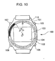
- the Japanese character the rotary bezel 102 is rotated in the counterclockwise direction, as shown in Fig. 10, to a position where the Japanese character is pointed by the pointer 110.
- the pulse-number detection sensor unit 32 and the rotational-direction detection sensor unit 33 generate the series of the pulse signals, whereby the data-signal generating element 81 detects the rotational angle ⁇ of the rotary bezel 102 and the rotational direction of the rotary bezel 102.
- a data signal corresponding to is generated by the data-signal generating element 81 on the basis of the detected rotational angle and the detected rotational direction, so that the Japanese,character is displayed on the display device 104.
- the decision switch 105 is depressed, the Japanese character is selected, and then, the device enters a standby state for waiting for next data. Furthermore, if the deletion switch 106 is depressed, the Japanese character is deleted, and then, the device enters the standby state. Further, if the voiced consonant mark switch 107 is depressed, the voiced consonant mark is added to the Japanese character and the Japanese character is displayed on the display device 104.
- the information processing device 100 can be readily made small because the arrangement is simple although a multiplicity of data corresponding to symbols and commands can be entered. Accordingly, it is possible to shape it into the wristwatch-type as described previously.
- the pulse-number detection sensor unit 32 and the rotational-direction detection sensor unit 33 are arranged within the holes 31a and 31b which are formed in the drum 101.
- the holes 31a and 31b are closed by the sensor cover glass 42 and the packing 43. Accordingly, this wristwatch-type information processing device 100 is excellent in water proofing.
- the projected ridge 48 formed on the rotary bezel 102 is fitted into the groove 34 which is formed in the drum 101, the light from outside is prevented from entering the neighborhood of the pulse-number detection sensor unit 32 and the rotational-direction detection sensor unit 33. Thus, malfunctions in the detection can be reduced.
- the wristwatch-type information processing device 100 since the data is able to be input by rotating the rotary bezel 102 and depressing the decision switch 105, the data input operation is simple. Furthermore, since the symbol pointed by the pointer 110 among many symbols on the rotary bezel 102 is input, misoperation such as misinput is reduced.
- the symbols may not be indicated on the upper surface of the rotary bezel 102.
- this modification can be realized since the data signal may be generated on the basis of the rotational angle and the rotational direction of the rotary bezel 102 from the position where the starting point switch 108 has been depressed. With this arrangement, it is unnecessary to set the rotary bezel 102 to the above-described initial position for inputting the data. Thus, the input operation is further simplified.
- the data are stored in the data table 82 regularly for facilitating user' s search.
- "A" is first displayed on the display device 104.
- "B” is displayed.
- "C” is displayed.
- the order of symbols (e.g., alphabet) with respect to the stored data is associated to the rotational angle of the rotary bezel 102. Therefore, it is easy to rotate for searching a necessary data.
- a wristwatch-type information processing device according to a second embodiment of the present invention will be described with reference to Figs. 11, 12 and 13.
- Figs. 11, 12 and 13 the same reference numerals are attached to components common to those of the first embodiment, and the description of the common components will be omitted.
- a mechanical switch (detection mechanism) 10 is provided in the drum 101 and is arranged at the position which confronts the optical pattern 41 (not shown in Fig. 11).
- Fig. 12 is a view showing an example of the mechanical switch 10.
- the mechanical switch 10 comprises a pin 111 which is slidably inserted into a hole 10a formed in the drum 101, and a circuit spring 112 which is in contact with the lower end of the pin 111 to push the pin 111 upwardly.
- a recess 113 is formed at the lower surface of the rotary bezel 102 at a position which correspond to one of the symbols on the upper surface of the rotary bezel 102.
- the recess 113 is formed at the position corresponding to Therefore, when the pointer 110 shown in Fig. 2 points the recess 113 comes to the position where the recess 113 confronts the mechanical switch 10.
- the circuit spring 112 as a switch is moved away from the circuit switch pattern 114 when the initial position (a reference position) is pointed by the pointer 110. Consequently, the pulse-number detection sensor unit 32 and the rotational-direction detection sensor unit 33 are reset, so that the detection of the rotational angle and the rotational direction from the position is started. Accordingly, it is unnecessary to adjust the rotary bezel 102 to the initial position (e.g., to adjust to the pointer 110), so that the input operation is simplified.
- the structure and the position of the mechanical switch 10 are not intended to be limited to those in the above-described embodiment, and may be optional. In an alteration, it is possible that a switch is turned on when the initial position (reference position) passes the pointer 110 at the rotation of the rotary bezel 102.
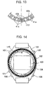
- Fig. 14 the same reference numerals are attached to components which are common to those of the first or second embodiment, and the description thereof will be omitted.
- symbols are arranged along two circles and indicated on the upper surface of the rotary bezel 102 by printing or any suitable manner.
- An inner-and-outer circle selection switch 121 is arranged on the periphery of the drum 101.
- the user can select any one of the symbols indicated at the inner circle and the outer circle by the inner-and-outer circle selection switch 121.
- the inner circle is selected at the state shown in Fig. 14, "A" is displayed on the display device 104.
- the Japanese character is displayed on the display device 104. Accordingly, it is possible to input a number of data twice as much as that of the first or second embodiment.
- a kanji conversion function which converts input characters to kanjis (Chinese characters) may be provided.
- the information processing device is not intended to be limited to the above-described wristwatch type. Rather, it is possible to apply the present invention to any other information processing devices including a portable telephone and a portable information processing terminal. In addition, it is possible to use a disk as a rotary body instead of the rotary bezel.
Landscapes
- Physics & Mathematics (AREA)
- General Physics & Mathematics (AREA)
- Electric Clocks (AREA)
- Input From Keyboards Or The Like (AREA)
- Vehicle Body Suspensions (AREA)
- Measuring Pulse, Heart Rate, Blood Pressure Or Blood Flow (AREA)
- Monitoring And Testing Of Nuclear Reactors (AREA)
- Debugging And Monitoring (AREA)
- Saccharide Compounds (AREA)
- Indicating Or Recording The Presence, Absence, Or Direction Of Movement (AREA)
- Position Input By Displaying (AREA)
- Photometry And Measurement Of Optical Pulse Characteristics (AREA)
Applications Claiming Priority (5)
| Application Number | Priority Date | Filing Date | Title |
|---|---|---|---|
| JP31862797 | 1997-11-19 | ||
| JP31862797 | 1997-11-19 | ||
| JP4554798 | 1998-02-26 | ||
| JP10045547A JPH11211862A (ja) | 1997-11-19 | 1998-02-26 | 情報処理装置 |
| PCT/JP1998/005145 WO1999026117A1 (en) | 1997-11-19 | 1998-11-16 | Information processor |
Publications (3)
| Publication Number | Publication Date |
|---|---|
| EP0974879A1 true EP0974879A1 (de) | 2000-01-26 |
| EP0974879A4 EP0974879A4 (de) | 2003-06-18 |
| EP0974879B1 EP0974879B1 (de) | 2007-07-25 |
Family
ID=26385557
Family Applications (1)
| Application Number | Title | Priority Date | Filing Date |
|---|---|---|---|
| EP98953060A Expired - Lifetime EP0974879B1 (de) | 1997-11-19 | 1998-11-16 | Datenverarbeitungsvorrichtung |
Country Status (6)
| Country | Link |
|---|---|
| US (1) | US6575618B1 (de) |
| EP (1) | EP0974879B1 (de) |
| JP (1) | JPH11211862A (de) |
| AT (1) | ATE368245T1 (de) |
| DE (1) | DE69838132T2 (de) |
| WO (1) | WO1999026117A1 (de) |
Cited By (4)
| Publication number | Priority date | Publication date | Assignee | Title |
|---|---|---|---|---|
| GB2379286A (en) * | 2001-08-29 | 2003-03-05 | Innomind Internat Ltd | Electronic multi-function watch |
| EP3032360A1 (de) * | 2014-12-12 | 2016-06-15 | The Swatch Group Research and Development Ltd. | Uhr mit manipulierbarer lunette |
| EP3336618A1 (de) * | 2016-12-16 | 2018-06-20 | ETA SA Manufacture Horlogère Suisse | Armbanduhrgehäuse mit steuerung mittels drehbarem ring |
| WO2021090200A1 (fr) * | 2019-11-04 | 2021-05-14 | Laurent Favre | Dispositif mécatronique agencé pour s'intégrer dans un appareil portatif comportant une pièce mécanique rotative servant à afficher et saisir un code pour exécuter une commande |
Families Citing this family (43)
| Publication number | Priority date | Publication date | Assignee | Title |
|---|---|---|---|---|
| ATE533091T1 (de) | 2000-12-01 | 2011-11-15 | Lvmh Swiss Mft Sa | Uhrengehäuse |
| US20030039175A1 (en) * | 2001-08-24 | 2003-02-27 | Gold Stacey Beth | Portable, hands-free mechanical timers for alerting tasks and method for using same |
| US20080290261A1 (en) * | 2004-06-30 | 2008-11-27 | Steve Doe | Optical Encoder |
| CN100397965C (zh) * | 2004-08-16 | 2008-06-25 | 明基电通股份有限公司 | 电子装置及其图像结构 |
| JP4605352B2 (ja) * | 2004-08-17 | 2011-01-05 | Nok株式会社 | 磁気ロータリエンコーダ用パルサーリング |
| USD564905S1 (en) * | 2007-04-04 | 2008-03-25 | Movado Llc | Watch |
| CN102063051B (zh) * | 2010-11-12 | 2013-07-03 | 鸿富锦精密工业(深圳)有限公司 | 腕带式装置 |
| US11175747B2 (en) * | 2013-02-04 | 2021-11-16 | Pixart Imaging Inc. | Optical processing apparatus and operating method thereof |
| US20140269218A1 (en) * | 2013-03-15 | 2014-09-18 | Jeffrey Herold | Watch Engaged ATIS Reminder Systems |
| US9753436B2 (en) | 2013-06-11 | 2017-09-05 | Apple Inc. | Rotary input mechanism for an electronic device |
| CN109634447B (zh) | 2013-08-09 | 2022-04-19 | 苹果公司 | 用于电子设备的触觉开关 |
| WO2015122885A1 (en) | 2014-02-12 | 2015-08-20 | Bodhi Technology Ventures Llc | Rejection of false turns of rotary inputs for electronic devices |
| US10190891B1 (en) | 2014-07-16 | 2019-01-29 | Apple Inc. | Optical encoder for detecting rotational and axial movement |
| US10599101B2 (en) | 2014-09-02 | 2020-03-24 | Apple Inc. | Wearable electronic device |
| KR101940943B1 (ko) | 2015-03-05 | 2019-01-21 | 애플 인크. | 방향 종속 광학 특성을 갖는 광학 인코더 |
| WO2016144919A1 (en) | 2015-03-08 | 2016-09-15 | Apple Inc. | Compressible seal for rotatable and translatable input mechanisms |
| US10018966B2 (en) | 2015-04-24 | 2018-07-10 | Apple Inc. | Cover member for an input mechanism of an electronic device |
| KR102353456B1 (ko) * | 2015-05-07 | 2022-01-21 | 삼성전자주식회사 | 회전 인식 장치 및 그를 구비하는 전자 장치 |
| US10386941B2 (en) | 2015-06-16 | 2019-08-20 | Intel Corporation | Gyratory sensing system to enhance wearable device user experience via HMI extension |
| TWM516175U (zh) * | 2015-07-23 | 2016-01-21 | 廣達電腦股份有限公司 | 智慧型手錶 |
| US9891651B2 (en) | 2016-02-27 | 2018-02-13 | Apple Inc. | Rotatable input mechanism having adjustable output |
| US10551798B1 (en) | 2016-05-17 | 2020-02-04 | Apple Inc. | Rotatable crown for an electronic device |
| US10061399B2 (en) | 2016-07-15 | 2018-08-28 | Apple Inc. | Capacitive gap sensor ring for an input device |
| US10019097B2 (en) | 2016-07-25 | 2018-07-10 | Apple Inc. | Force-detecting input structure |
| KR102355149B1 (ko) * | 2017-04-25 | 2022-01-25 | 삼성전자주식회사 | 분리형 입력 장치를 포함하는 전자 장치 |
| US10664074B2 (en) | 2017-06-19 | 2020-05-26 | Apple Inc. | Contact-sensitive crown for an electronic watch |
| US10962935B1 (en) | 2017-07-18 | 2021-03-30 | Apple Inc. | Tri-axis force sensor |
| TWI687843B (zh) * | 2018-05-07 | 2020-03-11 | 仁寶電腦工業股份有限公司 | 穿戴式裝置、及其通知系統與通知方法 |
| US11029764B2 (en) * | 2018-06-12 | 2021-06-08 | Pixart Imaging Inc. | Optical detection device and related turntable watch |
| US11360440B2 (en) | 2018-06-25 | 2022-06-14 | Apple Inc. | Crown for an electronic watch |
| US11561515B2 (en) | 2018-08-02 | 2023-01-24 | Apple Inc. | Crown for an electronic watch |
| US11181863B2 (en) | 2018-08-24 | 2021-11-23 | Apple Inc. | Conductive cap for watch crown |
| US12259690B2 (en) | 2018-08-24 | 2025-03-25 | Apple Inc. | Watch crown having a conductive surface |
| CN209560398U (zh) | 2018-08-24 | 2019-10-29 | 苹果公司 | 电子表 |
| US11194298B2 (en) | 2018-08-30 | 2021-12-07 | Apple Inc. | Crown assembly for an electronic watch |
| CN209625187U (zh) | 2018-08-30 | 2019-11-12 | 苹果公司 | 电子手表和电子设备 |
| US11164917B1 (en) * | 2018-09-14 | 2021-11-02 | Apple Inc. | Electronic devices with illuminated display borders |
| US11194299B1 (en) | 2019-02-12 | 2021-12-07 | Apple Inc. | Variable frictional feedback device for a digital crown of an electronic watch |
| KR102821845B1 (ko) * | 2019-11-22 | 2025-06-17 | 삼성전자주식회사 | 생체 신호 획득을 위한 생체 센서 및 전극을 포함하는 전자 장치 |
| US11550268B2 (en) | 2020-06-02 | 2023-01-10 | Apple Inc. | Switch module for electronic crown assembly |
| US12092996B2 (en) | 2021-07-16 | 2024-09-17 | Apple Inc. | Laser-based rotation sensor for a crown of an electronic watch |
| US12189347B2 (en) | 2022-06-14 | 2025-01-07 | Apple Inc. | Rotation sensor for a crown of an electronic watch |
| US12596334B2 (en) | 2023-02-07 | 2026-04-07 | Apple Inc. | Crown for an electronic watch |
Family Cites Families (33)
| Publication number | Priority date | Publication date | Assignee | Title |
|---|---|---|---|---|
| GB1391637A (en) * | 1971-12-27 | 1975-04-23 | Suwa Seikosha Kk | Electronic timepieces and electronic calculators |
| JPS5073339A (de) | 1973-11-02 | 1975-06-17 | ||
| JPS5349308Y2 (de) * | 1973-11-07 | 1978-11-27 | ||
| CH608323B (fr) * | 1975-11-19 | Ebauches Sa | Piece d'horlogerie electronique universelle. | |
| NL178738C (nl) * | 1979-08-16 | 1986-11-17 | Philips Nv | Instelschakeling. |
| CH646301GA3 (de) * | 1981-12-23 | 1984-11-30 | ||
| JPS607316A (ja) | 1983-06-28 | 1985-01-16 | Asahi Optical Co Ltd | 角度測定装置 |
| JPS6166927A (ja) | 1984-09-10 | 1986-04-05 | Canon Inc | ロ−タリ−エンコ−ダ− |
| DE3510861C2 (de) * | 1984-11-09 | 1986-09-25 | Gebrüder Junghans GmbH, 7230 Schramberg | Anzeigestellungs-Detektionseinrichtung für eine Uhr, insbesondere eine Funkuhr |
| JPH0648299B2 (ja) * | 1985-02-14 | 1994-06-22 | セイコー電子工業株式会社 | 電子時計用回転スイッチ |
| JPS6265594A (ja) | 1985-09-17 | 1987-03-24 | Matsushita Electric Ind Co Ltd | スピ−カ |
| JPS6265594U (de) * | 1985-10-15 | 1987-04-23 | ||
| CH662700GA3 (de) * | 1985-10-16 | 1987-10-30 | ||
| JPS63151807A (ja) | 1986-12-16 | 1988-06-24 | Fujitsu Ten Ltd | 角度検出装置 |
| US4947166A (en) * | 1988-02-22 | 1990-08-07 | Dynamics Research Corporation | Single track absolute encoder |
| US4914831A (en) * | 1988-03-04 | 1990-04-10 | Casio Computer Co., Ltd. | Rotation detecting apparatus |
| JPH022689A (ja) | 1988-06-16 | 1990-01-08 | Fujitsu Ltd | フォト・ダイオードの製造方法 |
| JPH022689U (de) * | 1988-06-17 | 1990-01-09 | ||
| JPH02268227A (ja) * | 1989-03-24 | 1990-11-01 | Micron Instr Corp | エンコーダ |
| JPH0314419U (de) * | 1989-06-26 | 1991-02-14 | ||
| JP2904900B2 (ja) | 1990-09-29 | 1999-06-14 | 大日本印刷株式会社 | Icカード用組立テーブル |
| US5103225A (en) * | 1990-12-24 | 1992-04-07 | Pitney Bowes Inc. | Motor-driven positioning system with reflective optical encoder |
| JPH04138295U (ja) * | 1991-06-17 | 1992-12-24 | セイコー電子工業株式会社 | 回転ベゼルロータリースイツチ機構 |
| CH683484B5 (fr) * | 1992-08-03 | 1994-09-30 | Ebauchesfabrik Eta Ag | Pièce d'horlogerie apte à recevoir des messages radiodiffusés munie d'un dispositif de commande à bille. |
| CH685273B5 (de) * | 1992-10-05 | 1995-11-30 | Andreas Tschannen | Uhr, insbesondere Armbanduhr. |
| FR2724081A1 (fr) * | 1994-08-23 | 1996-03-01 | Ebauchesfabrik Eta Ag | Telephone dont le numero d'appel est compose par une couronne du type horloger |
| CH690513A5 (de) * | 1995-04-19 | 2000-09-29 | Asulab Sa | Universaluhr mit drehbarem Aussenring. |
| CH689531B5 (fr) * | 1995-07-17 | 1999-11-15 | GERBER MARCELm | Montre électronique à lunette tournante, notamment montre-bracelet. |
| DE69719148T2 (de) * | 1996-05-24 | 2003-07-24 | Seiko Epson Corp., Tokio/Tokyo | Positionsgeber, kodierungsplatte, verfahren zur positionserfassung, zeitgeber und elektronisches gerät |
| DE19733049A1 (de) * | 1997-07-31 | 1999-02-04 | Bosch Gmbh Robert | Optischer Inkrementgeber |
| JP3329271B2 (ja) * | 1998-05-26 | 2002-09-30 | トヨタ自動車株式会社 | 操舵角検出装置及びその異常検出装置 |
| JP3627531B2 (ja) * | 1998-09-30 | 2005-03-09 | セイコーエプソン株式会社 | 情報処理装置 |
| JP2001066383A (ja) * | 1999-08-30 | 2001-03-16 | Seiko Epson Corp | 情報処理装置 |
-
1998
- 1998-02-26 JP JP10045547A patent/JPH11211862A/ja not_active Withdrawn
- 1998-11-16 AT AT98953060T patent/ATE368245T1/de not_active IP Right Cessation
- 1998-11-16 EP EP98953060A patent/EP0974879B1/de not_active Expired - Lifetime
- 1998-11-16 US US09/341,902 patent/US6575618B1/en not_active Expired - Fee Related
- 1998-11-16 DE DE69838132T patent/DE69838132T2/de not_active Expired - Lifetime
- 1998-11-16 WO PCT/JP1998/005145 patent/WO1999026117A1/ja not_active Ceased
Cited By (8)
| Publication number | Priority date | Publication date | Assignee | Title |
|---|---|---|---|---|
| GB2379286A (en) * | 2001-08-29 | 2003-03-05 | Innomind Internat Ltd | Electronic multi-function watch |
| EP3032360A1 (de) * | 2014-12-12 | 2016-06-15 | The Swatch Group Research and Development Ltd. | Uhr mit manipulierbarer lunette |
| WO2016092027A1 (fr) * | 2014-12-12 | 2016-06-16 | The Swatch Group Research And Development Ltd | Objet portable avec lunette manipulable |
| EP3336618A1 (de) * | 2016-12-16 | 2018-06-20 | ETA SA Manufacture Horlogère Suisse | Armbanduhrgehäuse mit steuerung mittels drehbarem ring |
| WO2018108472A1 (fr) | 2016-12-16 | 2018-06-21 | Eta Sa Manufacture Horlogère Suisse | Boite de montre avec molette de commande |
| CN109313413A (zh) * | 2016-12-16 | 2019-02-05 | Eta瑞士钟表制造股份有限公司 | 具有控制指轮的手表表壳 |
| CN109313413B (zh) * | 2016-12-16 | 2021-03-23 | Eta瑞士钟表制造股份有限公司 | 具有控制指轮的手表表壳 |
| WO2021090200A1 (fr) * | 2019-11-04 | 2021-05-14 | Laurent Favre | Dispositif mécatronique agencé pour s'intégrer dans un appareil portatif comportant une pièce mécanique rotative servant à afficher et saisir un code pour exécuter une commande |
Also Published As
| Publication number | Publication date |
|---|---|
| DE69838132T2 (de) | 2008-04-10 |
| JPH11211862A (ja) | 1999-08-06 |
| ATE368245T1 (de) | 2007-08-15 |
| EP0974879A4 (de) | 2003-06-18 |
| US6575618B1 (en) | 2003-06-10 |
| WO1999026117A1 (en) | 1999-05-27 |
| EP0974879B1 (de) | 2007-07-25 |
| DE69838132D1 (de) | 2007-09-06 |
Similar Documents
| Publication | Publication Date | Title |
|---|---|---|
| EP0974879B1 (de) | Datenverarbeitungsvorrichtung | |
| US6407379B1 (en) | Information processor | |
| EP1431713B1 (de) | Bewegungskodierer | |
| EP2045694B1 (de) | Tragbare elektronische Vorrichtung mit mausähnlichen Fähigkeiten | |
| US6798401B2 (en) | Optical system for inputting pointer and character data into electronic equipment | |
| GB2375585A (en) | Combined optical fingertip tracker and push-button for controlling a pointer on a display screen | |
| WO2008011361A2 (en) | User interfacing | |
| CA2609155A1 (en) | Free-space pointing and handwriting | |
| AU2005203634A1 (en) | Integrated keypad system | |
| AU5234498A (en) | Display pointing device | |
| US20200133474A1 (en) | Accommodative user interface for handheld electronic devices | |
| JP2000241199A (ja) | 情報処理装置および情報処理装置の情報入力方法 | |
| CN112947038B (zh) | 设有控制部件的表 | |
| JP2001060137A (ja) | 情報処理装置および情報入力方法 | |
| JPH11271099A (ja) | 情報処理装置 | |
| JP3654071B2 (ja) | 携帯機器 | |
| JP2001066383A (ja) | 情報処理装置 | |
| JP2001067173A (ja) | 情報処理装置および情報入力方法 | |
| JP2000207096A (ja) | 情報処理装置 | |
| JPH11258000A (ja) | 情報処理装置 | |
| JP2000242410A (ja) | 情報処理装置 | |
| JPH11281400A (ja) | 回転検出装置及び回転検出方法 | |
| HK40055719A (en) | Watch provided with a control member | |
| HK40055719B (en) | Watch provided with a control member | |
| JPH11258362A (ja) | 情報処理装置 |
Legal Events
| Date | Code | Title | Description |
|---|---|---|---|
| PUAI | Public reference made under article 153(3) epc to a published international application that has entered the european phase |
Free format text: ORIGINAL CODE: 0009012 |
|
| 17P | Request for examination filed |
Effective date: 19991126 |
|
| AK | Designated contracting states |
Kind code of ref document: A1 Designated state(s): AT BE CH CY DE DK ES FI FR GB GR IE IT LI LU MC NL PT SE |
|
| A4 | Supplementary search report drawn up and despatched |
Effective date: 20030506 |
|
| RIC1 | Information provided on ipc code assigned before grant |
Ipc: 7G 04C 3/00 B Ipc: 7G 01D 5/30 B Ipc: 7G 04B 19/28 B Ipc: 7G 04G 1/00 A |
|
| 17Q | First examination report despatched |
Effective date: 20040917 |
|
| GRAP | Despatch of communication of intention to grant a patent |
Free format text: ORIGINAL CODE: EPIDOSNIGR1 |
|
| GRAS | Grant fee paid |
Free format text: ORIGINAL CODE: EPIDOSNIGR3 |
|
| GRAA | (expected) grant |
Free format text: ORIGINAL CODE: 0009210 |
|
| AK | Designated contracting states |
Kind code of ref document: B1 Designated state(s): AT BE CH CY DE DK ES FI FR GB GR IE IT LI LU MC NL PT SE |
|
| REG | Reference to a national code |
Ref country code: GB Ref legal event code: FG4D |
|
| REG | Reference to a national code |
Ref country code: CH Ref legal event code: EP |
|
| REG | Reference to a national code |
Ref country code: IE Ref legal event code: FG4D |
|
| REF | Corresponds to: |
Ref document number: 69838132 Country of ref document: DE Date of ref document: 20070906 Kind code of ref document: P |
|
| REG | Reference to a national code |
Ref country code: CH Ref legal event code: NV Representative=s name: PATENTANWAELTE SCHAAD, BALASS, MENZL & PARTNER AG |
|
| ET | Fr: translation filed | ||
| PG25 | Lapsed in a contracting state [announced via postgrant information from national office to epo] |
Ref country code: PT Free format text: LAPSE BECAUSE OF FAILURE TO SUBMIT A TRANSLATION OF THE DESCRIPTION OR TO PAY THE FEE WITHIN THE PRESCRIBED TIME-LIMIT Effective date: 20071226 Ref country code: NL Free format text: LAPSE BECAUSE OF FAILURE TO SUBMIT A TRANSLATION OF THE DESCRIPTION OR TO PAY THE FEE WITHIN THE PRESCRIBED TIME-LIMIT Effective date: 20070725 Ref country code: FI Free format text: LAPSE BECAUSE OF FAILURE TO SUBMIT A TRANSLATION OF THE DESCRIPTION OR TO PAY THE FEE WITHIN THE PRESCRIBED TIME-LIMIT Effective date: 20070725 Ref country code: ES Free format text: LAPSE BECAUSE OF FAILURE TO SUBMIT A TRANSLATION OF THE DESCRIPTION OR TO PAY THE FEE WITHIN THE PRESCRIBED TIME-LIMIT Effective date: 20071105 |
|
| NLV1 | Nl: lapsed or annulled due to failure to fulfill the requirements of art. 29p and 29m of the patents act | ||
| PG25 | Lapsed in a contracting state [announced via postgrant information from national office to epo] |
Ref country code: AT Free format text: LAPSE BECAUSE OF FAILURE TO SUBMIT A TRANSLATION OF THE DESCRIPTION OR TO PAY THE FEE WITHIN THE PRESCRIBED TIME-LIMIT Effective date: 20070725 |
|
| PG25 | Lapsed in a contracting state [announced via postgrant information from national office to epo] |
Ref country code: BE Free format text: LAPSE BECAUSE OF FAILURE TO SUBMIT A TRANSLATION OF THE DESCRIPTION OR TO PAY THE FEE WITHIN THE PRESCRIBED TIME-LIMIT Effective date: 20070725 |
|
| PG25 | Lapsed in a contracting state [announced via postgrant information from national office to epo] |
Ref country code: GR Free format text: LAPSE BECAUSE OF FAILURE TO SUBMIT A TRANSLATION OF THE DESCRIPTION OR TO PAY THE FEE WITHIN THE PRESCRIBED TIME-LIMIT Effective date: 20071026 Ref country code: DK Free format text: LAPSE BECAUSE OF FAILURE TO SUBMIT A TRANSLATION OF THE DESCRIPTION OR TO PAY THE FEE WITHIN THE PRESCRIBED TIME-LIMIT Effective date: 20070725 |
|
| PLBE | No opposition filed within time limit |
Free format text: ORIGINAL CODE: 0009261 |
|
| STAA | Information on the status of an ep patent application or granted ep patent |
Free format text: STATUS: NO OPPOSITION FILED WITHIN TIME LIMIT |
|
| PG25 | Lapsed in a contracting state [announced via postgrant information from national office to epo] |
Ref country code: SE Free format text: LAPSE BECAUSE OF FAILURE TO SUBMIT A TRANSLATION OF THE DESCRIPTION OR TO PAY THE FEE WITHIN THE PRESCRIBED TIME-LIMIT Effective date: 20071025 Ref country code: MC Free format text: LAPSE BECAUSE OF NON-PAYMENT OF DUE FEES Effective date: 20071130 |
|
| 26N | No opposition filed |
Effective date: 20080428 |
|
| PG25 | Lapsed in a contracting state [announced via postgrant information from national office to epo] |
Ref country code: IE Free format text: LAPSE BECAUSE OF NON-PAYMENT OF DUE FEES Effective date: 20071116 |
|
| PG25 | Lapsed in a contracting state [announced via postgrant information from national office to epo] |
Ref country code: CY Free format text: LAPSE BECAUSE OF FAILURE TO SUBMIT A TRANSLATION OF THE DESCRIPTION OR TO PAY THE FEE WITHIN THE PRESCRIBED TIME-LIMIT Effective date: 20070725 |
|
| PG25 | Lapsed in a contracting state [announced via postgrant information from national office to epo] |
Ref country code: LU Free format text: LAPSE BECAUSE OF NON-PAYMENT OF DUE FEES Effective date: 20071116 |
|
| PG25 | Lapsed in a contracting state [announced via postgrant information from national office to epo] |
Ref country code: IT Free format text: LAPSE BECAUSE OF NON-PAYMENT OF DUE FEES Effective date: 20071130 |
|
| PGFP | Annual fee paid to national office [announced via postgrant information from national office to epo] |
Ref country code: DE Payment date: 20101110 Year of fee payment: 13 |
|
| PGFP | Annual fee paid to national office [announced via postgrant information from national office to epo] |
Ref country code: GB Payment date: 20101110 Year of fee payment: 13 |
|
| REG | Reference to a national code |
Ref country code: DE Ref legal event code: R079 Ref document number: 69838132 Country of ref document: DE Free format text: PREVIOUS MAIN CLASS: G04G0001000000 Ipc: G04G0021000000 |
|
| REG | Reference to a national code |
Ref country code: DE Ref legal event code: R079 Ref document number: 69838132 Country of ref document: DE Free format text: PREVIOUS MAIN CLASS: G04G0001000000 Ipc: G04G0021000000 Effective date: 20110802 |
|
| PGFP | Annual fee paid to national office [announced via postgrant information from national office to epo] |
Ref country code: CH Payment date: 20111114 Year of fee payment: 14 Ref country code: FR Payment date: 20111118 Year of fee payment: 14 |
|
| REG | Reference to a national code |
Ref country code: CH Ref legal event code: PL |
|
| GBPC | Gb: european patent ceased through non-payment of renewal fee |
Effective date: 20121116 |
|
| PG25 | Lapsed in a contracting state [announced via postgrant information from national office to epo] |
Ref country code: CH Free format text: LAPSE BECAUSE OF NON-PAYMENT OF DUE FEES Effective date: 20121130 Ref country code: LI Free format text: LAPSE BECAUSE OF NON-PAYMENT OF DUE FEES Effective date: 20121130 |
|
| REG | Reference to a national code |
Ref country code: FR Ref legal event code: ST Effective date: 20130731 |
|
| REG | Reference to a national code |
Ref country code: DE Ref legal event code: R119 Ref document number: 69838132 Country of ref document: DE Effective date: 20130601 |
|
| PG25 | Lapsed in a contracting state [announced via postgrant information from national office to epo] |
Ref country code: DE Free format text: LAPSE BECAUSE OF NON-PAYMENT OF DUE FEES Effective date: 20130601 |
|
| PG25 | Lapsed in a contracting state [announced via postgrant information from national office to epo] |
Ref country code: GB Free format text: LAPSE BECAUSE OF NON-PAYMENT OF DUE FEES Effective date: 20121116 Ref country code: FR Free format text: LAPSE BECAUSE OF NON-PAYMENT OF DUE FEES Effective date: 20121130 |