EP0976601A2 - Réservoir de carburant avec dispositif de mesure de niveau - Google Patents
Réservoir de carburant avec dispositif de mesure de niveau Download PDFInfo
- Publication number
- EP0976601A2 EP0976601A2 EP99114128A EP99114128A EP0976601A2 EP 0976601 A2 EP0976601 A2 EP 0976601A2 EP 99114128 A EP99114128 A EP 99114128A EP 99114128 A EP99114128 A EP 99114128A EP 0976601 A2 EP0976601 A2 EP 0976601A2
- Authority
- EP
- European Patent Office
- Prior art keywords
- tank
- measuring device
- opening
- reservoir
- fuel tank
- Prior art date
- Legal status (The legal status is an assumption and is not a legal conclusion. Google has not performed a legal analysis and makes no representation as to the accuracy of the status listed.)
- Granted
Links
- 239000002828 fuel tank Substances 0.000 title claims abstract description 17
- 238000005259 measurement Methods 0.000 title 1
- 239000000446 fuel Substances 0.000 abstract description 15
- 239000004033 plastic Substances 0.000 description 3
- 238000010101 extrusion blow moulding Methods 0.000 description 2
- 239000000463 material Substances 0.000 description 2
- 238000007789 sealing Methods 0.000 description 2
- 238000004904 shortening Methods 0.000 description 2
- 229910000639 Spring steel Inorganic materials 0.000 description 1
- 238000005520 cutting process Methods 0.000 description 1
- 238000003780 insertion Methods 0.000 description 1
- 230000037431 insertion Effects 0.000 description 1
- 239000007788 liquid Substances 0.000 description 1
- 238000004519 manufacturing process Methods 0.000 description 1
- 238000000926 separation method Methods 0.000 description 1
- 239000007787 solid Substances 0.000 description 1
- 229920001169 thermoplastic Polymers 0.000 description 1
- 239000004416 thermosoftening plastic Substances 0.000 description 1
Images

Classifications
-
- B—PERFORMING OPERATIONS; TRANSPORTING
- B60—VEHICLES IN GENERAL
- B60K—ARRANGEMENT OR MOUNTING OF PROPULSION UNITS OR OF TRANSMISSIONS IN VEHICLES; ARRANGEMENT OR MOUNTING OF PLURAL DIVERSE PRIME-MOVERS IN VEHICLES; AUXILIARY DRIVES FOR VEHICLES; INSTRUMENTATION OR DASHBOARDS FOR VEHICLES; ARRANGEMENTS IN CONNECTION WITH COOLING, AIR INTAKE, GAS EXHAUST OR FUEL SUPPLY OF PROPULSION UNITS IN VEHICLES
- B60K15/00—Arrangement in connection with fuel supply of combustion engines or other fuel consuming energy converters, e.g. fuel cells; Mounting or construction of fuel tanks
- B60K15/03—Fuel tanks
- B60K15/06—Fuel tanks characterised by fuel reserve systems
- B60K15/061—Fuel tanks characterised by fuel reserve systems with level control
-
- B—PERFORMING OPERATIONS; TRANSPORTING
- B60—VEHICLES IN GENERAL
- B60K—ARRANGEMENT OR MOUNTING OF PROPULSION UNITS OR OF TRANSMISSIONS IN VEHICLES; ARRANGEMENT OR MOUNTING OF PLURAL DIVERSE PRIME-MOVERS IN VEHICLES; AUXILIARY DRIVES FOR VEHICLES; INSTRUMENTATION OR DASHBOARDS FOR VEHICLES; ARRANGEMENTS IN CONNECTION WITH COOLING, AIR INTAKE, GAS EXHAUST OR FUEL SUPPLY OF PROPULSION UNITS IN VEHICLES
- B60K15/00—Arrangement in connection with fuel supply of combustion engines or other fuel consuming energy converters, e.g. fuel cells; Mounting or construction of fuel tanks
- B60K15/03—Fuel tanks
- B60K15/077—Fuel tanks with means modifying or controlling distribution or motion of fuel, e.g. to prevent noise, surge, splash or fuel starvation
-
- F—MECHANICAL ENGINEERING; LIGHTING; HEATING; WEAPONS; BLASTING
- F02—COMBUSTION ENGINES; HOT-GAS OR COMBUSTION-PRODUCT ENGINE PLANTS
- F02M—SUPPLYING COMBUSTION ENGINES IN GENERAL WITH COMBUSTIBLE MIXTURES OR CONSTITUENTS THEREOF
- F02M37/00—Apparatus or systems for feeding liquid fuel from storage containers to carburettors or fuel-injection apparatus; Arrangements for purifying liquid fuel specially adapted for, or arranged on, internal-combustion engines
- F02M37/04—Feeding by means of driven pumps
- F02M37/08—Feeding by means of driven pumps electrically driven
- F02M37/10—Feeding by means of driven pumps electrically driven submerged in fuel, e.g. in reservoir
- F02M37/103—Mounting pumps on fuel tanks
-
- B—PERFORMING OPERATIONS; TRANSPORTING
- B60—VEHICLES IN GENERAL
- B60K—ARRANGEMENT OR MOUNTING OF PROPULSION UNITS OR OF TRANSMISSIONS IN VEHICLES; ARRANGEMENT OR MOUNTING OF PLURAL DIVERSE PRIME-MOVERS IN VEHICLES; AUXILIARY DRIVES FOR VEHICLES; INSTRUMENTATION OR DASHBOARDS FOR VEHICLES; ARRANGEMENTS IN CONNECTION WITH COOLING, AIR INTAKE, GAS EXHAUST OR FUEL SUPPLY OF PROPULSION UNITS IN VEHICLES
- B60K15/00—Arrangement in connection with fuel supply of combustion engines or other fuel consuming energy converters, e.g. fuel cells; Mounting or construction of fuel tanks
- B60K15/03—Fuel tanks
- B60K2015/0321—Fuel tanks characterised by special sensors, the mounting thereof
- B60K2015/03217—Fuel level sensors
-
- B—PERFORMING OPERATIONS; TRANSPORTING
- B60—VEHICLES IN GENERAL
- B60K—ARRANGEMENT OR MOUNTING OF PROPULSION UNITS OR OF TRANSMISSIONS IN VEHICLES; ARRANGEMENT OR MOUNTING OF PLURAL DIVERSE PRIME-MOVERS IN VEHICLES; AUXILIARY DRIVES FOR VEHICLES; INSTRUMENTATION OR DASHBOARDS FOR VEHICLES; ARRANGEMENTS IN CONNECTION WITH COOLING, AIR INTAKE, GAS EXHAUST OR FUEL SUPPLY OF PROPULSION UNITS IN VEHICLES
- B60K15/00—Arrangement in connection with fuel supply of combustion engines or other fuel consuming energy converters, e.g. fuel cells; Mounting or construction of fuel tanks
- B60K15/03—Fuel tanks
- B60K2015/03328—Arrangements or special measures related to fuel tanks or fuel handling
- B60K2015/03453—Arrangements or special measures related to fuel tanks or fuel handling for fixing or mounting parts of the fuel tank together
-
- F—MECHANICAL ENGINEERING; LIGHTING; HEATING; WEAPONS; BLASTING
- F02—COMBUSTION ENGINES; HOT-GAS OR COMBUSTION-PRODUCT ENGINE PLANTS
- F02D—CONTROLLING COMBUSTION ENGINES
- F02D33/00—Controlling delivery of fuel or combustion-air, not otherwise provided for
- F02D33/003—Controlling the feeding of liquid fuel from storage containers to carburettors or fuel-injection apparatus ; Failure or leakage prevention; Diagnosis or detection of failure; Arrangement of sensors in the fuel system; Electric wiring; Electrostatic discharge
-
- F—MECHANICAL ENGINEERING; LIGHTING; HEATING; WEAPONS; BLASTING
- F02—COMBUSTION ENGINES; HOT-GAS OR COMBUSTION-PRODUCT ENGINE PLANTS
- F02M—SUPPLYING COMBUSTION ENGINES IN GENERAL WITH COMBUSTIBLE MIXTURES OR CONSTITUENTS THEREOF
- F02M37/00—Apparatus or systems for feeding liquid fuel from storage containers to carburettors or fuel-injection apparatus; Arrangements for purifying liquid fuel specially adapted for, or arranged on, internal-combustion engines
- F02M37/0076—Details of the fuel feeding system related to the fuel tank
- F02M37/0082—Devices inside the fuel tank other than fuel pumps or filters
-
- Y—GENERAL TAGGING OF NEW TECHNOLOGICAL DEVELOPMENTS; GENERAL TAGGING OF CROSS-SECTIONAL TECHNOLOGIES SPANNING OVER SEVERAL SECTIONS OF THE IPC; TECHNICAL SUBJECTS COVERED BY FORMER USPC CROSS-REFERENCE ART COLLECTIONS [XRACs] AND DIGESTS
- Y10—TECHNICAL SUBJECTS COVERED BY FORMER USPC
- Y10T—TECHNICAL SUBJECTS COVERED BY FORMER US CLASSIFICATION
- Y10T137/00—Fluid handling
- Y10T137/8158—With indicator, register, recorder, alarm or inspection means
- Y10T137/8342—Liquid level responsive indicator, recorder or alarm
-
- Y—GENERAL TAGGING OF NEW TECHNOLOGICAL DEVELOPMENTS; GENERAL TAGGING OF CROSS-SECTIONAL TECHNOLOGIES SPANNING OVER SEVERAL SECTIONS OF THE IPC; TECHNICAL SUBJECTS COVERED BY FORMER USPC CROSS-REFERENCE ART COLLECTIONS [XRACs] AND DIGESTS
- Y10—TECHNICAL SUBJECTS COVERED BY FORMER USPC
- Y10T—TECHNICAL SUBJECTS COVERED BY FORMER US CLASSIFICATION
- Y10T137/00—Fluid handling
- Y10T137/8593—Systems
- Y10T137/85978—With pump
- Y10T137/86091—Resiliently mounted pump
Definitions
- the invention relates to a fuel tank for a motor vehicle according to the preamble of claim 1.
- the delivery unit located inside the fuel tank is provided with an electric fuel pump, through which the Engine of the motor vehicle is supplied with fuel.
- an electric fuel pump through which the Engine of the motor vehicle is supplied with fuel.
- tanks are made of thermoplastic used, preferably in one piece in extrusion blow molding getting produced.
- the conveyor unit with the Reservoir after manufacturing the tank by a mostly retrofit opening in the tank wall into the tank used.
- the Reservoir of the conveyor unit inserted into the tank through this opening has a correspondingly small volume, which for example in the order of 0.5 to 1 liter. This volume is in many cases considering the duration of the the aforementioned unfavorable operating conditions occurring in practice, during which little or no fuel from the volume surrounding the reservoir flows into the reservoir low.
- the reservoir may experience a reduction by a level measuring device attached to the outside of the conveyor unit for the main tank space surrounding the reservoir, which together with the conveyor through the opening in the Tank must be imported. Because the cross section of the opening the Contour of the delivery unit is determined and the measuring device is not may project significantly beyond this contour the need for the measuring device within the contour, d. i.e. to accommodate the cross section of the conveyor unit. This has the inevitable consequence that the volume of the reservoir is one experienced a corresponding reduction. Thus the volume of the Reservoirs are still below the size indicated by the cross section of the Opening in the tank wall is specified anyway.
- the invention has for its object a fuel tank of the type described in the introduction so that the The presence of a level measuring device is not inevitable leads to a reduction in the volume of the reservoir. Further should it be possible to arrange the level measuring device in such a way that it also allows the use of a reservoir whose cross section perpendicular to the longitudinal axis of the opening in the Tank wall inside the tank can be enlarged without Reservoir and level measuring device would be in the way of each other.
- the measuring device is separate from the conveyor unit is, it allows both parts, i.e. conveyor unit and Measuring device including the holder of the latter in the tank one after the other and therefore independently of each other and successively into their respective operating positions bring. Design and positioning are subject to also that of the measuring device depending on the change the level of any movements to be carried out less restrictions than when attaching the measuring device is the case at the conveyor unit.
- the holder for the measuring device as Ring is formed which in the edge of the closable opening the tank wall is attached.
- the measuring device transverse to the longitudinal axis of the opening in one Distance from the circumference of the opening. It is just for that required that the mounting ring for the measuring device with at least one z. B. substantially perpendicular to Longitudinal axis of the opening arm or the like. is provided, which at a distance from the mounting ring Measuring device carries. This gives the possibility of the measuring device so far from the opening and thus from that through the Position the opening of the conveyor unit inserted into the tank, that the reservoir within the tank to achieve a larger one Volume can be expanded without the measuring device would be in the way.
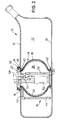
- the fuel tank 10 to be installed in a motor vehicle, the in one piece in the extrusion blow molding process from plastic, but also can be made in other ways is in its upper Wall 12 provided with an opening 14 through Cutting out a corresponding part of the wall, but can also be molded.
- the one in the Drawing shown embodiment is on the tank short nozzle 16 attached, which also the stiffening serves the tank wall. Through this opening, which in general, though not necessarily a circular one Has a cross section, a prepared conveyor unit 18 in the tank 10 used which is a reservoir 28 for the fuel has and essentially has the function of a trouble-free Fueling the motor of the motor vehicle ensure.
- the conveyor unit 18 has a bottom part 20 and a head part 22 provided that each limit the reservoir 28 at the end. Both parts 20 and 22 are supported by a support structure 24 connected and held together, which of four or more Last 26 of solid, elastically deformable material, that is for example spring steel or plastic. These ledges 26 are on the circumference of the conveyor unit 18 or in cross section approximately circular reservoirs 28 each 90 ° against each other staggered.
- the support structure 24 is on the outside from a tubular section 30 of preferably deformable Surround material such as rubber or plastic. This section 30 forms between the bottom part 20 and the head part 22 the deformable boundary wall of the reservoir 28, from which the fuel is taken that is fed to the engine becomes.
- the section 30 is both with the bottom part 20 as well as tightly connected to the head part 22, so that the reservoir in its operating position inside the tank (Fig. 2), apart from the necessary feed and discharge lines for the Fuel opposite the main space 32 surrounding the reservoir in tank 10 is complete.
- the attachment of the delivery unit 18 with the reservoir 28 in the tank 10 takes place in such a way that the conveyor unit 18 z. B. starting from the position shown in Fig. 1 as a unit by the Opening 14 in the upper wall of the tank 10 in the latter is introduced, the cross section of the conveyor unit 18 initially corresponds to the inner cross section of a retaining ring 34, which is placed on the nozzle 16 and for holding a Level measuring device 36 is used, in which the reservoir 28th surrounding space 32 is arranged and for measuring the level of fuel in this room.
- the retaining ring 34 thus has a cross section two legs that are approximately rectangular to each other.
- the extension or leg 40 in one on the socket 16 inside attached circumferential recess with a appropriate cross section is provided.
- Measuring device 36 On the retaining ring 34 is approximately radial to the longitudinal axis of the opening 14 extending arm 42 attached to the at its free end Measuring device 36 carries the usual way, for. B. as a lever, can be trained. So it is possible to use the measuring device 36 pivotally attached to the bracket arm 42 when the Measuring device with a not shown in the drawing Is provided float that floats on the fuel, wherein the angular position of the lever 44 carrying the float the level indicates. But it can also all other possible level measuring devices be used.
- the parts arranged within the reservoir 28, that is in particular electric fuel pump 52, pressure regulator 54 and Level measuring device 56 are not directly related with the invention so that it is not explained in detail need to be.
- the conveyor unit 18 designed so that the fuel from the surrounding Space 32 can flow into the reservoir 28.
- the supply of the Engine of the motor vehicle with fuel takes place via the line 58, which also like the other - electrical - lines is passed liquid-tight through the head part 22.
- the invention also provides the possibility of the bracket, especially the bracket arm 42, to execute or dimension such that the Level measuring device 36 is not only outside the contour the conveyor 18, but also independently of this in a distance from the conveyor, so that, as in Case of the embodiment shown in the drawing, the conveying unit 18 has an expansion after being introduced into the tank can experience without it being necessary to The presence of the measuring device 36 should be taken into account.
- the Application of the teaching according to the invention thus allows regarding the arrangement and design of the conveyor unit and measuring device a greater degree of freedom, being a special one
- the advantage is that the aforementioned advantages are achieved are accepted without complicating the arrangement should be.
- the application of the invention leads Teaching on a clear arrangement and handling during assembly, with the individual parts, in particular the conveyor unit 18 including reservoir 28 and measuring device 36 each designed to be simpler and clearer can than a combination of these parts such that the Measuring device would be attached to the conveyor unit.
- Conveyor unit 18 and / or mounting ring 34 can be equipped with indexing means, for example projections, recesses or the like. be provided with each other and / or with corresponding recesses or projections on the connector 16 of the tank 10 interact, around a certain relative position of the parts in relation to each other To determine the circumferential direction of the nozzle.
- indexing means for example projections, recesses or the like.
Landscapes
- Engineering & Computer Science (AREA)
- Chemical & Material Sciences (AREA)
- Combustion & Propulsion (AREA)
- Mechanical Engineering (AREA)
- Life Sciences & Earth Sciences (AREA)
- Sustainable Development (AREA)
- Sustainable Energy (AREA)
- Transportation (AREA)
- General Engineering & Computer Science (AREA)
- Cooling, Air Intake And Gas Exhaust, And Fuel Tank Arrangements In Propulsion Units (AREA)
- Level Indicators Using A Float (AREA)
- Details Of Rigid Or Semi-Rigid Containers (AREA)
Applications Claiming Priority (2)
| Application Number | Priority Date | Filing Date | Title |
|---|---|---|---|
| DE19833697A DE19833697B4 (de) | 1998-07-27 | 1998-07-27 | Kraftstofftank mit Füllstands-Meßeinrichtung |
| DE19833697 | 1998-07-27 |
Publications (3)
| Publication Number | Publication Date |
|---|---|
| EP0976601A2 true EP0976601A2 (fr) | 2000-02-02 |
| EP0976601A3 EP0976601A3 (fr) | 2001-01-24 |
| EP0976601B1 EP0976601B1 (fr) | 2003-10-22 |
Family
ID=7875414
Family Applications (1)
| Application Number | Title | Priority Date | Filing Date |
|---|---|---|---|
| EP99114128A Expired - Lifetime EP0976601B1 (fr) | 1998-07-27 | 1999-07-19 | Réservoir de carburant avec dispositif de mesure de niveau |
Country Status (6)
| Country | Link |
|---|---|
| US (1) | US6192869B1 (fr) |
| EP (1) | EP0976601B1 (fr) |
| JP (1) | JP4469035B2 (fr) |
| AT (1) | ATE252465T1 (fr) |
| CA (1) | CA2278888A1 (fr) |
| DE (2) | DE19833697B4 (fr) |
Families Citing this family (14)
| Publication number | Priority date | Publication date | Assignee | Title |
|---|---|---|---|---|
| DE19912642C2 (de) * | 1999-03-20 | 2001-07-05 | Kautex Textron Gmbh & Co Kg | Kraftstofftank für ein Kraftfahrzeug |
| DE10060007B4 (de) * | 2000-12-02 | 2007-04-12 | Man Nutzfahrzeuge Ag | Kombinierte Entnahme- und Messeinrichtung für Kraftstoffbehälter von Fahrzeugen |
| US6889546B2 (en) * | 2002-09-25 | 2005-05-10 | Delphi Technologies, Inc. | Fuel tank interface assembly |
| DE10260952B4 (de) * | 2002-12-20 | 2008-11-20 | Kautex Textron Gmbh & Co Kg | Kraftstoffbehälter mit Schwallwandanordnung |
| JP4112971B2 (ja) * | 2002-12-27 | 2008-07-02 | 株式会社日立製作所 | 燃料供給装置 |
| US7083065B2 (en) * | 2003-06-04 | 2006-08-01 | Millennium Industries Corporation | Tank assembly |
| DE10327525A1 (de) * | 2003-06-17 | 2005-01-13 | Siemens Ag | Befestigungseinrichtung |
| JP4313289B2 (ja) * | 2004-11-24 | 2009-08-12 | 本田技研工業株式会社 | 燃料タンクのポンプモジュール構造 |
| DE102005000730B4 (de) * | 2005-01-04 | 2015-10-22 | Continental Automotive Gmbh | Kraftstoffvorratsbehälter |
| DE102008027830B4 (de) * | 2008-06-11 | 2014-11-06 | Kautex Textron Gmbh & Co. Kg | Kraftstoffbehälter und Verfahren zur Wartung eines Kraftstoffbehälters |
| DE102011014634A1 (de) * | 2011-03-21 | 2012-09-27 | Albonair Gmbh | Abgasnachbehandlungssystem |
| US8783287B2 (en) * | 2012-09-18 | 2014-07-22 | Aeromotive, Inc. | Apparatus and method for modifying a fuel tank to accept an in-tank fuel pump |
| US9567954B2 (en) | 2012-09-18 | 2017-02-14 | Aeromotive, Inc. | Compressible baffle for a fuel tank |
| DE112015002177T5 (de) | 2014-05-09 | 2017-01-19 | Harley-Davidson Motor Company Group, LLC | Kraftstofftankanordnung mit eingestellter Belüftung |
Family Cites Families (15)
| Publication number | Priority date | Publication date | Assignee | Title |
|---|---|---|---|---|
| US3470907A (en) * | 1966-05-09 | 1969-10-07 | Kaiser Jeep Corp | One-piece plastic gas tank and fuel level sensing apparatus and method |
| US3780582A (en) * | 1971-12-29 | 1973-12-25 | F Ajero | Liquid proportional measuring device |
| JPS59153622A (ja) * | 1983-02-22 | 1984-09-01 | Nissan Motor Co Ltd | 燃料タンク |
| JPS61113519A (ja) * | 1984-11-07 | 1986-05-31 | Nissan Motor Co Ltd | 自動車用燃料タンク構造 |
| US4694857A (en) * | 1986-03-31 | 1987-09-22 | Stant Inc. | Fuel sender unit |
| US4790185A (en) * | 1986-05-16 | 1988-12-13 | American Motors Corporation | Fuel sender mount |
| US4750518A (en) * | 1987-11-18 | 1988-06-14 | Chrysler Motors Corporation | Flexible fuel collector with reenforcement |
| US5038741A (en) * | 1990-04-13 | 1991-08-13 | Walbro Corporation | In-tank fuel module |
| US5272918A (en) * | 1993-06-30 | 1993-12-28 | Ford Motor Company | Pivotal liquid level sensor assembly |
| DE4434646A1 (de) * | 1994-09-28 | 1996-04-04 | Kromberg & Schubert | Vorrichtung zum Messen des Flüssigkeitsstandes in einem Behälter |
| DE19501352B4 (de) * | 1995-01-18 | 2006-02-16 | Ti Automotive (Neuss) Gmbh | Brennstoffördereinrichtung mit Strahlpumpenanordnung |
| US5642719A (en) * | 1995-09-11 | 1997-07-01 | Ford Motor Company | Automotive fuel delivery module with fuel level actuated reservoir |
| DE19650244B4 (de) | 1996-12-04 | 2007-01-25 | Siemens Ag | In einem Kraftstoffbehälter eines Kraftfahrzeuges anzuordnender Schwalltopf |
| JPH1182209A (ja) * | 1997-08-29 | 1999-03-26 | Unisia Jecs Corp | 燃料供給装置 |
| JP3846604B2 (ja) * | 1997-09-30 | 2006-11-15 | 株式会社デンソー | 燃料供給装置 |
-
1998
- 1998-07-27 DE DE19833697A patent/DE19833697B4/de not_active Expired - Fee Related
-
1999
- 1999-07-19 DE DE59907420T patent/DE59907420D1/de not_active Expired - Lifetime
- 1999-07-19 EP EP99114128A patent/EP0976601B1/fr not_active Expired - Lifetime
- 1999-07-19 AT AT99114128T patent/ATE252465T1/de not_active IP Right Cessation
- 1999-07-26 US US09/360,677 patent/US6192869B1/en not_active Expired - Fee Related
- 1999-07-26 CA CA002278888A patent/CA2278888A1/fr not_active Abandoned
- 1999-07-26 JP JP21109599A patent/JP4469035B2/ja not_active Expired - Lifetime
Non-Patent Citations (1)
| Title |
|---|
| None |
Also Published As
| Publication number | Publication date |
|---|---|
| DE19833697B4 (de) | 2004-12-02 |
| US6192869B1 (en) | 2001-02-27 |
| JP4469035B2 (ja) | 2010-05-26 |
| EP0976601B1 (fr) | 2003-10-22 |
| CA2278888A1 (fr) | 2000-01-27 |
| JP2000079825A (ja) | 2000-03-21 |
| DE59907420D1 (de) | 2003-11-27 |
| DE19833697A1 (de) | 2000-02-10 |
| ATE252465T1 (de) | 2003-11-15 |
| EP0976601A3 (fr) | 2001-01-24 |
Similar Documents
| Publication | Publication Date | Title |
|---|---|---|
| EP0976600B1 (fr) | Réservoir de carburant | |
| EP0976601B1 (fr) | Réservoir de carburant avec dispositif de mesure de niveau | |
| EP0816151B1 (fr) | Réservoir de carburant | |
| EP1163122B1 (fr) | Reservoir a carburant pour un vehicule | |
| DE19932713C2 (de) | Kraftstoffbehälter | |
| DE69716826T2 (de) | Kraftstoffilter für Dieselmotor und Zuführvorrichtung mit solchem Filter | |
| DE10260953A1 (de) | Kraftstoffbehälter mit Funktionsbauteil-Träger sowie Träger für Funktionsbauteile eines KFZ-Kraftstoffbehälters | |
| DE10160567A1 (de) | Treibstoffpumpenmodul und Verfahren zu dessen Einbau | |
| DE2750081A1 (de) | Brennstoffoerderaggregat | |
| DE102009027146A1 (de) | Kraftstoff-Hochdruckpumpe | |
| DE602004012677T2 (de) | Ein Kraftstoffsystem mit integriertem Einspritzventil und Common Rail und Herstellungsvefahren dafür | |
| WO1997025219A1 (fr) | Reservoir de carburant contenant une pompe d'alimentation en carburant, et procede de fabrication associe | |
| DE102013205821B4 (de) | Kraftstofffördermodul mit Kraftstofffilter | |
| EP0976602A2 (fr) | Réservoir de carburant | |
| WO2017194744A1 (fr) | Entraînement à broche d'un élément mobile d'un véhicule à moteur | |
| DE102015210412A1 (de) | Kraftfahrzeug-Kraftstoffbehälter mit darin montierbarer Ventilvorrichtung | |
| DE102009012946A1 (de) | Ventileinrichtung | |
| DE102008054247A1 (de) | Kraftstofftank für ein Kraftfahrzeug | |
| EP1231377B9 (fr) | Filtre pour liquides, en particulier carburants | |
| EP1075395B1 (fr) | Reservoir de carburant | |
| DE112014000715T5 (de) | System zur Verhinderung der Einführung einer falschen Kraftstoffdüse | |
| EP0307687A1 (fr) | Connection de deux éléments, en paticulier d'un essuie-glace sur la carrosserie d'une voiture | |
| DE102021100628A1 (de) | Spritzguss-höhenverstellungshebelanordnung | |
| DE1526652A1 (de) | Pumpaggregat und mit einem solchen versehener Brennstofftank | |
| DE102008047468A1 (de) | Filtereinrichtung für Verbrennungsmotoren |
Legal Events
| Date | Code | Title | Description |
|---|---|---|---|
| PUAI | Public reference made under article 153(3) epc to a published international application that has entered the european phase |
Free format text: ORIGINAL CODE: 0009012 |
|
| AK | Designated contracting states |
Kind code of ref document: A2 Designated state(s): AT BE CH CY DE DK ES FI FR GB GR IE IT LI LU MC NL PT SE |
|
| AX | Request for extension of the european patent |
Free format text: AL;LT;LV;MK;RO;SI |
|
| PUAL | Search report despatched |
Free format text: ORIGINAL CODE: 0009013 |
|
| AK | Designated contracting states |
Kind code of ref document: A3 Designated state(s): AT BE CH CY DE DK ES FI FR GB GR IE IT LI LU MC NL PT SE |
|
| AX | Request for extension of the european patent |
Free format text: AL;LT;LV;MK;RO;SI |
|
| RIC1 | Information provided on ipc code assigned before grant |
Free format text: 7B 60K 15/077 A, 7B 60K 15/06 B |
|
| 17P | Request for examination filed |
Effective date: 20010322 |
|
| AKX | Designation fees paid |
Free format text: AT BE CH CY DE DK ES FI FR GB GR IE IT LI LU MC NL PT SE |
|
| GRAH | Despatch of communication of intention to grant a patent |
Free format text: ORIGINAL CODE: EPIDOS IGRA |
|
| GRAS | Grant fee paid |
Free format text: ORIGINAL CODE: EPIDOSNIGR3 |
|
| GRAA | (expected) grant |
Free format text: ORIGINAL CODE: 0009210 |
|
| AK | Designated contracting states |
Kind code of ref document: B1 Designated state(s): AT BE CH CY DE DK ES FI FR GB GR IE IT LI LU MC NL PT SE |
|
| PG25 | Lapsed in a contracting state [announced via postgrant information from national office to epo] |
Ref country code: NL Free format text: LAPSE BECAUSE OF FAILURE TO SUBMIT A TRANSLATION OF THE DESCRIPTION OR TO PAY THE FEE WITHIN THE PRESCRIBED TIME-LIMIT Effective date: 20031022 Ref country code: IT Free format text: LAPSE BECAUSE OF FAILURE TO SUBMIT A TRANSLATION OF THE DESCRIPTION OR TO PAY THE FEE WITHIN THE PRE;WARNING: LAPSES OF ITALIAN PATENTS WITH EFFECTIVE DATE BEFORE 2007 MAY HAVE OCCURRED AT ANY TIME BEFORE 2007. THE CORRECT EFFECTIVE DATE MAY BE DIFFERENT FROM THE ONE RECORDED.SCRIBED TIME-LIMIT Effective date: 20031022 Ref country code: IE Free format text: LAPSE BECAUSE OF FAILURE TO SUBMIT A TRANSLATION OF THE DESCRIPTION OR TO PAY THE FEE WITHIN THE PRESCRIBED TIME-LIMIT Effective date: 20031022 Ref country code: FI Free format text: LAPSE BECAUSE OF FAILURE TO SUBMIT A TRANSLATION OF THE DESCRIPTION OR TO PAY THE FEE WITHIN THE PRESCRIBED TIME-LIMIT Effective date: 20031022 Ref country code: CY Free format text: LAPSE BECAUSE OF FAILURE TO SUBMIT A TRANSLATION OF THE DESCRIPTION OR TO PAY THE FEE WITHIN THE PRESCRIBED TIME-LIMIT Effective date: 20031022 |
|
| REG | Reference to a national code |
Ref country code: GB Ref legal event code: FG4D Free format text: NOT ENGLISH |
|
| REG | Reference to a national code |
Ref country code: CH Ref legal event code: EP |
|
| REG | Reference to a national code |
Ref country code: IE Ref legal event code: FG4D Free format text: GERMAN |
|
| REF | Corresponds to: |
Ref document number: 59907420 Country of ref document: DE Date of ref document: 20031127 Kind code of ref document: P |
|
| PG25 | Lapsed in a contracting state [announced via postgrant information from national office to epo] |
Ref country code: SE Free format text: LAPSE BECAUSE OF FAILURE TO SUBMIT A TRANSLATION OF THE DESCRIPTION OR TO PAY THE FEE WITHIN THE PRESCRIBED TIME-LIMIT Effective date: 20040122 Ref country code: GR Free format text: LAPSE BECAUSE OF FAILURE TO SUBMIT A TRANSLATION OF THE DESCRIPTION OR TO PAY THE FEE WITHIN THE PRESCRIBED TIME-LIMIT Effective date: 20040122 Ref country code: DK Free format text: LAPSE BECAUSE OF FAILURE TO SUBMIT A TRANSLATION OF THE DESCRIPTION OR TO PAY THE FEE WITHIN THE PRESCRIBED TIME-LIMIT Effective date: 20040122 |
|
| PG25 | Lapsed in a contracting state [announced via postgrant information from national office to epo] |
Ref country code: ES Free format text: LAPSE BECAUSE OF FAILURE TO SUBMIT A TRANSLATION OF THE DESCRIPTION OR TO PAY THE FEE WITHIN THE PRESCRIBED TIME-LIMIT Effective date: 20040202 |
|
| GBT | Gb: translation of ep patent filed (gb section 77(6)(a)/1977) |
Effective date: 20040115 |
|
| NLV1 | Nl: lapsed or annulled due to failure to fulfill the requirements of art. 29p and 29m of the patents act | ||
| REG | Reference to a national code |
Ref country code: IE Ref legal event code: FD4D |
|
| ET | Fr: translation filed | ||
| PG25 | Lapsed in a contracting state [announced via postgrant information from national office to epo] |
Ref country code: LU Free format text: LAPSE BECAUSE OF NON-PAYMENT OF DUE FEES Effective date: 20040719 Ref country code: AT Free format text: LAPSE BECAUSE OF NON-PAYMENT OF DUE FEES Effective date: 20040719 |
|
| PG25 | Lapsed in a contracting state [announced via postgrant information from national office to epo] |
Ref country code: MC Free format text: LAPSE BECAUSE OF NON-PAYMENT OF DUE FEES Effective date: 20040731 Ref country code: LI Free format text: LAPSE BECAUSE OF NON-PAYMENT OF DUE FEES Effective date: 20040731 Ref country code: CH Free format text: LAPSE BECAUSE OF NON-PAYMENT OF DUE FEES Effective date: 20040731 |
|
| PLBE | No opposition filed within time limit |
Free format text: ORIGINAL CODE: 0009261 |
|
| STAA | Information on the status of an ep patent application or granted ep patent |
Free format text: STATUS: NO OPPOSITION FILED WITHIN TIME LIMIT |
|
| 26N | No opposition filed |
Effective date: 20040723 |
|
| REG | Reference to a national code |
Ref country code: CH Ref legal event code: PL |
|
| PGFP | Annual fee paid to national office [announced via postgrant information from national office to epo] |
Ref country code: GB Payment date: 20050712 Year of fee payment: 7 |
|
| PGFP | Annual fee paid to national office [announced via postgrant information from national office to epo] |
Ref country code: FR Payment date: 20050819 Year of fee payment: 7 |
|
| PGFP | Annual fee paid to national office [announced via postgrant information from national office to epo] |
Ref country code: BE Payment date: 20050823 Year of fee payment: 7 |
|
| PG25 | Lapsed in a contracting state [announced via postgrant information from national office to epo] |
Ref country code: GB Free format text: LAPSE BECAUSE OF NON-PAYMENT OF DUE FEES Effective date: 20060719 |
|
| PG25 | Lapsed in a contracting state [announced via postgrant information from national office to epo] |
Ref country code: BE Free format text: LAPSE BECAUSE OF NON-PAYMENT OF DUE FEES Effective date: 20060731 |
|
| GBPC | Gb: european patent ceased through non-payment of renewal fee |
Effective date: 20060719 |
|
| REG | Reference to a national code |
Ref country code: FR Ref legal event code: ST Effective date: 20070330 |
|
| BERE | Be: lapsed |
Owner name: *KAUTEX TEXTRON G.M.B.H. & CO. K.G. Effective date: 20060731 |
|
| PG25 | Lapsed in a contracting state [announced via postgrant information from national office to epo] |
Ref country code: PT Free format text: LAPSE BECAUSE OF NON-PAYMENT OF DUE FEES Effective date: 20040322 |
|
| PG25 | Lapsed in a contracting state [announced via postgrant information from national office to epo] |
Ref country code: FR Free format text: LAPSE BECAUSE OF NON-PAYMENT OF DUE FEES Effective date: 20060731 |
|
| PGFP | Annual fee paid to national office [announced via postgrant information from national office to epo] |
Ref country code: DE Payment date: 20100629 Year of fee payment: 12 |
|
| PG25 | Lapsed in a contracting state [announced via postgrant information from national office to epo] |
Ref country code: DE Free format text: LAPSE BECAUSE OF NON-PAYMENT OF DUE FEES Effective date: 20120201 |
|
| REG | Reference to a national code |
Ref country code: DE Ref legal event code: R119 Ref document number: 59907420 Country of ref document: DE Effective date: 20120201 |
|
| REG | Reference to a national code |
Ref country code: DE Ref legal event code: R082 Ref document number: 59907420 Country of ref document: DE Representative=s name: FLEISCHER, GODEMEYER, KIERDORF & PARTNER, PATE, DE |