EP0979185B1 - Element de recouvrement d'airbag constitue d'une couche de support et d'une couche de recouvrement presentant des elasticites differentes - Google Patents
Element de recouvrement d'airbag constitue d'une couche de support et d'une couche de recouvrement presentant des elasticites differentes Download PDFInfo
- Publication number
- EP0979185B1 EP0979185B1 EP98925410A EP98925410A EP0979185B1 EP 0979185 B1 EP0979185 B1 EP 0979185B1 EP 98925410 A EP98925410 A EP 98925410A EP 98925410 A EP98925410 A EP 98925410A EP 0979185 B1 EP0979185 B1 EP 0979185B1
- Authority
- EP
- European Patent Office
- Prior art keywords
- layer
- tear
- covering cap
- edge
- support
- Prior art date
- Legal status (The legal status is an assumption and is not a legal conclusion. Google has not performed a legal analysis and makes no representation as to the accuracy of the status listed.)
- Expired - Lifetime
Links
- 239000000463 material Substances 0.000 claims description 10
- 230000002787 reinforcement Effects 0.000 claims description 3
- 229920001971 elastomer Polymers 0.000 claims 1
- 239000000806 elastomer Substances 0.000 claims 1
- 229920001169 thermoplastic Polymers 0.000 claims 1
- 239000004416 thermosoftening plastic Substances 0.000 claims 1
- 239000010410 layer Substances 0.000 description 80
- 230000003313 weakening effect Effects 0.000 description 5
- 230000003287 optical effect Effects 0.000 description 4
- 239000012876 carrier material Substances 0.000 description 1
- 239000011248 coating agent Substances 0.000 description 1
- 238000000576 coating method Methods 0.000 description 1
- 230000003292 diminished effect Effects 0.000 description 1
- 230000001771 impaired effect Effects 0.000 description 1
- 238000002347 injection Methods 0.000 description 1
- 239000007924 injection Substances 0.000 description 1
- 239000010985 leather Substances 0.000 description 1
- 238000000034 method Methods 0.000 description 1
- 230000004048 modification Effects 0.000 description 1
- 238000012986 modification Methods 0.000 description 1
- 239000004033 plastic Substances 0.000 description 1
- 230000000717 retained effect Effects 0.000 description 1
- 238000009751 slip forming Methods 0.000 description 1
- 239000002344 surface layer Substances 0.000 description 1
- 238000004381 surface treatment Methods 0.000 description 1
- 229920002725 thermoplastic elastomer Polymers 0.000 description 1
Images

Classifications
-
- B—PERFORMING OPERATIONS; TRANSPORTING
- B60—VEHICLES IN GENERAL
- B60R—VEHICLES, VEHICLE FITTINGS, OR VEHICLE PARTS, NOT OTHERWISE PROVIDED FOR
- B60R21/00—Arrangements or fittings on vehicles for protecting or preventing injuries to occupants or pedestrians in case of accidents or other traffic risks
- B60R21/02—Occupant safety arrangements or fittings, e.g. crash pads
- B60R21/16—Inflatable occupant restraints or confinements designed to inflate upon impact or impending impact, e.g. air bags
- B60R21/20—Arrangements for storing inflatable members in their non-use or deflated condition; Arrangement or mounting of air bag modules or components
- B60R21/215—Arrangements for storing inflatable members in their non-use or deflated condition; Arrangement or mounting of air bag modules or components characterised by the covers for the inflatable member
- B60R21/2165—Arrangements for storing inflatable members in their non-use or deflated condition; Arrangement or mounting of air bag modules or components characterised by the covers for the inflatable member characterised by a tear line for defining a deployment opening
- B60R21/21656—Steering wheel covers or similar cup-shaped covers
Definitions
- the invention relates to an airbag cover cap made from carrier and Cover layer of different elasticity according to the Preamble of claim 1.
- An airbag cover is known from DE 195 16 230 A1, which consists of a molded part as a carrier layer and one Part covering covering the visible part as a covering layer consists.
- the top layer is in the form of a leather coating with a groove-shaped partial material thickness reduction formed, into which the carrier layer extends. At this point there is one in the day shift Predetermined breaking point formed, the course of which the groove of the Corresponds to the top layer, i.e. Predetermined breaking points in the carrier and top layer are on top of each other.
- the end sections are also known from DE 44 24 686 A1 the curved line to perform curved, which the Tear beyond the end of the fault line also should be prevented.
- An airbag cover is known from WO 95/24328 a carrier layer and an overlying top layer having. There are linear material weakenings in both layers provided, which are offset from one another are.
- the invention is based, with an airbag cover the task tearing with a smooth surface layer allow with less force without the cap tears beyond the end of the intended break line, and change the tear and tear force without that the optical and / or mechanical properties to change.
- the cover layer in the area of Tear line is weakened by a groove and the Carrier layer extends into this groove, has the Top layer adjacent to the section of the carrier layer, which extends into the groove, according to the invention one Section which extends into the carrier layer, the edge between the sections of the Base and top layer, which are in the other Extend layer, is designed as a tear-open edge.
- both the carrier layer and the top layer in the area of Break a reinforced section. Between these two sections extend through both Tearing edge running in layers, i.e. this is in Cross section seen much longer than in known Caps.
- the cover cap tears along this tear-open edge in the event of a crash, starting from the line of weakness above the groove in the top layer, the adhesion between the material of the carrier and the top layer the tear edge is low.
- the reinforced sections and the extended tear-open edge prevent on the one hand that the airbag cover cap at the end of the groove of the cover layer further tears open and on the other hand they additionally guarantee that the airbag cap along the intended Line tearing open.
- the carrier layer is in the area the tear-open edge between the sections of the carrier and Cover layer weaker compared to the other areas and the top layer extends into the Weakened area.
- both the top layer and the backing layer in the Area of the tear-off edge is continuous. The airbag cover tears in the event of a crash on both the weakened Adjust the top layer and the backing layer and along the tear edge between the two.
- the Backing layer in the area of the tear edge between the Sections of the carrier and top layer at least one Has slot and that the cover layer at least partially extends into the slot.
- the embodiment is in the area of the carrier layer Tear-off edge not continuously formed. This means that at this embodiment, the airbag cover only in the event of a crash tear at the weakened area of the top layer. she then tears again along the tear edge between Base and top layer.
- a slot provided, but bridged by thin, narrow webs is.
- the webs expediently have a maximum width 0.8 mm and are arranged at a distance of at least 10 mm.
- the thickness of the top layer above that in the top layer extending portion of the support layer takes expediently towards the ends of the tear areas, which affects the tearing of the cap can.
- edge of the slot in the carrier layer is bead-like reinforced.
- Such reinforcement is at the edges of the first embodiment Areas of weakening in the carrier layer are also possible. This further ensures that the airbag cover not outside the intended tear points tears.
- the tear edge opposite the Surface of the cover layer and the carrier layer in this Area runs at an angle.
- the tear edge runs in cross section preferably in a straight line, but can also be angled in a straight line or curved.
- the between the backing and the top layer at the tear edge proposed reduced liability can be by choice appropriate materials for the carrier and top layer can be achieved, with liability then also in the rest Areas is diminished.
- the reduced liability can also by a surface treatment of the carrier layer in this area before applying the top layer become.
- thermoplastic elastomers It is useful as a carrier layer and as a top layer to use thermoplastic elastomers.
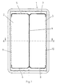
- the cap 1 shown in Fig. 1 is intended in the event of a crash tear open.
- the cap a Carrier layer 11 has an edge 12 and that over a cover layer 13 is provided for the carrier layer 11. Both are preferably made of plastic, which The material of the cover layer is softer than the material of the Support layer.
- the cover layer 13 has a continuous Surface while being on the underside in the invention Way is executed.
- the cover layer has in the tear area 4 - 8 a groove, into which one Section 11a of the carrier layer extends.
- the carrier layer has a slit in the tear-open area 4-8 on, i.e. the folding areas 2, 3 are in the carrier layer separated from each other. Extends into this slot a section 13a of the cover layer 13. Between the two Sections 11a and 13a have a tear-open edge 14. This runs in the present embodiment in Cross-section straight and extends almost through through the entire base and top layer.
- the thickness d of the cover layer 13 over the section 11a is preferably a few tenths of a millimeter and to the The ends of the tear areas 5 - 8 approx. One millimeter.
- the carrier layer 11 and the Cover layer 13 When inflated, the carrier layer 11 and the Cover layer 13 different due to uneven elasticity.
- the cover material tears over the reinforced section 11a of the carrier layer 11 and dissolves along the oblique tear-open edge 14 of the carrier material.
- the adhesion between the carrier and the top layer is however, on the other hand, so large that both when opening the Cover cap connected in the other areas remain so that the cover cap tears open completely.
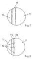
- FIG. 5 A modification of the exemplary embodiment in FIG. 4 is shown in FIG Fig. 5 shown.
- the carrier layer points in the area the tear-open edge 15 on bead-shaped reinforcements 16, 17.
- the Backing layer 11 has no slot in the area of the tear-open edge but a weakening of the material, so that a web 18 remains.
- the Both sides have been weakened.
- the reinforced one Section 13a of the cover layer 13 extends into the area of the carrier layer that has been slaughtered up to the web 18.
- the web has such a width that despite the different elasticity of the backing and top layer together with the top layer above the reinforced Section 11a tears open.
- the carrier layer 11 a slot which is bridged by webs 19, which extend from one side of the carrier layer 11 to the other Extend side.
- the reinforced section 13a is thus in 8 between the webs 19 can be seen.
Landscapes
- Engineering & Computer Science (AREA)
- Mechanical Engineering (AREA)
- Air Bags (AREA)
Abstract
Claims (12)
- Élément de recouvrement d'airbag constitué d'une couche de support et d'une couche de recouvrement présentant des élasticités différentes avec au moins une ligne de déchirement le long de laquelle l'élément de recouvrement d'airbag se déchire lorsque l'airbag se déploie, la couche de recouvrement dans la zone de la ligne de déchirement étant rendue moins solide au moyen d'une rainure et la couche de support s'étendant dans cette rainure,
caractérisé en ce que
la couche de recouvrement (13) présente une section (13a) dans la zone contiguë à la section (11a) de la couche de support (11) qui s'étend à l'intérieur de la rainure, laquelle section (13a) s'étend dans la couche de recouvrement, l'arête entre les sections (11a, 13a) des couches de support et de recouvrement (11, 13) qui s'étendent chacune dans l'autre couche consistant en une arête de déchirement (14, 15). - Élément de recouvrement d'airbag selon la revendication 1 caractérisé en ce que la couche de support (11) dans la zone de l'arête de déchirement (14) est moins solide que les autres zones et que la couche de recouvrement (13) s'étend dans la zone de moindre solidité.
- Élément de recouvrement d'airbag selon la revendication 1 ou 2 caractérisé en ce que la couche de support (11) dans la zone de l'arête de déchirement (14, 15) présente au moins une fente et que la couche de recouvrement (13) s'étend au moins en partie à l'intérieur de la fente.
- Élément de recouvrement d'airbag selon la revendication 3 caractérisé en ce que la fente est surmontée par des arcades (19) minces et étroites.
- Élément de recouvrement d'airbag selon la revendication 3 ou 4 caractérisé en ce que les arcades (19) ont une largeur maximale de 0,8 mm et qu'elles sont disposées selon des intervalles d'au moins 10 mm.
- Élément de recouvrement d'airbag selon au moins l'une des revendications précédentes caractérisé en ce que l'épaisseur (d) de la couche de recouvrement (13) située au-dessus de la section (11a) de la couche de support (11) qui s'étend dans la couche de recouvrement augmente aux extrémités des zones de déchirement.
- Élément de recouvrement d'airbag selon au moins l'une des revendications 3 à 6 caractérisé en ce qu'on a prévu au bord de la fente des renforcements (16, 17) en forme de bourrelet.
- Élément de recouvrement d'airbag selon au moins l'une des revendications précédentes caractérisé en ce que l'arête de déchirement (14, 15) par rapport à la surface de la couche de recouvrement et à la couche de support s'étend de biais dans cette zone.
- Élément de recouvrement d'airbag selon au moins l'une des revendications précédentes caractérisé en ce que l'arête de déchirement (14, 15) s'étend en section transversale en ligne droite, en ligne droite repliée ou en formant une courbure.
- Élément de recouvrement d'airbag selon au moins l'une des revendications précédentes caractérisé en ce que les couches de support et de recouvrement (11, 13) présentent une adhérence moins grande sur l'arête de déchirement (14, 15).
- Élément de recouvrement d'airbag selon au moins l'une des revendications précédentes caractérisé en ce qu'on utilise pour les couches de support et de recouvrement (11, 13) un matériau pour lequel l'adhérence opposée est réduite.
- Élément de recouvrement d'airbag selon au moins l'une des revendications précédentes caractérisé en ce que les couches de support et de recouvrement (11, 13) sont constituées en élastomères thermoplastiques.
Applications Claiming Priority (3)
| Application Number | Priority Date | Filing Date | Title |
|---|---|---|---|
| DE19718931A DE19718931C1 (de) | 1997-04-28 | 1997-04-28 | Airbagabdeckkappe aus Träger- und Deckschicht unterschiedlicher Elastizität |
| DE19718931 | 1997-04-28 | ||
| PCT/DE1998/000808 WO1998049033A1 (fr) | 1997-04-28 | 1998-03-13 | Element de recouvrement d'airbag constitue d'une couche de support et d'une couche de recouvrement presentant des elasticites differentes |
Publications (2)
| Publication Number | Publication Date |
|---|---|
| EP0979185A1 EP0979185A1 (fr) | 2000-02-16 |
| EP0979185B1 true EP0979185B1 (fr) | 2002-06-19 |
Family
ID=7828664
Family Applications (1)
| Application Number | Title | Priority Date | Filing Date |
|---|---|---|---|
| EP98925410A Expired - Lifetime EP0979185B1 (fr) | 1997-04-28 | 1998-03-13 | Element de recouvrement d'airbag constitue d'une couche de support et d'une couche de recouvrement presentant des elasticites differentes |
Country Status (7)
| Country | Link |
|---|---|
| US (1) | US6505850B2 (fr) |
| EP (1) | EP0979185B1 (fr) |
| JP (1) | JP2000512953A (fr) |
| BR (1) | BR9809324A (fr) |
| DE (1) | DE19718931C1 (fr) |
| ES (1) | ES2179502T3 (fr) |
| WO (1) | WO1998049033A1 (fr) |
Cited By (1)
| Publication number | Priority date | Publication date | Assignee | Title |
|---|---|---|---|---|
| WO2025153418A1 (fr) * | 2024-01-19 | 2025-07-24 | Dalphi Metal Espana, SLU | Capot de module pour un module de coussin de sécurité gonflable |
Families Citing this family (21)
| Publication number | Priority date | Publication date | Assignee | Title |
|---|---|---|---|---|
| DE10023646A1 (de) * | 2000-05-13 | 2001-11-15 | Bayerische Motoren Werke Ag | Abdeckung für den Beifahrer-Airbag eines Personenkraftwagens |
| US20040056382A1 (en) * | 2002-09-19 | 2004-03-25 | Shaner Kenneth W. | Method of molding a vehicle trim component |
| ATE399633T1 (de) * | 2003-09-25 | 2008-07-15 | Antolin Grupo Ing Sa | Verfahren zum einbringen einer schwächungslinie in eine airbagabdeckung mittels eines ultraschallhorns |
| DE602004014574D1 (de) * | 2003-09-30 | 2008-08-07 | Nihon Plast Co Ltd | Gassackabdeckung und Herstellungsverfahren dafür |
| KR100520551B1 (ko) * | 2003-10-10 | 2005-10-11 | 현대자동차주식회사 | 인비져블 에어백용 피에이비 도어 설계 방법 |
| US7780186B2 (en) * | 2004-09-21 | 2010-08-24 | Tk Holdings Inc. | Airbag module cover |
| JP2006290305A (ja) * | 2005-04-14 | 2006-10-26 | Nippon Plast Co Ltd | 自動車用内装パネル |
| JP4831999B2 (ja) * | 2005-05-31 | 2011-12-07 | 三光合成株式会社 | 車両用エアーバック装置及びエアーバックカバー |
| US7384061B2 (en) | 2005-07-14 | 2008-06-10 | International Automotive Components Group North America, Inc. | Trim panel and a method of manufacture |
| JP4861682B2 (ja) * | 2005-11-08 | 2012-01-25 | 日本プラスト株式会社 | インストルメントパネル |
| DE202006013133U1 (de) | 2006-08-23 | 2006-11-02 | Takata-Petri Ag | Gassackabdeckung |
| US7748732B2 (en) * | 2006-11-07 | 2010-07-06 | Autoliv Asp, Inc. | Airbag cover tear seam |
| DE102008011519A1 (de) * | 2008-02-25 | 2009-09-03 | Faurecia Innenraum Systeme Gmbh | Innenverkleidungsteil |
| JP4535183B2 (ja) * | 2008-09-04 | 2010-09-01 | トヨタ自動車株式会社 | 車両用ニーエアバッグ装置 |
| JP2010173505A (ja) * | 2009-01-30 | 2010-08-12 | Toyoda Gosei Co Ltd | 助手席用エアバッグ装置 |
| DE102009048893B4 (de) * | 2009-10-09 | 2013-09-12 | Lisa Dräxlmaier GmbH | Airbagabdeckung |
| US8783711B2 (en) * | 2012-12-17 | 2014-07-22 | Chrysler Group Llc | Low mass passenger airbag design |
| JP6245905B2 (ja) * | 2013-09-12 | 2017-12-13 | ダイキョーニシカワ株式会社 | エアバッグドア部を有する車両用内装品 |
| DE102014103501A1 (de) | 2014-03-14 | 2015-09-17 | Euwe Eugen Wexler Gmbh | Verfahren zur Herstellung eines Kunststoffbauteils mittels eines Spritzgießprozesses |
| JP6254479B2 (ja) * | 2014-04-11 | 2017-12-27 | ダイキョーニシカワ株式会社 | エアバッグドア部を有する車両用内装品 |
| CN120166972A (zh) * | 2022-10-06 | 2025-06-17 | 延锋国际汽车技术有限公司 | 用于车辆内部的部件 |
Family Cites Families (22)
| Publication number | Priority date | Publication date | Assignee | Title |
|---|---|---|---|---|
| US3756617A (en) * | 1969-09-15 | 1973-09-04 | Eaton Corp | Safety apparatus |
| US4989896A (en) * | 1988-10-17 | 1991-02-05 | Tip Engineering Group, Inc. | Double door closure for an air bag deployment opening |
| JPH02303949A (ja) * | 1989-05-17 | 1990-12-17 | Nippon Plast Co Ltd | エアバックのカバー体 |
| US5082310A (en) * | 1989-11-06 | 1992-01-21 | Tip Engineering Group, Inc. | Arrangement for providing an air bag deployment opening |
| JP2956137B2 (ja) * | 1990-06-20 | 1999-10-04 | タカタ株式会社 | エアバッグ装置のモジュールカバー |
| US5316822A (en) * | 1991-07-23 | 1994-05-31 | Nihon Plast Co., Ltd. | Cover for vehicular air bag |
| JP2896256B2 (ja) * | 1991-10-18 | 1999-05-31 | 日本プラスト株式会社 | エアバッグ収納カバー体 |
| JPH0651024A (ja) | 1992-07-31 | 1994-02-25 | Nec Corp | テスト回路 |
| US5335935A (en) * | 1992-08-31 | 1994-08-09 | Plastic Mold Technology Incorporated | Air bag cover/molded article with integral cover layer of leather |
| GB2270884B (en) * | 1992-09-29 | 1995-11-22 | Autoliv Dev | Improvements in or relating to an air-bag cover |
| US5443777A (en) * | 1992-12-04 | 1995-08-22 | Davidson Textron Inc. | Method for producing an invisible tear seam for an air bag deployment opening cover |
| GB9315047D0 (en) * | 1993-07-20 | 1993-09-01 | Klippan Autoliv Snc | Improvements in or relating to a cover for an air-bag |
| GB2287226B (en) * | 1994-03-10 | 1997-05-14 | Autoliv Dev | Improvements in or relating to an air-bag arrangement |
| US5536037A (en) | 1994-11-18 | 1996-07-16 | Trw Vehicle Safety Systems Inc. | Deployment door for use in a vehicle occupant restraint apparatus |
| DE19516230C2 (de) * | 1995-05-03 | 1999-04-01 | Eldra Kunststofftechnik Gmbh | Airbag-Abdeckung sowie Verfahren zu seiner Herstellung |
| EP0749872B1 (fr) * | 1995-06-21 | 2003-04-23 | Toyoda Gosei Co., Ltd. | Couvercle pour sac gonflable et procédé de fabrication |
| JP3201243B2 (ja) * | 1995-12-12 | 2001-08-20 | 豊田合成株式会社 | エアバッグ用蓋体付き自動車内装品 |
| JPH09156445A (ja) * | 1995-12-12 | 1997-06-17 | Toyoda Gosei Co Ltd | エアバッグカバー |
| US5741025A (en) * | 1996-05-22 | 1998-04-21 | Ks Centoco Ltd. | Integral steering wheel and air bag assembly |
| DE19626416A1 (de) * | 1996-07-01 | 1998-01-08 | Takata Europ Gmbh | Airbagmodul-Abdeckkappe |
| DE19653797A1 (de) * | 1996-12-21 | 1998-06-25 | Mst Automotive Gmbh | Abdeckung für ein Airbag-Modul |
| US5997030A (en) * | 1997-03-19 | 1999-12-07 | Lear Automotive Dearborn, Inc. | Vehicle instrument panel with seamless airbag cover |
-
1997
- 1997-04-28 DE DE19718931A patent/DE19718931C1/de not_active Expired - Fee Related
-
1998
- 1998-03-13 ES ES98925410T patent/ES2179502T3/es not_active Expired - Lifetime
- 1998-03-13 WO PCT/DE1998/000808 patent/WO1998049033A1/fr not_active Ceased
- 1998-03-13 EP EP98925410A patent/EP0979185B1/fr not_active Expired - Lifetime
- 1998-03-13 US US09/403,471 patent/US6505850B2/en not_active Expired - Fee Related
- 1998-03-13 BR BR9809324-0A patent/BR9809324A/pt not_active Application Discontinuation
- 1998-03-13 JP JP10546462A patent/JP2000512953A/ja active Pending
Cited By (1)
| Publication number | Priority date | Publication date | Assignee | Title |
|---|---|---|---|---|
| WO2025153418A1 (fr) * | 2024-01-19 | 2025-07-24 | Dalphi Metal Espana, SLU | Capot de module pour un module de coussin de sécurité gonflable |
Also Published As
| Publication number | Publication date |
|---|---|
| DE19718931C1 (de) | 1998-08-06 |
| US20020024199A1 (en) | 2002-02-28 |
| WO1998049033A1 (fr) | 1998-11-05 |
| BR9809324A (pt) | 2000-07-04 |
| US6505850B2 (en) | 2003-01-14 |
| JP2000512953A (ja) | 2000-10-03 |
| EP0979185A1 (fr) | 2000-02-16 |
| ES2179502T3 (es) | 2003-01-16 |
Similar Documents
| Publication | Publication Date | Title |
|---|---|---|
| EP0979185B1 (fr) | Element de recouvrement d'airbag constitue d'une couche de support et d'une couche de recouvrement presentant des elasticites differentes | |
| DE19581573C1 (de) | Eine Airbag-Anordnung | |
| EP0818359B1 (fr) | Couvercle pour module de coussin gonflable | |
| DE69001798T2 (de) | Schraubverschlusskappe mit originalitaetsband. | |
| WO1990008667A1 (fr) | Dispositif de fixation d'un panneau amovible sur le cadre d'un toit coulissant ou d'un toit ouvrant coulissant | |
| DE4115904C2 (de) | Abdeckung zur Aufnahme eines Gassacks | |
| DE19710246A1 (de) | Element und Verfahren zum Einsetzen des Elements in ein plattenförmiges Bauteil | |
| WO1986003721A1 (fr) | Couvercle de fermeture en plastique | |
| DE2832807C2 (de) | Deckel für einen Behälter und Verfahren zu dessen Herstellung | |
| DE19653797A1 (de) | Abdeckung für ein Airbag-Modul | |
| EP0642940A1 (fr) | Véhicule automobile avec au moins une porte | |
| EP0521410A1 (fr) | Emballage de vente | |
| DE602004004327T2 (de) | Gassackabdeckung | |
| DE3607402C2 (fr) | ||
| EP0451102A1 (fr) | Capsule en matière plastique | |
| DE10032971A1 (de) | Aus mindestens zwei Säulenabschnitten bestehende Mittelsäule einer Kraftfahrzeugkarosserie | |
| DE3326082C2 (de) | Verfahren zur Bildung einer Schieberschachtel und danach hergestellte Schieberschachtel | |
| DE3204974C2 (de) | Dose | |
| DE19701106B4 (de) | Verstärkte Abdeckkappe für eine Airbaganordnung | |
| EP0967127B1 (fr) | Planche de bord pour un véhicule automobile | |
| EP1241082B1 (fr) | Véhicule automobile avec au moins un capot , spécialement pour compartiment moteur ou bagages | |
| WO2007134880A1 (fr) | Cache airbag | |
| DE3307008C2 (fr) | ||
| DE4305138A1 (en) | Safety closure for bottles etc.with cap and safety ring with break line - has recesses between sectors formed around flanged lower edge of safety ring | |
| EP1392551A1 (fr) | Dispositif pour recouvrir un coussin gonflable de securite et son procede de production |
Legal Events
| Date | Code | Title | Description |
|---|---|---|---|
| PUAI | Public reference made under article 153(3) epc to a published international application that has entered the european phase |
Free format text: ORIGINAL CODE: 0009012 |
|
| 17P | Request for examination filed |
Effective date: 19991109 |
|
| AK | Designated contracting states |
Kind code of ref document: A1 Designated state(s): ES FR GB |
|
| GRAG | Despatch of communication of intention to grant |
Free format text: ORIGINAL CODE: EPIDOS AGRA |
|
| 17Q | First examination report despatched |
Effective date: 20010723 |
|
| GRAG | Despatch of communication of intention to grant |
Free format text: ORIGINAL CODE: EPIDOS AGRA |
|
| GRAH | Despatch of communication of intention to grant a patent |
Free format text: ORIGINAL CODE: EPIDOS IGRA |
|
| RAP1 | Party data changed (applicant data changed or rights of an application transferred) |
Owner name: TAKATA-PETRI AG |
|
| GRAH | Despatch of communication of intention to grant a patent |
Free format text: ORIGINAL CODE: EPIDOS IGRA |
|
| GRAA | (expected) grant |
Free format text: ORIGINAL CODE: 0009210 |
|
| AK | Designated contracting states |
Kind code of ref document: B1 Designated state(s): ES FR GB |
|
| REG | Reference to a national code |
Ref country code: GB Ref legal event code: FG4D Free format text: NOT ENGLISH |
|
| GBT | Gb: translation of ep patent filed (gb section 77(6)(a)/1977) |
Effective date: 20020906 |
|
| ET | Fr: translation filed | ||
| REG | Reference to a national code |
Ref country code: ES Ref legal event code: FG2A Ref document number: 2179502 Country of ref document: ES Kind code of ref document: T3 |
|
| PLBE | No opposition filed within time limit |
Free format text: ORIGINAL CODE: 0009261 |
|
| STAA | Information on the status of an ep patent application or granted ep patent |
Free format text: STATUS: NO OPPOSITION FILED WITHIN TIME LIMIT |
|
| 26N | No opposition filed |
Effective date: 20030320 |
|
| PGFP | Annual fee paid to national office [announced via postgrant information from national office to epo] |
Ref country code: GB Payment date: 20040225 Year of fee payment: 7 |
|
| PGFP | Annual fee paid to national office [announced via postgrant information from national office to epo] |
Ref country code: FR Payment date: 20040318 Year of fee payment: 7 |
|
| PGFP | Annual fee paid to national office [announced via postgrant information from national office to epo] |
Ref country code: ES Payment date: 20040324 Year of fee payment: 7 |
|
| PG25 | Lapsed in a contracting state [announced via postgrant information from national office to epo] |
Ref country code: GB Free format text: LAPSE BECAUSE OF NON-PAYMENT OF DUE FEES Effective date: 20050313 |
|
| PG25 | Lapsed in a contracting state [announced via postgrant information from national office to epo] |
Ref country code: ES Free format text: LAPSE BECAUSE OF NON-PAYMENT OF DUE FEES Effective date: 20050314 |
|
| GBPC | Gb: european patent ceased through non-payment of renewal fee |
Effective date: 20050313 |
|
| PG25 | Lapsed in a contracting state [announced via postgrant information from national office to epo] |
Ref country code: FR Free format text: LAPSE BECAUSE OF NON-PAYMENT OF DUE FEES Effective date: 20051130 |
|
| REG | Reference to a national code |
Ref country code: FR Ref legal event code: ST Effective date: 20051130 |
|
| REG | Reference to a national code |
Ref country code: ES Ref legal event code: FD2A Effective date: 20050314 |