EP0982261A2 - Endloses Fördersystem mit höherer Geschwindigkeit - Google Patents
Endloses Fördersystem mit höherer Geschwindigkeit Download PDFInfo
- Publication number
- EP0982261A2 EP0982261A2 EP99306387A EP99306387A EP0982261A2 EP 0982261 A2 EP0982261 A2 EP 0982261A2 EP 99306387 A EP99306387 A EP 99306387A EP 99306387 A EP99306387 A EP 99306387A EP 0982261 A2 EP0982261 A2 EP 0982261A2
- Authority
- EP
- European Patent Office
- Prior art keywords
- speed
- tread
- conveying
- moving
- moving slope
- Prior art date
- Legal status (The legal status is an assumption and is not a legal conclusion. Google has not performed a legal analysis and makes no representation as to the accuracy of the status listed.)
- Withdrawn
Links
- 230000007246 mechanism Effects 0.000 claims abstract description 21
- 230000035939 shock Effects 0.000 abstract description 15
- 230000001133 acceleration Effects 0.000 abstract description 7
- 229910052751 metal Inorganic materials 0.000 description 8
- 239000002184 metal Substances 0.000 description 8
- 229910052755 nonmetal Inorganic materials 0.000 description 5
- 238000000034 method Methods 0.000 description 3
- 229920001875 Ebonite Polymers 0.000 description 2
- XEEYBQQBJWHFJM-UHFFFAOYSA-N Iron Chemical compound [Fe] XEEYBQQBJWHFJM-UHFFFAOYSA-N 0.000 description 2
- 239000000463 material Substances 0.000 description 2
- 239000004033 plastic Substances 0.000 description 2
- 229920003023 plastic Polymers 0.000 description 2
- 229920001343 polytetrafluoroethylene Polymers 0.000 description 2
- 239000004810 polytetrafluoroethylene Substances 0.000 description 2
- 229910001018 Cast iron Inorganic materials 0.000 description 1
- 230000001154 acute effect Effects 0.000 description 1
- 229910052782 aluminium Inorganic materials 0.000 description 1
- XAGFODPZIPBFFR-UHFFFAOYSA-N aluminium Chemical compound [Al] XAGFODPZIPBFFR-UHFFFAOYSA-N 0.000 description 1
- 210000001520 comb Anatomy 0.000 description 1
- 230000000694 effects Effects 0.000 description 1
- 229910052742 iron Inorganic materials 0.000 description 1
- 238000012423 maintenance Methods 0.000 description 1
- 238000004519 manufacturing process Methods 0.000 description 1
- -1 polytetrafluoroethylene Polymers 0.000 description 1
- 238000010791 quenching Methods 0.000 description 1
- 229920005989 resin Polymers 0.000 description 1
- 239000011347 resin Substances 0.000 description 1
- 238000005096 rolling process Methods 0.000 description 1
- 230000007704 transition Effects 0.000 description 1
Images


Classifications
-
- B—PERFORMING OPERATIONS; TRANSPORTING
- B66—HOISTING; LIFTING; HAULING
- B66B—ELEVATORS; ESCALATORS OR MOVING WALKWAYS
- B66B21/00—Kinds or types of escalators or moving walkways
- B66B21/02—Escalators
- B66B21/025—Escalators of variable speed type
Definitions
- the present invention relates to a conveying system for the purpose of increasing the speed of a continuous conveying apparatus, and contributes to efficient operation of a moving walk, a moving slope and an escalator.
- An object of the present invention is to secure a transition region sufficient in function and strength between a getting on/off area and a high-speed running element.
- a high-speed continuous conveying system comprising:
- a limited angle of inclination for a moving slope depends on the material of a tread.
- a limited inclination angle for a surface of metal such as light metal and cast iron is standardized as 12°, and that for a surface of nonmetal such as hard rubber and plastics is standardized as 15°.
- an angle between the sloping tread of a high-speed running member, which is a main traveling member, and a relatively low-speed sloping tread on the getting-on/off area becomes the sum of inclination angles of both slopes at the transferring area, so that a small belt pulley or a small chain pulley of appropriate size can be located. Further, there are provided a free running tread and a fixed bridge that enable smooth transfer in the getting-on/off area.
- the magnitude of shock is equal to a product of mass and acceleration of the passenger. Even if the mass is constant, the acceleration changes complicatedly. Considering an average acceleration, however, a criterion for the magnitude of shock can be obtained. As the actual method, it is considered that the shock is minimized if speeds of the respective treads are determined so that the average acceleration in each transfer are equal. In FIG.
- Equation (1) is a newly found important equation. If a speed train of the tread faces takes the values that substantially accord with this equation, a tread train with low shock is realized.
- N small, a passenger may transfer by striding over between the different-speed treads.
- a free rotating roller may be interposed at an intermediate position of a bridge between the different-speed treads so that the transfer is performed easily and automatically.
- the tread is provided with longitudinal grooves for safety, and the comb of the getting-on/off section and the both combs, front and rear, of the bridge fit in the grooves.
- a passenger advances, he/she steps over the comb and bridge from the low-speed section to the medium-speed section, and the medium-speed section to the high-speed section along with his/her inertia, by which the transfer is made safely.
- the inclination of the tread is changed gradually to an allowable inclination angle, by which smooth traveling is made possible.
- a tread with a small speed difference is provided between the treads, and the sum of the longitudinal widths of the bridges before and behind the tread and the longitudinal width of the free tread is made approximately equal to the longitudinal length of shoe of the passenger, by which the slip and shock can be relieved.
- the heel lies on the low-speed side, but the toe lies on the free moving side. Therefore, the free moving side is frictionally driven at the low speed.
- the toe rides on the high-speed side, and the heel goes away from the low-speed tread and rides on the free tread.
- the heel transfers from the low-speed free tread to the high-speed side, by which the transfer is completed. If the above-described process is carried out relatively gradually, the slip and shock can be held within the allowable limit.
- the passenger transfers from high speed to low speed.
- the heel goes away from the high-speed tread and rides on the free tread.
- the heel also rides on the low-speed tread, by which the transfer is completed. If this process is carried out gradually, both of the slip and shock scarcely occur and are tolerable.
- a free rotating roller is suitable for the reason of space.
- the tread on the getting-on/off side two materials are used: a metal such as iron and aluminum, and a macro molecular nonmetal such as hard rubber and plastics.
- a metal such as iron and aluminum
- a macro molecular nonmetal such as hard rubber and plastics.
- the limited inclination angle of the former is standardized to be 12°
- the limited inclination angle of the latter is standardized to be 15°. Therefore, the tread having an inclination angle of 12° or smaller with respect to the horizontal getting-on/off section may be a metal surface, but the tread having an inclination angle larger than 12° and not larger than 15° must be a macro molecular nonmetal surface.
- the tread having an inclination angle of 12° or smaller may be made of a metal, and a metal plate installed to an extending portion on one side of a link of a conveying roller chain is made a tread.
- the tread having an inclination angle from 12° to 15° uses a toothed belt made of macro molecular nonmetal or the aforementioned metal plate of the conveying roller chain which is coated with macro molecular nonmetal.
- a passenger transfers from a downstairs floor surface F to a slope tread face 30 of a high-speed running step train 3 through a slope tread face 10 of a low-speed toothed belt unit 1 and a slope tread face 20 of a medium-speed toothed belt unit 2.
- Each of the tread faces has a longitudinal grooves into which a comb fits.
- the belt units 1, 2 have a small belt pulley 11, 21, a large belt pulley 12, 22, and an idler wheel 13, 23, respectively.
- a slope angel ⁇ 1 is set to be a maximum angle of 15°
- slope faces 10 and 20 are guided arcuately by guide members 16 and 26, respectively, and the slope angle is changed from 0° to 7.5° and from 7.5° to 15°, respectively.
- the slope angle ⁇ 1 of a medium-speed tread 20 is set to be the maximum value of 15°
- the slope angle ⁇ 2 of a high-speed tread 30 is set to be the maximum value of 12°
- an acute angle between the treads 20 and 30 is 27°. Therefore, a space enough to contain a small belt pulley 21 located near a region of transfer from the tread 20 to the tread 30 can be secured.
- bridges B12 and B23 each having comb teeth at both of front and rear ends, are provided to abut the tread.
- free rotating rollers 4 and 5 may be provided. The free rotating rollers 4 and 5 project slightly through slits formed in the bridge surface, and come into contact with the footwear by means of rolling friction to receive the load of the passenger.
- the passenger may stride over or leave oneself to the movement of the tread utilizing the passenger's own inertia. To minimize the shock at this time, the tread speed should obey the equation (1).
- V2 and V3 are obtained as V2 ⁇ 42.4 m/min and V3 ⁇ 52.0 m/min.
- the equation (1) is applied by approximately regarding that V2cos ⁇ 1 ⁇ V2 and V3cos ⁇ 2 ⁇ V3, and a correction is made experimentally, if necessary.
- the moving handrails denoted by reference numerals 61, 62 and 63 are provided corresponding to the treads 10, 20 and 30, respectively.
- the large belt pulleys 12 and 22 can be driven by an ordinary transmitting mechanism, so that the illustration and description thereof are omitted.
- the constitution near the upstairs floor getting-on/off portion is the same as that on the downstairs floor except that sequence of arrangement of components is reverse to that on the downstairs floor. Therefore, the corresponding element is denoted by adding a dash to the reference numeral of each element, and the description is omitted.
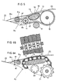
- FIGS. 3a and 3b A typical constitution of a conveying roller chain equipped with upper plates functioning as treads is shown in FIGS. 3a and 3b.
- Treads ns, nt each having longitudinal grooves are fixed to the upper plates np, nq, and rollers to be driven by a sprocket 7n are guided by an arcuate guide face Gn.
- a mechanism having the above constitution is called a roller chain unit Un.
- the chain unit Un is provided with the driving sprocket 7n and an idler gear 8n.
- a bridge 12 and a free rotating roller R12 whose top portion projects through a central slit formed on the bridge B12.
- a bridge B2b and a free rotating roller R2b Between the roller chain unit U2 and the toothed belt unit B are provided a bridge B2b and a free rotating roller R2b.
- Between the toothed belt unit B and the high-speed running slope tread H are provided a bridge Bbh and a free rotating roller Rbh.
- Moving handrails are provided corresponding to the roller chain units U1 and U2, the toothed belt unit B, and the high-speed running slope tread H.
- the running speeds in the typical case are as given in the table below.
- FIG. 4 shows an example in which the present invention is applied to a moving walk.
- toothed belt units are used in this example, roller chain units may be used.
- the moving handrails are omitted in the drawing.
- reference characters 0S and 0S' denote floor surfaces
- 1S and 1S' denote low-speed getting-on/off treads
- 2S and 2S' denote medium-speed treads
- 3S and 3S' denote high-speed slope treads
- B12, B12', B23 and B23' denote bridges with free rotating rollers.
- FIGS. 5, 6a and 6b show examples of the single-unit system.
- FIG. 5 shows an example in which a toothed belt unit is used
- FIGS. 6a and 6b show an example in which a roller chain unit is used.
- FIG. 6a is a side view of a conveying unit and the vicinity thereof
- FIG. 6b is a plan view substantially parallel to treads of the conveying unit. Reference numerals of the parts are the same as those used in FIGS. 1 and 3. However, in FIG.
- a supporting toothed belt 17 engaged opposingly with the conveying belt and a support member 18 having a guide face 19 for guiding and supporting the supporting belt are used as a guide member for supporting the conveying belt with the tread 10.
- the supporting belt 17 is wound and circulated around the support member 18 (the lower half thereof has an arcuate cross section). With this arrangement, a life of the conveying belt is elongated.
- a high-speed escalator, a moving walk, and a moving slope that is simple in structure with low shock in transferring can be realized.
Landscapes
- Escalators And Moving Walkways (AREA)
Applications Claiming Priority (2)
| Application Number | Priority Date | Filing Date | Title |
|---|---|---|---|
| JP26718298 | 1998-08-18 | ||
| JP26718298 | 1998-08-18 |
Publications (2)
| Publication Number | Publication Date |
|---|---|
| EP0982261A2 true EP0982261A2 (de) | 2000-03-01 |
| EP0982261A3 EP0982261A3 (de) | 2002-02-13 |
Family
ID=17441258
Family Applications (1)
| Application Number | Title | Priority Date | Filing Date |
|---|---|---|---|
| EP99306387A Withdrawn EP0982261A3 (de) | 1998-08-18 | 1999-08-13 | Endloses Fördersystem mit höherer Geschwindigkeit |
Country Status (2)
| Country | Link |
|---|---|
| US (1) | US6439365B1 (de) |
| EP (1) | EP0982261A3 (de) |
Cited By (2)
| Publication number | Priority date | Publication date | Assignee | Title |
|---|---|---|---|---|
| EP1153873A4 (de) * | 1998-12-11 | 2002-10-30 | Fujitec Kk | Rollsteig mit variabler geschwindigkeit und verfahren zu seinem entwurf |
| EP1468951A4 (de) * | 2002-01-22 | 2006-11-29 | Mitsubishi Electric Corp | Hochgeschwindigkeitsfahrtreppe mit geneigtem teil |
Families Citing this family (4)
| Publication number | Priority date | Publication date | Assignee | Title |
|---|---|---|---|---|
| US7210569B1 (en) * | 2004-02-09 | 2007-05-01 | Tarpaulin.Com, Inc. | Transfer device for conveyor belt |
| ES2334322B1 (es) * | 2009-07-03 | 2010-12-27 | Tyhssenkrupp Elevator Innovation Center, S.A. | Rampa para transporte de personas y/o mercancias. |
| WO2016141058A1 (en) * | 2015-03-02 | 2016-09-09 | Yuksel Edip | System of hexagonal building units and escalators or moving walkways used therein |
| WO2025188893A1 (en) * | 2024-03-06 | 2025-09-12 | Beltways, Inc. | Dynamic comb for conveyance systems for moving people or objects |
Family Cites Families (16)
| Publication number | Priority date | Publication date | Assignee | Title |
|---|---|---|---|---|
| US2936873A (en) * | 1956-06-21 | 1960-05-17 | Sol H Seidman | Load transfer system |
| US3150757A (en) * | 1961-02-13 | 1964-09-29 | Hitachi Ltd | Moving sidewalk |
| US3698535A (en) * | 1970-11-04 | 1972-10-17 | Goodyear Tire & Rubber | Passenger conveyor landing |
| JPH03186590A (ja) | 1989-12-15 | 1991-08-14 | Kiyoshi Endo | 速度可変エスカレータおよび移動歩道ユニット |
| FR2675135B1 (fr) * | 1991-04-12 | 1993-08-06 | Patin Pierre | Dispositif de transport, notamment a element transporteur a vitesse elevee. |
| JP3197582B2 (ja) | 1991-07-30 | 2001-08-13 | 東レ・ダウコーニング・シリコーン株式会社 | シリコーンエラストマーフォームの製造方法及びその製造装置 |
| JP2637313B2 (ja) | 1991-08-29 | 1997-08-06 | 株式会社東芝 | 伝送路2重化バス型伝送システム |
| DE4238252C2 (de) * | 1992-11-12 | 1994-08-18 | Woodway Ag | Zahn- und Keilriemeneinrichtung für Laufbänder |
| JPH07172747A (ja) | 1993-12-20 | 1995-07-11 | Masao Kubota | 搬送装置システム |
| CA2155868A1 (en) * | 1993-12-20 | 1995-06-29 | Masao Kubota | Connected conveyor machine |
| DE4442982C2 (de) * | 1994-12-02 | 1997-12-04 | Heidelberger Druckmasch Ag | Papiertransportvorrichtung |
| US5950797A (en) * | 1996-02-29 | 1999-09-14 | Kone Oy | People mover and drive apparatus |
| FR2747664B1 (fr) * | 1996-04-23 | 1998-06-05 | Mediterranee Const Ind | Dispositif de transfert, en particulier pour pietons, entre deux elements de transport disposes en prolongement l'un de l'autre et transporteur equipe d'un tel dispositif |
| JP3186590B2 (ja) | 1996-07-05 | 2001-07-11 | ジェイエスアール株式会社 | 成形用金型、及び成形方法 |
| MY119352A (en) * | 1997-01-17 | 2005-05-31 | Inventio Ag | Moving walkway for passengers |
| EP0854108B1 (de) * | 1997-01-17 | 2003-04-09 | Inventio Ag | Personenförderband |
-
1999
- 1999-08-13 EP EP99306387A patent/EP0982261A3/de not_active Withdrawn
- 1999-08-17 US US09/375,368 patent/US6439365B1/en not_active Expired - Fee Related
Cited By (3)
| Publication number | Priority date | Publication date | Assignee | Title |
|---|---|---|---|---|
| EP1153873A4 (de) * | 1998-12-11 | 2002-10-30 | Fujitec Kk | Rollsteig mit variabler geschwindigkeit und verfahren zu seinem entwurf |
| US6604621B1 (en) | 1998-12-11 | 2003-08-12 | Fujitec Co., Ltd. | Variable-speed moving sidewalk and method of designing it |
| EP1468951A4 (de) * | 2002-01-22 | 2006-11-29 | Mitsubishi Electric Corp | Hochgeschwindigkeitsfahrtreppe mit geneigtem teil |
Also Published As
| Publication number | Publication date |
|---|---|
| EP0982261A3 (de) | 2002-02-13 |
| US6439365B1 (en) | 2002-08-27 |
Similar Documents
| Publication | Publication Date | Title |
|---|---|---|
| KR0147083B1 (ko) | 가감속식 움직이는 보도 | |
| US5881859A (en) | Escalator handrail drive mechanism | |
| EP0982261A2 (de) | Endloses Fördersystem mit höherer Geschwindigkeit | |
| JPS62185692A (ja) | 走行速度が変化するエスカレ−タ | |
| US5595278A (en) | Pallet for a conveyor | |
| KR100204840B1 (ko) | 가변속식 컨베이어 | |
| USRE27439E (en) | Inclined moving walkway arrangement | |
| EP0685421A1 (de) | Verbundene fördereinrichtung | |
| EP0980843A2 (de) | Durchgehender und wendelbarer Beförderer | |
| US7571797B2 (en) | Newel guide for supporting a handrail traveling over a newel | |
| US3621980A (en) | Conveyors | |
| JP2000128467A (ja) | 高速連続搬送装置システム | |
| JP2000318961A (ja) | 加減速式動く歩道用手摺 | |
| JP2845747B2 (ja) | 動く歩道 | |
| JPH1059668A (ja) | 可変速型乗客コンベヤ | |
| JP2581854B2 (ja) | マンコンベア装置 | |
| JP2000229774A (ja) | 可変速型乗客コンベアおよびその運転方法 | |
| JPH11286382A (ja) | 可変速型乗客コンベヤ | |
| JPH07237874A (ja) | 動く歩道のハンドレール駆動装置 | |
| JP3817684B2 (ja) | 複数駆動源乗客コンベア | |
| WO2003062118A1 (en) | Sloped part high-speed escalator | |
| JP3613047B2 (ja) | 動く歩道の乗客案内装置 | |
| JPH07172747A (ja) | 搬送装置システム | |
| JPH0986845A (ja) | 可変速式動く歩道における手摺装置 | |
| JP2719591B2 (ja) | エスカレータ |
Legal Events
| Date | Code | Title | Description |
|---|---|---|---|
| PUAI | Public reference made under article 153(3) epc to a published international application that has entered the european phase |
Free format text: ORIGINAL CODE: 0009012 |
|
| AK | Designated contracting states |
Kind code of ref document: A2 Designated state(s): AT BE CH CY DE DK ES FI FR GB GR IE IT LI LU MC NL PT SE |
|
| AX | Request for extension of the european patent |
Free format text: AL;LT;LV;MK;RO;SI |
|
| PUAL | Search report despatched |
Free format text: ORIGINAL CODE: 0009013 |
|
| AK | Designated contracting states |
Kind code of ref document: A3 Designated state(s): AT BE CH CY DE DK ES FI FR GB GR IE IT LI LU MC NL PT SE |
|
| AX | Request for extension of the european patent |
Free format text: AL;LT;LV;MK;RO;SI |
|
| STAA | Information on the status of an ep patent application or granted ep patent |
Free format text: STATUS: THE APPLICATION IS DEEMED TO BE WITHDRAWN |
|
| AKX | Designation fees paid | ||
| 18D | Application deemed to be withdrawn |
Effective date: 20020401 |
|
| REG | Reference to a national code |
Ref country code: DE Ref legal event code: 8566 |