EP0987149A2 - Couvercle pour coussin de sécurité - Google Patents
Couvercle pour coussin de sécurité Download PDFInfo
- Publication number
- EP0987149A2 EP0987149A2 EP99113620A EP99113620A EP0987149A2 EP 0987149 A2 EP0987149 A2 EP 0987149A2 EP 99113620 A EP99113620 A EP 99113620A EP 99113620 A EP99113620 A EP 99113620A EP 0987149 A2 EP0987149 A2 EP 0987149A2
- Authority
- EP
- European Patent Office
- Prior art keywords
- tear seam
- airbag cover
- seam segment
- segment
- tear
- Prior art date
- Legal status (The legal status is an assumption and is not a legal conclusion. Google has not performed a legal analysis and makes no representation as to the accuracy of the status listed.)
- Granted
Links
Images


Classifications
-
- B—PERFORMING OPERATIONS; TRANSPORTING
- B60—VEHICLES IN GENERAL
- B60R—VEHICLES, VEHICLE FITTINGS, OR VEHICLE PARTS, NOT OTHERWISE PROVIDED FOR
- B60R21/00—Arrangements or fittings on vehicles for protecting or preventing injuries to occupants or pedestrians in case of accidents or other traffic risks
- B60R21/02—Occupant safety arrangements or fittings, e.g. crash pads
- B60R21/16—Inflatable occupant restraints or confinements designed to inflate upon impact or impending impact, e.g. air bags
- B60R21/20—Arrangements for storing inflatable members in their non-use or deflated condition; Arrangement or mounting of air bag modules or components
- B60R21/215—Arrangements for storing inflatable members in their non-use or deflated condition; Arrangement or mounting of air bag modules or components characterised by the covers for the inflatable member
- B60R21/2165—Arrangements for storing inflatable members in their non-use or deflated condition; Arrangement or mounting of air bag modules or components characterised by the covers for the inflatable member characterised by a tear line for defining a deployment opening
Definitions
- This invention pertains to the field of airbag covers, such as are used in automobile steering wheels.
- Tear seams in airbag covers tear upon the deployment of an airbag.
- Conventional airbag covers feature tear seams which consist of a groove in the airbag cover. Because the tear seam is of a reduced thickness, the tear seam can be visible as an indented line in the airbag cover. Conversely, tear seams may be hidden from view by being placed in the side of the airbag cover that it is not visible to a vehicle occupant.
- the grooves which create conventional tear seams have substantially constant depths. While this tensile strength is weaker than that of the remaining area of the airbag cover such that the tear seam tears before any other part of the airbag cover, the tearing of the tear seam is not easily controllable. This could result in less than optimal deployment of the airbag.
- One advantage of the present invention is that variation of the transverse layer's length, width and angle permits the tearing of the tear seam to be controllable. Additionally, fatigue failure can be prevented at locations along the tear seam, which receive considerable stress.
- Another advantage of the present invention is the reduction in material mass in a portion of the back side of the airbag cover.
- Another advantage of the present invention is that the tear seam, unlike conventional tear seams, enables an emblem to be mounted on the front side of the airbag cover.
- the tear seam 12 is more clearly shown in FIGS. 3, 4, 5, 8, 9 and 10.
- the airbag cover 10 has a tear seam 12 therein.
- the tear seam 12 defines first and second deployment doors 70, 74 in the airbag cover 10.
- the tear seam 12 tears and deployment doors open. The airbag 16 is thus deployed through the airbag cover.
- the airbag cover 10 and deployment doors 70, 74 are in a plane 18 that has a high radius of curvature or is essentially flat prior to the deployment of the airbag 16.
- the airbag cover 10 further comprises first and second hinges 48, 50 about which the deployment doors pivot open upon the deployment of the airbag 16.
- first and second hinges 48, 50 about which the deployment doors pivot open upon the deployment of the airbag 16.
- the hinges prevent the deployment doors from completely detaching from the airbag cover.
- the airbag cover 10 has front and back sides 22, 24.
- front refers to a side or surface of an airbag cover that faces towards a vehicle occupant when the airbag cover is installed in its operative location in a vehicle.
- back refers to a side or surface of an airbag cover that faces away from a vehicle occupant when the airbag cover is installed in its operative location in a vehicle.
- the tear seam 12 has a front groove 26 in the front side 22 of the airbag cover 10.
- the front groove 26 has a front open top 28 and a front closed bottom 30.
- the tear seam 12 also has a back groove 32 in the back side 24 of the airbag cover.
- the back groove 32 has a back open top 34 and a back closed bottom 36.
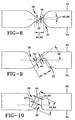
- the tear seam 12 has a transverse layer 38 separating the front 26 and back 32 grooves.
- the transverse layer 38 traverses from the closed bottom of one of the grooves to the closed bottom of the other groove.
- the transverse layer 38 has a length that is measured from the closed bottom of one of the grooves to the closed bottom of the other groove, as shown at reference character 40.
- the transverse layer 38 has a thickness 42 which varies along the length 40 of the transverse layer 38.
- the transverse layer 38 of the tear seam 12 tears upon the deployment of the airbag 16 at a point along the length of the transverse layer where the thickness 42 is at minimum.
- the transverse layer 38 of the tear seam 12 in the airbag cover forms an angle 46 with respect to the flat plane 18.
- the angle 46 is less than or equal to 90° and greater than or equal to 0°. In the preferred embodiment the angle 46 is equal to 72°.
- the depths of the front 26 and back 32 grooves of the tear seam 12 vary at different locations along the tear seam. This variation correspondingly slightly varies the length 40 of the transverse layer 38.
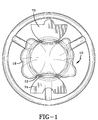
- the airbag cover 10 may have a non-rectangular configuration, such as an essentially circular configuration as is illustrated.
- the related art only discloses rectangular or square airbag covers.
- the airbag cover 10 has first and second hinges 48, 50.
- the first and second hinges are situated diametrically opposite from each other along the perimeter of the circular airbag cover 10. Thus, the first and second hinges are separated by an angle 52 of 180° as shown in FIGS. 6, 7 and 11.
- the tear seam 12 preferably comprises a first tear seam segment 54 within the circular airbag cover 10.
- This first tear seam segment 54 extends across the diameter of the circular airbag cover such that it is parallel to the first and second hinges 48, 50.
- the first tear seam segment forms an angle 56 with respect to the first and second hinges.
- the angle 56 is equal to 0°.
- the tear seam 12 also comprises a second tear seam segment 58 along one half of the perimeter of the circular airbag cover between the first and second hinges 48, 50.
- the second tear seam segment is bisected by the first tear seam segment 54.
- the second tear seam segment thereby comprises an upper 60 second tear seam segment half and a lower 62 second tear seam segment half.
- the tear seam 12 further comprises a third tear seam segment 64 along the remaining one half the perimeter circular airbag cover.
- the third tear seam segment 64 extends between the first and second hinges 48, 50.
- the third tear seam segment 64 is situated opposite the second tear seam segment 58 along the perimeter of the circular airbag cover 10.
- the third tear seam segment is bisected by the first tear seam segment 54 thereby comprising an upper 66 third tear seam segment half and a lower 68 third tear seam segment half.
- first tear seam segment 54, upper second tear seam segment half 60 and upper third tear seam segment half 66 form a first deployment door 70 in the circular airbag cover 10.
- the first deployment door pivots open on said first hinge 48 upon the deployment of the airbag 16 and the tearing of first tear seam segment 54, upper second tear seam segment half 60 and upper third tear seam segment half 66.
- the first deployment door 70 forms an angle 72 with respect to the substantially flat plane 18.
- the angle 72 is less than or equal to 270°.
- the first tear seam segment 54, lower second tear seam segment half 62 and lower third tear seam segment half 68 form a second deployment door 74 in the circular airbag cover 10.
- the second deployment door pivots open on the second hinge 50 upon the deployment of the airbag 16 and the tearing of the first tear seam segment, lower second tear seam segment half 62 and lower third tear seam segment half 68.
- the second deployment door 74 forms an angle 76 with respect flat plane 18. The angle 76 is less than or equal to 270°.
- the minimum thickness 44 of the transverse layer 38 along the length 40 of the transverse layer has different values at different locations along the tear seam 12.
- the minimum thickness 44 has its minimum value 78 along the first tear seam segment 54 and near a point 79 where the first tear seam segment bisects the second 58 and third 64 tear seams.
- the minimum thickness 44 of the transverse layer 38 along the length 40 of the transverse layer has different values at different locations along the tear seam 12.
- the minimum thickness 44 has its maximum value 80 at the point 81 on the upper second 60 and upper third 66 tear seam halves near the first hinge 48 and at the point 81 on the lower second 62 and lower third 68 tear seam halves near the second hinge 50.
- the minimum thickness 44 of the transverse layer 38 along the length 40 of the transverse layer 38 gradually transitions between thicknesses 78 and 80 along the upper second 60, upper third 66, lower second 62 and lower third 68 tear seam halves.
- a transitioning transverse layer is shown in FIG. 9, which is a cross sectional view of the transverse layer along lines 9-9 of FIGS. 6 and 7.
- the length 40 of the transverse layer 38 is preferably a minimum 82 along the first tear seam segment 54 and near the locations 79 wherein the first tear seam segment 54 bisects the second 58 and third 64 tear seams.
- the length 40 of the transverse layer 38 is at a maximum length 84 near the locations 81 on the upper second 60 and upper third 66 tear seam halves near the first hinge 48 as well as the locations 81 on the lower second 62 and lower third 68 tear seams halves near the second hinge 50.
- the length 40 of the transverse layer 38 of the tear seam 12 gradually transitions between lengths 84 and 82 along the upper second 60, upper third 66, lower second 62 and lower third 68 tear seam halves.
- the varying lengths and thicknesses of the transverse layer 38 of the tear seam 12 enable controlled operation of the airbag cover 10.
- the minimum thickness 78 which is preferably located along the first tear seam segment provides that the first tear seam segment will tear first upon deployment of the airbag 16.
- the thickness of the transverse layer 38 of the tear seam 12 increases as one moves from that point along the perimeter of the airbag cover towards the first and second hinges 48, 50. This feature helps control the rate at which the first 70 and second 74 deployment doors pivot open upon deployment of the airbag 16.
- the decreased length 40 of the transverse layer 38 at the first tear seam segment 54 provides sufficient strength and rigidity of the tear seam 12 such that the airbag cover 10 will not fail due to fatigue failure at the first tear seam segment 54 when the center of the airbag cover 10 is depressed, for example when the operator of the motor vehicle operates the horn.
- the angle 46 of the transverse layer 38 relative to the substantially flat plane 18 has preferred values at particular locations along the tear seam 12 in order to obtain the desired strength and rigidity and to prevent fatigue failure of the transverse layer of the tear seam.
- angle 46 is at a minimum 86 along the first tear seam segment 54 and near the locations 79 wherein the first tear seam segment bisects the second 58 and third 64 tear seams.
- the angle 46 has a maximum value 88 near the locations 81 on the upper second 60 and upper third 66 tear seam halves near the first hinge and near the locations on the lower second 62 and lower third 68 tear seam halves near the second hinge 50.
- the angle 46 of the transverse layer 38 of the tear seam 12 gradually transitions between angles 88 and 86 along the upper second 60, upper third 66, lower second 62, and lower third 68 tear seam halves.
- the angle 86 is zero degrees and the angle 88 is seventy-two degrees.
- the ratio of the maximum thickness 78 to the minimum thickness 80 is less than or equal to 2.
- the minimum thickness has a value of about .5 mm and the maximum thickness has a value of about .75 mm.
- the hinges 48, 50 may be formed within the airbag cover 10 by molding the back side 24 of the airbag cover 10 corresponding to the locations of the first and second hinges.
- the hinges pivot on generally linear hinge lines.
- the lengths of the hinge lines, as indicated at 90 and 92, may be between about 1.25cm and about 7.5 cm but is preferably about 3.1 cm.
- the airbag cover 10 also has reinforcing means 94.
- the reinforcing means 94 is connected to the hinges 48, 50 and prevents the deployment doors 70, 74 from completing detaching from the airbag cover 10 upon the tearing the tear seam 12, opening of the deployment doors and deployment of the airbag 16.
- the reinforcing means as well as the airbag cover, hinges, deployment doors and tear seam are all cast or molded out of an elastic polymer having somewhat rigid properties.
- the preferred material is a polymer available from Dupont and designated by their product code "DYM-350.”
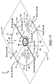
- the present invention contemplates a tear seam 12 configured within the airbag cover 10 such that an emblem 96 can be mounted anywhere on the front side 22 of the airbag cover 10 and remain safely attached to the airbag cover 10 during and throughout the deployment of the airbag 16.
- the emblem can be mounted by any fastening method chosen with sound engineering judgment.
- the tear seam and a portion of the emblem are adjacent to each other.
- the tear seam essentially follows a portion of the perimeter of the emblem.
- Such design encourages the emblem to remain affixed to the airbag cover during deployment of the airbag.
- the tear seam tears around the emblem without affecting the emblem's fixation to the airbag cover.
- the emblem 96 represented in FIGS. 6 and 7 is illustrated as circular and mounted in the center of the airbag cover. However, the present invention contemplates mounting an emblem of any shape onto any location of any shaped airbag cover.
Landscapes
- Engineering & Computer Science (AREA)
- Mechanical Engineering (AREA)
- Air Bags (AREA)
Applications Claiming Priority (2)
| Application Number | Priority Date | Filing Date | Title |
|---|---|---|---|
| US152436 | 1998-09-14 | ||
| US09/152,436 US6168189B1 (en) | 1998-09-14 | 1998-09-14 | Airbag cover |
Publications (3)
| Publication Number | Publication Date |
|---|---|
| EP0987149A2 true EP0987149A2 (fr) | 2000-03-22 |
| EP0987149A3 EP0987149A3 (fr) | 2000-09-27 |
| EP0987149B1 EP0987149B1 (fr) | 2003-11-12 |
Family
ID=22542911
Family Applications (1)
| Application Number | Title | Priority Date | Filing Date |
|---|---|---|---|
| EP99113620A Expired - Lifetime EP0987149B1 (fr) | 1998-09-14 | 1999-07-16 | Couvercle pour coussin de sécurité |
Country Status (3)
| Country | Link |
|---|---|
| US (1) | US6168189B1 (fr) |
| EP (1) | EP0987149B1 (fr) |
| DE (1) | DE69912707T2 (fr) |
Cited By (2)
| Publication number | Priority date | Publication date | Assignee | Title |
|---|---|---|---|---|
| WO2001074629A1 (fr) * | 2000-03-31 | 2001-10-11 | Delphi Technologies, Inc. | Couvercle d'airbag a lignes de rupture cachees |
| CN109747535A (zh) * | 2018-12-20 | 2019-05-14 | 铜陵有色金属集团铜冠物流有限公司 | 一种基于大数据的视联网信息管理系统 |
Families Citing this family (10)
| Publication number | Priority date | Publication date | Assignee | Title |
|---|---|---|---|---|
| US6540252B2 (en) * | 2001-06-06 | 2003-04-01 | Trw Vehicle Safety Systems Inc. | Dual seam air bag module cover |
| US7004497B2 (en) * | 2003-01-07 | 2006-02-28 | General Motors Corporation | Styling flexible driver air bag module and method of making same |
| US6921105B2 (en) * | 2003-03-04 | 2005-07-26 | Delphi Technologies, Inc. | Integrally molded passenger airbag cover |
| US7025374B2 (en) * | 2003-07-03 | 2006-04-11 | Intertec Systems | Airbag cover and tear seam |
| US7748732B2 (en) * | 2006-11-07 | 2010-07-06 | Autoliv Asp, Inc. | Airbag cover tear seam |
| JP2010173505A (ja) * | 2009-01-30 | 2010-08-12 | Toyoda Gosei Co Ltd | 助手席用エアバッグ装置 |
| WO2015187945A1 (fr) * | 2014-06-05 | 2015-12-10 | Key Safety Systems, Inc. | Couvercle de coussin de sécurité gonflable conducteur à emblème |
| EP3988400B1 (fr) * | 2019-06-18 | 2025-11-26 | Autoliv Development AB | Dispositif de coussin gonflable de sécurité de siège conducteur |
| CN114222685B (zh) * | 2019-09-17 | 2023-11-07 | 奥托立夫开发公司 | 驾驶座用安全气囊装置 |
| CN115257619A (zh) * | 2022-08-29 | 2022-11-01 | 宁波均胜汽车安全系统有限公司 | 侧气帘安装结构 |
Family Cites Families (17)
| Publication number | Priority date | Publication date | Assignee | Title |
|---|---|---|---|---|
| JPH0726209Y2 (ja) * | 1988-12-29 | 1995-06-14 | トヨタ自動車株式会社 | エアバッグカバー |
| JPH0694266B2 (ja) * | 1989-02-20 | 1994-11-24 | タカタ株式会社 | エアバッグ収納用カバー |
| JPH03186449A (ja) * | 1989-12-14 | 1991-08-14 | Takata Kk | エアバッグ装置のカバー |
| JP2527074B2 (ja) * | 1990-05-24 | 1996-08-21 | タカタ株式会社 | エアバッグ収納用カバ― |
| ES2066909T3 (es) * | 1990-06-09 | 1995-03-16 | Petri Ag | Carcasa para dispositivos amortiguadores de proteccion con almohadilla inflable para automoviles. |
| JPH06107102A (ja) * | 1992-09-25 | 1994-04-19 | Toyoda Gosei Co Ltd | エアバッグ装置のパッド |
| GB2282352A (en) * | 1993-10-02 | 1995-04-05 | Ford Motor Co | Mounting air bags in vehicle steering wheels. |
| JP3185515B2 (ja) * | 1994-02-17 | 2001-07-11 | 豊田合成株式会社 | エアバッグ装置のパッド |
| US5480184A (en) * | 1994-03-23 | 1996-01-02 | Young; William A. | Inflatable occupant restraint device |
| US5641554A (en) * | 1994-04-18 | 1997-06-24 | Toyoda Gosei Co., Ltd. | Cover pad for air bag device |
| EP0749872B1 (fr) * | 1995-06-21 | 2003-04-23 | Toyoda Gosei Co., Ltd. | Couvercle pour sac gonflable et procédé de fabrication |
| US5533749A (en) * | 1995-09-07 | 1996-07-09 | Morton International, Inc. | Apparatus for improved detachment of the deployment door of an airbag assembly |
| US5725241A (en) * | 1996-04-23 | 1998-03-10 | General Motors Corporation | Air bag cover assembly |
| DE19732022B4 (de) * | 1996-07-29 | 2004-02-12 | Autoliv Development Ab | Gassackeinrichtung mit integriertem Hupenschalter |
| DE29615261U1 (de) * | 1996-09-02 | 1997-01-16 | Trw Occupant Restraint Systems Gmbh, 73551 Alfdorf | Abdeckung eines in ein Fahrzeuglenkrad integrierten Gassack-Moduls |
| JP3419240B2 (ja) * | 1997-03-21 | 2003-06-23 | 豊田合成株式会社 | エアバッグ用パッドとその製造方法 |
| US6082762A (en) | 1998-05-22 | 2000-07-04 | Larry J. Winget | Air bag cover having a decorative applique preform bonded thereto and method of making same |
-
1998
- 1998-09-14 US US09/152,436 patent/US6168189B1/en not_active Expired - Fee Related
-
1999
- 1999-07-16 DE DE69912707T patent/DE69912707T2/de not_active Expired - Fee Related
- 1999-07-16 EP EP99113620A patent/EP0987149B1/fr not_active Expired - Lifetime
Non-Patent Citations (1)
| Title |
|---|
| None |
Cited By (2)
| Publication number | Priority date | Publication date | Assignee | Title |
|---|---|---|---|---|
| WO2001074629A1 (fr) * | 2000-03-31 | 2001-10-11 | Delphi Technologies, Inc. | Couvercle d'airbag a lignes de rupture cachees |
| CN109747535A (zh) * | 2018-12-20 | 2019-05-14 | 铜陵有色金属集团铜冠物流有限公司 | 一种基于大数据的视联网信息管理系统 |
Also Published As
| Publication number | Publication date |
|---|---|
| DE69912707T2 (de) | 2004-09-23 |
| EP0987149A3 (fr) | 2000-09-27 |
| US6168189B1 (en) | 2001-01-02 |
| EP0987149B1 (fr) | 2003-11-12 |
| DE69912707D1 (de) | 2003-12-18 |
Similar Documents
| Publication | Publication Date | Title |
|---|---|---|
| US6402189B1 (en) | Airbag door and method for making same | |
| EP0987149A2 (fr) | Couvercle pour coussin de sécurité | |
| US6976701B2 (en) | Airbag door and method for making same | |
| US5810388A (en) | Instrument panel air bag door and method of making thereof | |
| US6012735A (en) | Trim panel having air bag door | |
| US5154444A (en) | Air bag retainer with cutting flaps | |
| US5779262A (en) | Car interior finish member with air bag cover | |
| US5772240A (en) | Air-bag arrangement | |
| EP0928259B1 (fr) | Ligne de rupture frontale d'un panneau de dissimulation d'air bag | |
| US6672611B2 (en) | Air bag deployment chute and panel assembly | |
| US20030080540A1 (en) | Seamless door system for an airbag | |
| EP2100781B1 (fr) | Dispositif d'airbag de véhicule et son procédé de fabrication | |
| WO1998005536A1 (fr) | Panneau de garnissage dote d'une trappe a coussin gonflable de securite | |
| US6505850B2 (en) | Airbag covering cap comprising a support layer and a cover layer of different elasticities | |
| DE19640434A1 (de) | Einsatztüranordnung | |
| JP3321064B2 (ja) | ガス袋モジュール用のカバー | |
| US7093850B2 (en) | Instrument panel with integral hidden door cover and method of manufacture thereof | |
| US6045153A (en) | Instrument panel cover arrangement and method of making | |
| CA2060648A1 (fr) | Enveloppe modulaire pour assemblage de protection pneumatique | |
| US5449196A (en) | Pad for air bag | |
| US7025374B2 (en) | Airbag cover and tear seam | |
| EP1495921B1 (fr) | Couvercle de sac gonflable | |
| JP3039857U (ja) | エアバッグ展開用開口のための閉鎖要素 | |
| US6733032B2 (en) | Air bag cover assembly | |
| US20070246918A1 (en) | Instrument panel with integral hidden door cover and method of manufacture thereof |
Legal Events
| Date | Code | Title | Description |
|---|---|---|---|
| PUAI | Public reference made under article 153(3) epc to a published international application that has entered the european phase |
Free format text: ORIGINAL CODE: 0009012 |
|
| AK | Designated contracting states |
Kind code of ref document: A2 Designated state(s): DE ES FR GB IT |
|
| AX | Request for extension of the european patent |
Free format text: AL;LT;LV;MK;RO;SI |
|
| RAP1 | Party data changed (applicant data changed or rights of an application transferred) |
Owner name: BREED AUTOMOTIVE TECHNOLOGY, INC. |
|
| 17P | Request for examination filed |
Effective date: 20000522 |
|
| PUAL | Search report despatched |
Free format text: ORIGINAL CODE: 0009013 |
|
| AK | Designated contracting states |
Kind code of ref document: A3 Designated state(s): AT BE CH CY DE DK ES FI FR GB GR IE IT LI LU MC NL PT SE |
|
| AX | Request for extension of the european patent |
Free format text: AL;LT;LV;MK;RO;SI |
|
| AKX | Designation fees paid |
Free format text: DE ES FR GB IT |
|
| 17Q | First examination report despatched |
Effective date: 20020919 |
|
| GRAH | Despatch of communication of intention to grant a patent |
Free format text: ORIGINAL CODE: EPIDOS IGRA |
|
| GRAS | Grant fee paid |
Free format text: ORIGINAL CODE: EPIDOSNIGR3 |
|
| GRAA | (expected) grant |
Free format text: ORIGINAL CODE: 0009210 |
|
| AK | Designated contracting states |
Kind code of ref document: B1 Designated state(s): DE ES FR GB IT |
|
| REG | Reference to a national code |
Ref country code: GB Ref legal event code: FG4D |
|
| REF | Corresponds to: |
Ref document number: 69912707 Country of ref document: DE Date of ref document: 20031218 Kind code of ref document: P |
|
| PG25 | Lapsed in a contracting state [announced via postgrant information from national office to epo] |
Ref country code: ES Free format text: LAPSE BECAUSE OF FAILURE TO SUBMIT A TRANSLATION OF THE DESCRIPTION OR TO PAY THE FEE WITHIN THE PRESCRIBED TIME-LIMIT Effective date: 20040223 |
|
| ET | Fr: translation filed | ||
| PG25 | Lapsed in a contracting state [announced via postgrant information from national office to epo] |
Ref country code: GB Free format text: LAPSE BECAUSE OF NON-PAYMENT OF DUE FEES Effective date: 20040716 |
|
| PLBE | No opposition filed within time limit |
Free format text: ORIGINAL CODE: 0009261 |
|
| STAA | Information on the status of an ep patent application or granted ep patent |
Free format text: STATUS: NO OPPOSITION FILED WITHIN TIME LIMIT |
|
| 26N | No opposition filed |
Effective date: 20040813 |
|
| GBPC | Gb: european patent ceased through non-payment of renewal fee |
Effective date: 20040716 |
|
| REG | Reference to a national code |
Ref country code: FR Ref legal event code: TP |
|
| PGFP | Annual fee paid to national office [announced via postgrant information from national office to epo] |
Ref country code: DE Payment date: 20070731 Year of fee payment: 9 |
|
| PGFP | Annual fee paid to national office [announced via postgrant information from national office to epo] |
Ref country code: IT Payment date: 20070714 Year of fee payment: 9 |
|
| PGFP | Annual fee paid to national office [announced via postgrant information from national office to epo] |
Ref country code: FR Payment date: 20070706 Year of fee payment: 9 |
|
| PG25 | Lapsed in a contracting state [announced via postgrant information from national office to epo] |
Ref country code: DE Free format text: LAPSE BECAUSE OF NON-PAYMENT OF DUE FEES Effective date: 20090203 |
|
| REG | Reference to a national code |
Ref country code: FR Ref legal event code: ST Effective date: 20090331 |
|
| PG25 | Lapsed in a contracting state [announced via postgrant information from national office to epo] |
Ref country code: IT Free format text: LAPSE BECAUSE OF NON-PAYMENT OF DUE FEES Effective date: 20080716 Ref country code: FR Free format text: LAPSE BECAUSE OF NON-PAYMENT OF DUE FEES Effective date: 20080731 |