EP0987708B1 - Kassette - Google Patents
Kassette Download PDFInfo
- Publication number
- EP0987708B1 EP0987708B1 EP99117780A EP99117780A EP0987708B1 EP 0987708 B1 EP0987708 B1 EP 0987708B1 EP 99117780 A EP99117780 A EP 99117780A EP 99117780 A EP99117780 A EP 99117780A EP 0987708 B1 EP0987708 B1 EP 0987708B1
- Authority
- EP
- European Patent Office
- Prior art keywords
- cartridge
- mis
- insertion protection
- auto
- loading
- Prior art date
- Legal status (The legal status is an assumption and is not a legal conclusion. Google has not performed a legal analysis and makes no representation as to the accuracy of the status listed.)
- Expired - Lifetime
Links
Images









Classifications
-
- G—PHYSICS
- G11—INFORMATION STORAGE
- G11B—INFORMATION STORAGE BASED ON RELATIVE MOVEMENT BETWEEN RECORD CARRIER AND TRANSDUCER
- G11B23/00—Record carriers not specific to the method of recording or reproducing; Accessories, e.g. containers, specially adapted for co-operation with the recording or reproducing apparatus ; Intermediate mediums; Apparatus or processes specially adapted for their manufacture
- G11B23/02—Containers; Storing means both adapted to cooperate with the recording or reproducing means
- G11B23/03—Containers for flat record carriers
-
- G—PHYSICS
- G11—INFORMATION STORAGE
- G11B—INFORMATION STORAGE BASED ON RELATIVE MOVEMENT BETWEEN RECORD CARRIER AND TRANSDUCER
- G11B17/00—Guiding record carriers not specifically of filamentary or web form, or of supports therefor
- G11B17/02—Details
- G11B17/04—Feeding or guiding single record carrier to or from transducer unit
- G11B17/041—Feeding or guiding single record carrier to or from transducer unit specially adapted for discs contained within cartridges
- G11B17/043—Direct insertion, i.e. without external loading means
-
- G—PHYSICS
- G11—INFORMATION STORAGE
- G11B—INFORMATION STORAGE BASED ON RELATIVE MOVEMENT BETWEEN RECORD CARRIER AND TRANSDUCER
- G11B23/00—Record carriers not specific to the method of recording or reproducing; Accessories, e.g. containers, specially adapted for co-operation with the recording or reproducing apparatus ; Intermediate mediums; Apparatus or processes specially adapted for their manufacture
- G11B23/02—Containers; Storing means both adapted to cooperate with the recording or reproducing means
- G11B23/03—Containers for flat record carriers
- G11B23/0301—Details
- G11B23/0311—Wrong insertion preventing means
Definitions
- the present invention relates to a mis-insertion protection mechanism in a magnetic or optical disk cartridge for preventing the cartridge from being inserted into a disk drive in a wrong direction.
- the present invention concerns such a cartridge as defined in the preamble of claim 1.
- a cartridge is known from the document US-A-5 577 014.
- a magnetic or optical disk cartridge is generally in a rectangular shape and has a window opened for receiving an optical pickup and a shutter for opening/closing the window.
- a single-sided cartridge can be inserted into a disk drive only in one direction.
- a double-sided cartridge can be inserted into a disk drive in either one of two directions (i.e., it can be inserted with either one of the front side and the reverse side facing up).
- a mis-insertion protection mechanism in the cartridge hits a stopper provided in the disk drive so that the cartridge cannot be inserted any further.
- a conventional single-sided cartridge has a mis-insertion protection mechanism provided by differently shaping one of the four corners from the other corners.
- a 3.5" floppy disk cartridge 101 includes a corner 102 on the front edge thereof, which is chamfered.
- the other three corners 103, 104 and 105 of the cartridge 101 are rounded for easy insertion and easy handling of the cartridge 101, as well as for an aesthetic design.
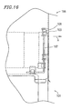
- Figure 13 illustrates an exemplary cartridge holder 106 for use in a disk drive receiving the cartridge 101 .
- the cartridge holder 106 is provided with a mis-insertion protection pin 107 made of a torsion spring.
- One end of the mis-insertion protection pin 107 is bent at about 90°, thereby forming a stopper 108 , and the other end 107A is secured on an outer surface of the cartridge holder 106 .
- the stopper 108 extends through a guide hole 109 of the cartridge holder 106 to be within the insertion path of the cartridge 101 (i.e., a path along which the cartridge 101 is inserted).
- the stopper 108 abuts a tab portion 110 of the cartridge holder 106 and is urged away from a side 111 thereof by virtue of the bias of the torsion spring.
- the insertion of the cartridge 101 forces the stopper 108 out of the insertion path of the cartridge 101 by overcoming the bias of the torsion spring (in the direction indicated by arrow A in Figure 14 ), thereby resulting in a state as illustrated in Figure 15 .
- the cartridge 101 is allowed to be inserted further into the cartridge holder 106 .
- the mis-insertion protection function is similarly provided when the cartridge 101 is inserted from the corner 104 (or 105 ) ( Figure 12 ).
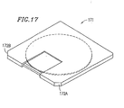
- Japanese Laid-Open Publication No. 57-113466 describes an exemplary mis-insertion protection mechanism for a double-sided cartridge as illustrated in Figure 17 .
- Both of the insertion-side corners 172A and 172B are chamfered, so that the cartridge exhibits the same profile whether it is faced up or faced down.
- the cartridge can be inserted into the cartridge holder whether it is faced up or faced down.
- optical disk there are one-sided optical disks (having a recording surface only on one side) and double-sided optical disks (having a recording surface on both sides). Recently, there is a need in the art to accommodate a single-sided disk in a single-sided cartridge and a double-sided disk in a double-sided cartridge, respectively, so that they can be used in the same disk drive. Along with the increase in the recording density of an optical disk, there is also a demand in the art for a cartridge accommodating a small-diameter optical-disk.
- an optical disk cartridge Since a pickup for optical disks is larger than a magnetic recording pickup, an optical disk cartridge has a larger window and also requires a larger area for the motion of the shutter ("shutter motion area"). Therefore, in a cartridge accommodating a small-diameter optical disk, the shutter motion area comes close to the side edges, and thus the corners, of the cartridge.
- the present invention concerns a cartridge as defined in the appended claims.
- the invention also concerns a system as further defined in the claims.
- the invention described herein makes possible the advantage of providing a mis-insertion protection mechanism in a magnetic or optical disk cartridge for reliably preventing mis-insertion of the cartridge, which can suitably be used in a cartridge with a large shutter motion area, and which can be used either in a single-sided cartridge or in a double-sided cartridge.
- Figure 1 is a schematic diagram illustrating a double-sided cartridge 1 according to Example 1 of the present invention.
- Figure 2 is a schematic diagram illustrating a cartridge holder 10 provided in an optical disk apparatus which receives the double-sided cartridge 1 .
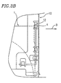
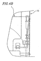
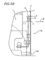
- Figures 3A , 3B , 4A , 4B , 5A and 5B are diagrams illustrating how the double-sided cartridge 1 is inserted into the cartridge holder 10 .
- the double-sided cartridge 1 accommodating an optical disk therein has a window 2 on both sides thereof for receiving a pickup of the disk drive, and a U-shaped slidable shutter 3 for opening/closing the window.
- the shutter 3 is movable toward either side of the window 2 , and is biased by a shutter spring (not shown) to close the window 2 .
- a shutter spring not shown
- the shutter 3 hits a shutter opener (not shown) provided in the disk drive, which then moves the shutter 3 to open the window 2 .
- the same shutter opener can move the shutter 3 to open the window 2 also when the cartridge 1 is inserted with its reverse side facing up, because the shutter 3 is movable toward either side of the window 2 .
- a mis-insertion protection slot 5 is provided along both side edges of the cartridge 1 near the rear edge (opposite to the shutter 3 ) thereof.
- the slot 5 comprises an inclined guide section 6 for guiding a mis-insertion protection pin 11 (further described later) and a stopper section 7 .
- the cartridge holder 10 is provided with the mis-insertion protection pin 11 made of a torsion spring.
- One end of the mis-insertion protection pin 11 is bent at about 90°, thereby forming a stopper 12 , and the other end 11A is secured on an outer surface of the cartridge holder 10 .
- the stopper 12 extends through a guide hole 13 of the cartridge holder 10 to be present within the insertion path of the cartridge 1 .
- the stopper 12 abuts a tab portion 14 of the cartridge holder 10 and is urged away from a side thereof by virtue of the bias of the torsion spring. In this state, the stopper 12 is designed to meet the rounded portion of the corner 4 of the cartridge 1 .
- the cartridge 1 Since the cartridge 1 is a double-sided cartridge, it exhibits the same profile whether it is faced up or faced down. Therefore, the cartridge 1 can of course be inserted into the cartridge holder 10 as illustrated in Figures 3A , 3B , 4A and 4B with the reverse side thereof facing up.
- the stopper 12 is urged into the slot 5 by virtue of the bias of the torsion spring and guided along the inclined guide section 6 of the slot 5 so as to hit the stopper section 7, as illustrated in Figures 5A and 5B . Since the stopper section 7 is generally perpendicular to a side surface 10A of the cartridge 1 , there is no force to move the stopper 12 in the direction indicated by arrow B .
- the cartridge 1 cannot be inserted further into the cartridge holder 10 , thereby providing the mis-insertion protection function. Still, the cartridge 1 can be pulled out from the cartridge holder 10 as the stopper 12 is guided along the guide section 6 out of the slot 5 .
- the mis-insertion protection function is similarly provided when the cartridge 1 is inserted into the cartridge holder 10 from the rear edge thereof with the reverse side facing up. In this way, the mis-insertion protection mechanism can be provided separately from the corner 4 and outside the motion area of the shutter 3 . Thus, desirable freedom is provided in designing the shutter 3 , thereby allowing the shutter 3 motion area to be as large as that in Example 1 (see Figure 1 ).
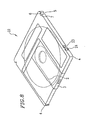
- Figure 6 is a schematic diagram illustrating a first single-sided cartridge 20 according to Example 2 of the present invention.
- Figure 7 is a diagram illustrating a mis-insertion of the first single-sided cartridge 20 .
- like reference numerals to those in the previously discussed figures denote like elements, will not further be described below.
- the first single-sided cartridge 20 is generally the same as the double-sided cartridge 1 according to Example 1 except for the following points.
- the shutter 3 is movable toward only one side of the window 2 because the cartridge 20 is a single-sided cartridge.
- a second slot 21 having a similar shape to that of the mis-insertion protection slot 5 , is provided along one side edge of the cartridge 20 near the front edge thereof.
- the side on which the second slot 21 is provided is opposite to the side toward which the shutter is moved to open the window 2 .
- the second slot 21 is different from the slot 5 in that the second slot 21 does not extend through the thickness of the cartridge 20 .
- the distance S1 between the second slot 21 and the front edge of the cartridge 20 is generally the same as the distance S2 between the slot 5 and the rear edge of the cartridge 20 .
- a mis-insertion protection function will be described, which is provided when the single-sided cartridge 20 is inserted into the cartridge holder 10 from the front edge, but with the reverse (wrong) side thereof facing up.
- the cartridge 20 is inserted to a certain depth into the cartridge holder 10 as illustrated in Figures 3A and 3B .
- the stopper 12 is urged into the second slot 21 by virtue of the bias of the torsion spring and guided along the inclined guide section 6 of the second slot 21 so as to hit the stopper section 7 , as illustrated in Figure 7 . Since the stopper section 7 is generally perpendicular to a side surface 20A of the cartridge 20 , there is no force to move the stopper 12 in the direction indicated by arrow B .
- the cartridge 20 cannot be inserted any further, thereby providing the mis-insertion protection function.
- the single-sided cartridge 20 is inserted into the cartridge holder 10 as described above with respect to the double-sided cartridge 1 in Example 1.
- the single-sided cartridge 20 is prevented from being inserted into the cartridge holder 10 with the reverse side thereof facing up.
- the slots 5 and 21 are located at generally the same distance ( S1 and S2 ) respectively from the front edge and the rear edge of the cartridge 20 , thereby stopping the mis-inserted cartridge 20 at generally the same depth in the cartridge holder 10 .
- a user can easily recognize the mis-insertion.
- the slots 5 and 21 can be provided separately from the corner 4 and outside the motion area of the shutter 3 , thereby facilitating the cartridge design.
- the second slot 21 does not extend to the front or upper surface of the cartridge 20 , so that the single-sided cartridge 20 , as viewed from the front side, exhibits the same profile as that of a double-sided cartridge, thereby adding an aesthetic advantage to the cartridge 20 .
- the second slot 21 may of course extend through the thickness of the cartridge 20 .
- the corners may have any other shape as long as the mis-insertion protection pin in the disk drive can be appropriately guided around the corners.
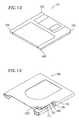
- Figure 8 is a schematic diagram illustrating a second single-sided cartridge 22 according to Example 3 of the present invention.
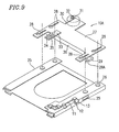
- Figure 9 is a schematic diagram illustrating a cartridge holder 10A of an optical disk apparatus which receives the second single-sided cartridge 22 .
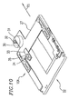
- Figures 10 and 11 are diagrams illustrating how the second single-sided cartridge 22 is inserted into the cartridge holder 10A .
- like reference numerals to those in the previously discussed figures denote like elements, will not further be described below.
- the second single-sided cartridge 22 is generally the same as the first single-sided cartridge 20 according to Example 2 except for the following points.
- the single-sided cartridge 22 has a concave auto-loading slot 24 provided along both side edges of the cartridge 22 near the front edge thereof, with a second slot 23 being provided on the rear side of the auto-loading slot 24 (The second slot 23 is generally the same in shape as the second slot 21 of Example 2).
- the auto-loading slot 24 engages with an auto-loading mechanism (further described later) provided in the optical disk apparatus to automatically load the cartridge 22 into the apparatus.
- the cartridge holder 10A includes a window 25 on both side surfaces thereof and a plurality of pins 26 provided integrally on the upper surface.
- the cartridge holder 10A further includes a movable plate 27 , which is provided with a plurality of elongated guide grooves 28 respectively engaging with the pins 26 .
- the movable plate 27 also includes a bent portion 36 .
- a plate spring 29 having an engagement protrusion 29A at the tip thereof, is provided at both ends of the bent portion 36 .
- a rack 30 is provided on the rear side of the movable plate 27 .
- the rack 30 meshes with a pinion gear 32 fit around a shaft of a motor 31 which is fixed in the apparatus.
- the movable plate 27 further includes a detection section 33 .
- a first sensor 34 and a second sensor 35 are fixed on the detection section 33 .
- Such a light emitting-receiving device can emit light downwardly so as to detect if the cartridge 22 is present under the light emitting-receiving device by detecting light reflected by the cartridge 22 .
- the corner 4 of the cartridge 22 hits the stopper 12 , as described above in Example 1, thereby moving the stopper 12 out of the insertion path of the cartridge 22 .
- the cartridge 22 is inserted further into the cartridge holder 10A while one side surface abuts the stopper 12 . Since the auto-loading slot 24 is in a concave shape which does not extend to the upper surface of the cartridge 22 , the stopper 12 passes over, and is not urged into, the auto-loading slot 24 .
- the presence of the cartridge 22 is detected by the first sensor 34 and then by the second sensor 35 of the detection section 33 . Meanwhile, the engagement protrusion 29A of the plate spring 29 is pushed by the corner 4 of the cartridge 22 out of the insertion path of the cartridge 22 through the window 25 , and then slides against the side surface of the cartridge 22 . As the cartridge 22 is inserted further into the cartridge holder 10A , the engagement protrusion 29A engages into the auto-loading slot 24 of the cartridge 22 by virtue of the resilient force of the plate spring 29 , thereby holding the cartridge 22.
- Figure 10 illustrates the cartridge 22 upon completion of the manual loading of the cartridge 22 into the cartridge holder 10A .
- the first sensor 34 and the second sensor 35 of the detection section 33 successively detect the cartridge 22 with a predetermined time lag therebetween.
- the motor 31 is activated and starts rotating the pinion gear 32 .
- the rotary force is transferred to the rack 30 , thereby moving the movable plate 27 rearwardly (in the direction indicated by arrow R1 ) along with the cartridge 22 being held by the movable plate 27 .
- FIG. 11 illustrates the cartridge 22 upon completion of the auto-loading operation.
- the second single-sided cartridge 22 has the auto-loading slot 24 shaped in a concave shape, so that the cartridge 22 provided with the mis-insertion protection slot 23 along the side surface thereof can be automatically loaded.
- a mis-insertion protection mechanism as described above is provided along one or both of the side edges of the cartridge, thereby successfully providing a reliable mis-insertion protection function to a disk cartridge, in which it is difficult to differentiate the respective shapes of the corners from one another.
Landscapes
- Feeding And Guiding Record Carriers (AREA)
- Packaging For Recording Disks (AREA)
- Holding Or Fastening Of Disk On Rotational Shaft (AREA)
Claims (16)
- Kassette (1) für die Aufnahme einer Platte, wobei:wobei die Kassettenhalterung (10) ein Fehleinschub-Schutzelement (11, 12) besitzt, das in einem Einschubweg vorgesehen ist, längs dessen die Kassette in die Kassettenhalterung (10) eingeschoben wird;die Kassette (1) eine rechtwinklige Form mit ersten bis vierten Ecken (4) besitzt;wenigstens zwei Fehleinschub-Schutzmechanismen (5, 6, 7) jeweils an einer Position vorgesehen sind, die sich an einem Seitenflächenabschnitt der Kassette (1) befindet, wobei die wenigstens zwei Fehleinschub-Schutzmechanismen (5, 6, 7) dazu vorgesehen sind, ein Einschieben der Kassette (1) in eine Kassettenhalterung (10) in einer falschen Richtung zu verhindern;
jede der ersten bis vierten Ecken (4) so geformt ist, dass die Kassette in die Kassettenhalterung (10) eingeschoben werden kann;
der Seitenflächenabschnitt eine erste Seitenfläche und eine zweite Seitenfläche besitzt, wovon jede in einer Richtung ausgebildet ist, die zu einer Oberfläche der Platte im Wesentlichen senkrecht ist und zu einer Richtung, in der die Kassette (1) in die Kassettenhalterung (10) eingeschoben wird, im Wesentlichen parallel ist;
die wenigstens zwei Fehleinschub-Schutzmechanismen (5, 6, 7) einen ersten Fehleinschubmechanismus (5, 6, 7), der in der ersten Seitenfläche vorgesehen ist, und einen zweiten Fehleinschubmechanismus (5, 6, 7), der in der zweiten Seitenfläche vorgesehen ist, umfassen;
sowohl der erste als auch der zweite Fehleinschub-Schutzmechanismus (5, 6, 7) so geformt ist, dass er mit dem Fehleinschub-Schutzelement (11, 12) in Eingriff gelangt;
sowohl der erste als auch der zweite Fehleinschub-Schutzmechanismus (5, 6, 7) in der Nähe der Hinterkante der Kassette gegenüber dem Verschluss (3) vorgesehen ist;
die wenigstens zwei Fehleinschub-Schutzmechanismen (5, 6, 7) jeweils an einer Position vorgesehen sind, die von jeder der ersten bis vierten Ecken (4) beabstandet ist;
jede der ersten bis vierten Ecken (4) so geformt ist, dass das Fehleinschub-Schutzelement anliegt, damit das Fehleinschub-Schutzelement (12) aus dem Einschubweg bewegt wird;
der erste Fehleinschub-Schutzmechanismus einen ersten Schlitz aufweist, der in der ersten Seitenfläche ausgebildet ist, und
der zweite Fehleinschub-Schutzmechanismus einen zweiten Schlitz aufweist, der in der zweiten Seitenfläche ausgebildet ist,
dadurch gekennzeichnet, dass
der erste Schlitz umfasst:einen ersten geneigten Führungsabschnitt (6), der eine in Bezug auf die erste Seitenfläche geneigte Fläche aufweist, um das Fehleinschub-Schutzelement (12) zu führen; undeinen ersten Anschlag (7), der im Wesentlichen senkrecht zu der ersten Seitenfläche angeordnet ist, um mit dem Fehleinschub-Schutzelement (12) in Kontakt zu gelangen, um ein falsches Einschieben der Kassette zu verhindern, und dass
der zweite Schlitz umfasst:einen zweiten geneigten Führungsabschnitt (6), der eine in Bezug auf die zweite Seitenfläche geneigte Fläche aufweist, um das Fehleinschub-Schutzelement zu führen; undeinen zweiten Anschlag (7), der im Wesentlichen senkrecht zu der zweiten Seitenfläche angeordnet ist, um mit dem Fehleinschub-Schutzelement in Kontakt zu gelangen, um ein falsches Einschieben der Kassette zu verhindern. - Kassette nach Anspruch 1, wobei die Kassette eine doppelseitige Kassette ist.
- Kassette nach Anspruch 1, bei der ferner ein dritter Fehleinschub-Schutzmechanismus (21) entweder in der ersten Seitenfläche oder in der zweiten Seitenfläche vorgesehen ist, um ein Einschieben der Kassette in die Kassettenhalterung in einer falschen Richtung zu verhindern.
- Kassette nach Anspruch 1, bei der:die erste Ecke an die erste Seitenfläche angrenzt und die zweite Ecke an die zweite Seitenfläche angrenzt; undeine Strecke zwischen dem ersten Fehleinschub-Schutzmechanismus und der ersten Ecke im Wesentlichen gleich einer Strecke zwischen dem zweiten Fehleinschub-Schutzmechanismus und der zweiten Ecke ist.
- Kassette nach Anspruch 4, bei der:die dritte Ecke an die erste Seitenfläche angrenzt und die vierte Ecke an die zweite Seitenfläche angrenzt; undeine Strecke (S2) zwischen dem ersten Fehleinschub-Schutzmechanismus und der ersten Ecke im Wesentlichen gleich einer Strecke (S1) zwischen dem dritten Fehleinschub-Schutzmechanismus (21) und der dritten oder der vierten Ecke ist.
- Kassette nach Anspruch 1, wobei die Kassette eine einseitige Kassette ist.
- Kassette nach Anspruch 1, wobei:die Kassette femer eine Öffnung (2) und einen Verschluss (3) zum Öffnen/Schließen der Öffnung aufweist; unddie wenigstens zwei Fehleinschub-Schutzmechanismen außerhalb eines Bewegungsbereichs des Verschlusses ausgebildet sind.
- Kassette nach Anspruch 7, bei der der Verschluss zu jeder Seite der Öffnung beweglich ist.
- Kassette nach Anspruch 7, bei der der Verschluss nur zu einer Seite der Öffnung beweglich ist.
- System, das in Kombination eine Selbstladevorrichtung und eine Kassette nach Anspruch 1 umfasst, wobei:die Selbstladevorrichtung umfasst:eine Kassettenhalterung (10) zum Halten der Kassette (1); undeinen Selbstlademechanismus zum Laden der Kassette; unddie Kassettenhalterung ein Fehleinschub-Schutzelement (11, 12) aufweist, das so geformt ist, dass es mit jedem der wenigstens zwei Fehleinschub-Schutzmechanismen (5, 6, 7) in Eingriff gelangt.
- System nach Anspruch 10, bei dem der Selbstlademechanismus femer einen Detektor zum Erfassen der Kassette umfasst.
- Kassette nach Anspruch 1, wobei:die Kassette ferner einen ersten konkaven Selbstladeschlitz (24) und einen zweiten konkaven Selbstladeschlitz (24) umfasst, die in dem Seitenflächenabschnitt vorgesehen sind;die wenigstens zwei Fehleinschub-Schutzmechanismen ferner einen dritten Fehleinschub-Schutzmechanismus (21, 23) umfassen, der in der ersten Seitenfläche vorgesehen ist;der erste Selbstladeschlitz (24) in der ersten Seitenfläche vorgesehen ist und der zweite Selbstladeschlitz (24) in der zweiten Seitenfläche vorgesehen ist;der erste Selbstladeschlitz (24) in Bezug auf den dritten Fehleinschub-Schutzmechanismus (21; 23) auf einer dem ersten Fehleinschub-Schutzmechanismus (5, 6 7) gegenüberliegenden Seite vorgesehen ist;der dritte Fehleinschub-Schutzmechanismus so geformt ist, dass er mit dem Fehleinschub-Schutzelement in Eingriff gelangt; undder erste Selbstladeschlitz (24) so angeordnet ist, dass das Fehleinschub-Schutzelement (11, 12) mit dem dritten Fehleinschub-Schutzmechanismus (21, 23) in Eingriff gelangt, nachdem sich das Fehleinschub-Schutzelement über den ersten Selbstladeschlitz bewegt hat.
- Kassette nach Anspruch 12, wobei die Kassette eine einseitige Kassette ist.
- System, das in Kombination eine Selbstladevorrichtung und eine Kassette nach Anspruch 12 umfasst, wobei:die Selbstladevorrichtung umfasst:eine Kassettenhalterung zum Halten der Kassette; undeinen Selbstlademechanismus zum Laden der Kassette;die Kassettenhalterung ein Fehleinschub-Schutzelement (11, 12) aufweist, das so geformt ist, dass es mit jedem der wenigstens drei Fehleinschub-Schutzmechanismen (5, 6, 7, 21, 23) in Eingriff gelangt; undder Selbstlademechanismus einen ersten Eingriffvorsprung und einen zweiten Eingriffvorsprung umfasst, um mit dem ersten bzw. mit dem zweiten Selbstladeschlitz (24) in Eingriff zu gelangen.
- System nach Anspruch 14, bei dem der Selbstlademechanismus ferner einen Detektor (33-35) zum Erfassen der Kassette umfasst.
- System nach Anspruch 15, bei dem:der Selbstlademechanismus ferner eine bewegliche Platte (27) aufweist, die mit dem ersten und mit dem zweiten Eingriffvorsprung gekoppelt ist; unddie bewegliche Platte ihre Bewegung längs der Kassette in Reaktion auf eine Erfassung der Kassette durch den Detektor beginnt.
Applications Claiming Priority (2)
| Application Number | Priority Date | Filing Date | Title |
|---|---|---|---|
| JP26113798 | 1998-09-16 | ||
| JP26113798 | 1998-09-16 |
Publications (3)
| Publication Number | Publication Date |
|---|---|
| EP0987708A2 EP0987708A2 (de) | 2000-03-22 |
| EP0987708A3 EP0987708A3 (de) | 2000-03-29 |
| EP0987708B1 true EP0987708B1 (de) | 2004-09-01 |
Family
ID=17357615
Family Applications (1)
| Application Number | Title | Priority Date | Filing Date |
|---|---|---|---|
| EP99117780A Expired - Lifetime EP0987708B1 (de) | 1998-09-16 | 1999-09-09 | Kassette |
Country Status (10)
| Country | Link |
|---|---|
| US (2) | US6272094B1 (de) |
| EP (1) | EP0987708B1 (de) |
| JP (1) | JP3085537B2 (de) |
| KR (1) | KR100371243B1 (de) |
| CN (1) | CN1211801C (de) |
| AU (1) | AU742791B2 (de) |
| BR (1) | BR9906955A (de) |
| CA (1) | CA2310051C (de) |
| DE (1) | DE69919798T2 (de) |
| WO (1) | WO2000016334A1 (de) |
Families Citing this family (4)
| Publication number | Priority date | Publication date | Assignee | Title |
|---|---|---|---|---|
| US6711119B1 (en) * | 1998-01-21 | 2004-03-23 | Hitachi, Ltd. | Disk cartridge with a holder having disk information on it |
| KR100371243B1 (ko) * | 1998-09-16 | 2003-02-07 | 마쯔시다덴기산교 가부시키가이샤 | 카트리지 |
| US6411596B1 (en) * | 1999-03-16 | 2002-06-25 | Canon Kabushiki Kaisha | Magneto-optical disk cartridge and magneto-optical disk apparatus |
| KR100727915B1 (ko) * | 2001-07-20 | 2007-06-13 | 삼성전자주식회사 | 디스크 카트리지 및 디스크 드라이브 장치 |
Family Cites Families (11)
| Publication number | Priority date | Publication date | Assignee | Title |
|---|---|---|---|---|
| JPS606938Y2 (ja) | 1980-08-14 | 1985-03-07 | ソニー株式会社 | 記録再生用デイスクカセツト |
| US5164935A (en) * | 1990-06-15 | 1992-11-17 | Mitsubishi Electric Company | Magneto-optical disk storage having erroneous insertion prevention mechanism |
| JPH07220348A (ja) | 1994-01-27 | 1995-08-18 | Nkk Corp | ディスクカートリッジ逆差し防止機構 |
| JPH07249279A (ja) * | 1994-03-10 | 1995-09-26 | Sony Corp | ディスクカートリッジ |
| JP2898886B2 (ja) * | 1994-09-20 | 1999-06-02 | 松下電器産業株式会社 | ディスクカートリッジ |
| US5991260A (en) * | 1995-02-20 | 1999-11-23 | Hitachi, Ltd. | Disk cartridge and disk device using the same |
| JPH09231713A (ja) * | 1995-12-20 | 1997-09-05 | Fuji Photo Film Co Ltd | 磁気ディスクカートリッジおよび磁気ディスク駆動装置 |
| JP3618500B2 (ja) * | 1997-01-22 | 2005-02-09 | 富士写真フイルム株式会社 | 磁気ディスクカートリッジ用アダプター |
| JPH1196719A (ja) | 1997-09-22 | 1999-04-09 | Teac Corp | ディスクカートリッジ及びディスク装置 |
| JPH11288572A (ja) | 1998-04-01 | 1999-10-19 | Tdk Corp | ディスクカートリッジ |
| KR100371243B1 (ko) * | 1998-09-16 | 2003-02-07 | 마쯔시다덴기산교 가부시키가이샤 | 카트리지 |
-
1999
- 1999-09-06 KR KR10-2000-7005339A patent/KR100371243B1/ko not_active Expired - Fee Related
- 1999-09-06 AU AU54500/99A patent/AU742791B2/en not_active Expired
- 1999-09-06 BR BR9906955-5A patent/BR9906955A/pt not_active Application Discontinuation
- 1999-09-06 CA CA002310051A patent/CA2310051C/en not_active Expired - Lifetime
- 1999-09-06 WO PCT/JP1999/004844 patent/WO2000016334A1/en not_active Ceased
- 1999-09-06 CN CNB998021385A patent/CN1211801C/zh not_active Expired - Fee Related
- 1999-09-09 DE DE69919798T patent/DE69919798T2/de not_active Expired - Lifetime
- 1999-09-09 EP EP99117780A patent/EP0987708B1/de not_active Expired - Lifetime
- 1999-09-13 US US09/395,008 patent/US6272094B1/en not_active Expired - Lifetime
-
2000
- 2000-02-01 JP JP2000024530A patent/JP3085537B2/ja not_active Expired - Lifetime
-
2001
- 2001-06-20 US US09/885,662 patent/US6353586B2/en not_active Expired - Lifetime
Also Published As
| Publication number | Publication date |
|---|---|
| CA2310051A1 (en) | 2000-03-23 |
| JP2000173222A (ja) | 2000-06-23 |
| DE69919798T2 (de) | 2005-09-22 |
| BR9906955A (pt) | 2000-10-03 |
| CA2310051C (en) | 2002-04-23 |
| KR20010032152A (ko) | 2001-04-16 |
| AU5450099A (en) | 2000-04-03 |
| CN1288570A (zh) | 2001-03-21 |
| JP3085537B2 (ja) | 2000-09-11 |
| AU742791B2 (en) | 2002-01-10 |
| EP0987708A3 (de) | 2000-03-29 |
| US6272094B1 (en) | 2001-08-07 |
| CN1211801C (zh) | 2005-07-20 |
| DE69919798D1 (de) | 2004-10-07 |
| US6353586B2 (en) | 2002-03-05 |
| US20010033540A1 (en) | 2001-10-25 |
| KR100371243B1 (ko) | 2003-02-07 |
| EP0987708A2 (de) | 2000-03-22 |
| WO2000016334A1 (en) | 2000-03-23 |
Similar Documents
| Publication | Publication Date | Title |
|---|---|---|
| US5040167A (en) | Disk cartridge | |
| EP0653756B1 (de) | Plattenkassette | |
| EP0402037B1 (de) | Plattenkassette | |
| EP0533463B1 (de) | Plattenkassette mit Falschaufzeichnungsschutzmechanismus | |
| US6075763A (en) | Disk cartridge and disk device using the same | |
| EP0205074A2 (de) | System zum Laden einer Plattenkassette in ein Plattenwiedergabegerät | |
| EP0987708B1 (de) | Kassette | |
| US7556195B2 (en) | Card reader and writer | |
| US5465246A (en) | Device insuring safe insertion of cartridges into loading apparatus of playback and/or recording units | |
| JP3085534B2 (ja) | カートリッジ | |
| TWI322413B (de) | ||
| JP2709034B2 (ja) | 光ディスク装置 | |
| US6392986B1 (en) | Optical disk cartridge | |
| EP0939404B1 (de) | Kassette und Aufbewahrungsbehälter für Kassette | |
| US7672077B2 (en) | Auto loading device for data storage cartridges | |
| JP3621698B2 (ja) | 光ディスクカートリッジ及び光ディスクカートリッジのシャッタ開閉装置 | |
| JPH06333365A (ja) | ディスクカートリッジ | |
| JPH07153155A (ja) | 記録媒体再生装置 | |
| JP2802269B2 (ja) | ディスク装置 | |
| JPH07111002A (ja) | ローディング機構 | |
| JPH11283353A (ja) | 磁気ディスクカートリッジ | |
| JPH07262737A (ja) | ディスク用カートリッジ | |
| JPH10199184A (ja) | ディスクカートリッジ | |
| JPH02143943A (ja) | 記録媒体内蔵マガジン操作装置 |
Legal Events
| Date | Code | Title | Description |
|---|---|---|---|
| PUAI | Public reference made under article 153(3) epc to a published international application that has entered the european phase |
Free format text: ORIGINAL CODE: 0009012 |
|
| PUAL | Search report despatched |
Free format text: ORIGINAL CODE: 0009013 |
|
| AK | Designated contracting states |
Kind code of ref document: A2 Designated state(s): AT BE CH CY DE DK ES FI FR GB GR IE IT LI LU MC NL PT SE |
|
| AX | Request for extension of the european patent |
Free format text: AL;LT;LV;MK;RO;SI |
|
| AK | Designated contracting states |
Kind code of ref document: A3 Designated state(s): AT BE CH CY DE DK ES FI FR GB GR IE IT LI LU MC NL PT SE |
|
| AX | Request for extension of the european patent |
Free format text: AL;LT;LV;MK;RO;SI |
|
| RIC1 | Information provided on ipc code assigned before grant |
Free format text: 7G 11B 23/03 A |
|
| 17P | Request for examination filed |
Effective date: 20000406 |
|
| 17Q | First examination report despatched |
Effective date: 20000915 |
|
| AKX | Designation fees paid |
Free format text: DE FR GB |
|
| GRAP | Despatch of communication of intention to grant a patent |
Free format text: ORIGINAL CODE: EPIDOSNIGR1 |
|
| GRAS | Grant fee paid |
Free format text: ORIGINAL CODE: EPIDOSNIGR3 |
|
| GRAA | (expected) grant |
Free format text: ORIGINAL CODE: 0009210 |
|
| AK | Designated contracting states |
Kind code of ref document: B1 Designated state(s): DE FR GB |
|
| REG | Reference to a national code |
Ref country code: GB Ref legal event code: FG4D |
|
| REF | Corresponds to: |
Ref document number: 69919798 Country of ref document: DE Date of ref document: 20041007 Kind code of ref document: P |
|
| ET | Fr: translation filed | ||
| PLBE | No opposition filed within time limit |
Free format text: ORIGINAL CODE: 0009261 |
|
| STAA | Information on the status of an ep patent application or granted ep patent |
Free format text: STATUS: NO OPPOSITION FILED WITHIN TIME LIMIT |
|
| 26N | No opposition filed |
Effective date: 20050602 |
|
| REG | Reference to a national code |
Ref country code: FR Ref legal event code: PLFP Year of fee payment: 18 |
|
| REG | Reference to a national code |
Ref country code: FR Ref legal event code: PLFP Year of fee payment: 19 |
|
| REG | Reference to a national code |
Ref country code: FR Ref legal event code: PLFP Year of fee payment: 20 |
|
| PGFP | Annual fee paid to national office [announced via postgrant information from national office to epo] |
Ref country code: DE Payment date: 20180828 Year of fee payment: 20 Ref country code: FR Payment date: 20180813 Year of fee payment: 20 |
|
| PGFP | Annual fee paid to national office [announced via postgrant information from national office to epo] |
Ref country code: GB Payment date: 20180905 Year of fee payment: 20 |
|
| REG | Reference to a national code |
Ref country code: DE Ref legal event code: R071 Ref document number: 69919798 Country of ref document: DE |
|
| REG | Reference to a national code |
Ref country code: GB Ref legal event code: PE20 Expiry date: 20190908 |
|
| PG25 | Lapsed in a contracting state [announced via postgrant information from national office to epo] |
Ref country code: GB Free format text: LAPSE BECAUSE OF EXPIRATION OF PROTECTION Effective date: 20190908 |