EP0988529B1 - Dispositifs microfluidiques a geometrie de canaux amelioree - Google Patents
Dispositifs microfluidiques a geometrie de canaux amelioree Download PDFInfo
- Publication number
- EP0988529B1 EP0988529B1 EP98918182.1A EP98918182A EP0988529B1 EP 0988529 B1 EP0988529 B1 EP 0988529B1 EP 98918182 A EP98918182 A EP 98918182A EP 0988529 B1 EP0988529 B1 EP 0988529B1
- Authority
- EP
- European Patent Office
- Prior art keywords
- sample
- channel
- intersection
- analysis
- reservoir
- Prior art date
- Legal status (The legal status is an assumption and is not a legal conclusion. Google has not performed a legal analysis and makes no representation as to the accuracy of the status listed.)
- Expired - Lifetime
Links
- 238000011068 loading method Methods 0.000 claims description 130
- 238000004458 analytical method Methods 0.000 claims description 128
- 239000002699 waste material Substances 0.000 claims description 77
- 239000000463 material Substances 0.000 claims description 49
- 238000000034 method Methods 0.000 claims description 19
- 239000000523 sample Substances 0.000 description 297
- 239000012530 fluid Substances 0.000 description 51
- 239000007924 injection Substances 0.000 description 39
- 238000002347 injection Methods 0.000 description 39
- 239000000758 substrate Substances 0.000 description 39
- 239000000872 buffer Substances 0.000 description 30
- 238000004891 communication Methods 0.000 description 26
- 238000000926 separation method Methods 0.000 description 24
- 238000005251 capillar electrophoresis Methods 0.000 description 21
- 230000036316 preload Effects 0.000 description 19
- 230000008901 benefit Effects 0.000 description 11
- 235000012431 wafers Nutrition 0.000 description 11
- VYPSYNLAJGMNEJ-UHFFFAOYSA-N Silicium dioxide Chemical compound O=[Si]=O VYPSYNLAJGMNEJ-UHFFFAOYSA-N 0.000 description 10
- 150000007523 nucleic acids Chemical group 0.000 description 10
- 230000000694 effects Effects 0.000 description 8
- 238000007873 sieving Methods 0.000 description 8
- 238000010348 incorporation Methods 0.000 description 6
- 102000039446 nucleic acids Human genes 0.000 description 6
- 108020004707 nucleic acids Proteins 0.000 description 6
- 238000001514 detection method Methods 0.000 description 5
- 239000000975 dye Substances 0.000 description 5
- 239000011521 glass Substances 0.000 description 5
- 238000004519 manufacturing process Methods 0.000 description 5
- 239000011159 matrix material Substances 0.000 description 5
- -1 polydimethylsiloxanes Polymers 0.000 description 5
- 241000894007 species Species 0.000 description 5
- 208000034454 F12-related hereditary angioedema with normal C1Inh Diseases 0.000 description 4
- 238000012864 cross contamination Methods 0.000 description 4
- 230000005684 electric field Effects 0.000 description 4
- 208000016861 hereditary angioedema type 3 Diseases 0.000 description 4
- 239000003550 marker Substances 0.000 description 4
- 229920000642 polymer Polymers 0.000 description 4
- 239000000377 silicon dioxide Substances 0.000 description 4
- XUIMIQQOPSSXEZ-UHFFFAOYSA-N Silicon Chemical compound [Si] XUIMIQQOPSSXEZ-UHFFFAOYSA-N 0.000 description 3
- 238000003556 assay Methods 0.000 description 3
- 239000003153 chemical reaction reagent Substances 0.000 description 3
- 238000010790 dilution Methods 0.000 description 3
- 239000012895 dilution Substances 0.000 description 3
- 238000005370 electroosmosis Methods 0.000 description 3
- 239000007850 fluorescent dye Substances 0.000 description 3
- 239000002609 medium Substances 0.000 description 3
- 230000005012 migration Effects 0.000 description 3
- 238000013508 migration Methods 0.000 description 3
- 102000004169 proteins and genes Human genes 0.000 description 3
- 239000010703 silicon Substances 0.000 description 3
- 229910052710 silicon Inorganic materials 0.000 description 3
- 239000007787 solid Substances 0.000 description 3
- 239000000126 substance Substances 0.000 description 3
- 238000009825 accumulation Methods 0.000 description 2
- XECAHXYUAAWDEL-UHFFFAOYSA-N acrylonitrile butadiene styrene Chemical compound C=CC=C.C=CC#N.C=CC1=CC=CC=C1 XECAHXYUAAWDEL-UHFFFAOYSA-N 0.000 description 2
- 239000004676 acrylonitrile butadiene styrene Substances 0.000 description 2
- 229920000122 acrylonitrile butadiene styrene Polymers 0.000 description 2
- 230000000740 bleeding effect Effects 0.000 description 2
- 239000000470 constituent Substances 0.000 description 2
- 238000009792 diffusion process Methods 0.000 description 2
- 235000013870 dimethyl polysiloxane Nutrition 0.000 description 2
- 238000001962 electrophoresis Methods 0.000 description 2
- 238000005516 engineering process Methods 0.000 description 2
- 238000011049 filling Methods 0.000 description 2
- 239000012634 fragment Substances 0.000 description 2
- 238000009830 intercalation Methods 0.000 description 2
- 230000037230 mobility Effects 0.000 description 2
- 239000003068 molecular probe Substances 0.000 description 2
- 229920000435 poly(dimethylsiloxane) Polymers 0.000 description 2
- 229920003229 poly(methyl methacrylate) Polymers 0.000 description 2
- 239000004926 polymethyl methacrylate Substances 0.000 description 2
- 230000008569 process Effects 0.000 description 2
- 108090000623 proteins and genes Proteins 0.000 description 2
- 230000009467 reduction Effects 0.000 description 2
- 239000012146 running buffer Substances 0.000 description 2
- 238000003631 wet chemical etching Methods 0.000 description 2
- JBRZTFJDHDCESZ-UHFFFAOYSA-N AsGa Chemical compound [As]#[Ga] JBRZTFJDHDCESZ-UHFFFAOYSA-N 0.000 description 1
- 230000002112 DNA intercalation Effects 0.000 description 1
- KRHYYFGTRYWZRS-UHFFFAOYSA-M Fluoride anion Chemical compound [F-] KRHYYFGTRYWZRS-UHFFFAOYSA-M 0.000 description 1
- 229910001218 Gallium arsenide Inorganic materials 0.000 description 1
- 241001354532 Holozonia filipes Species 0.000 description 1
- 108091005461 Nucleic proteins Proteins 0.000 description 1
- 239000004698 Polyethylene Substances 0.000 description 1
- 239000004743 Polypropylene Substances 0.000 description 1
- 239000004793 Polystyrene Substances 0.000 description 1
- 230000009471 action Effects 0.000 description 1
- 230000006978 adaptation Effects 0.000 description 1
- 238000012742 biochemical analysis Methods 0.000 description 1
- 230000015556 catabolic process Effects 0.000 description 1
- 239000002801 charged material Substances 0.000 description 1
- 238000006243 chemical reaction Methods 0.000 description 1
- 238000000576 coating method Methods 0.000 description 1
- 230000000295 complement effect Effects 0.000 description 1
- 239000005331 crown glasses (windows) Substances 0.000 description 1
- 238000006731 degradation reaction Methods 0.000 description 1
- 238000000151 deposition Methods 0.000 description 1
- 238000013461 design Methods 0.000 description 1
- 238000011161 development Methods 0.000 description 1
- 230000018109 developmental process Effects 0.000 description 1
- 239000013070 direct material Substances 0.000 description 1
- 238000006073 displacement reaction Methods 0.000 description 1
- 238000005553 drilling Methods 0.000 description 1
- 238000004049 embossing Methods 0.000 description 1
- 230000005284 excitation Effects 0.000 description 1
- 238000007667 floating Methods 0.000 description 1
- MHMNJMPURVTYEJ-UHFFFAOYSA-N fluorescein-5-isothiocyanate Chemical compound O1C(=O)C2=CC(N=C=S)=CC=C2C21C1=CC=C(O)C=C1OC1=CC(O)=CC=C21 MHMNJMPURVTYEJ-UHFFFAOYSA-N 0.000 description 1
- 238000001506 fluorescence spectroscopy Methods 0.000 description 1
- 239000000446 fuel Substances 0.000 description 1
- 239000005350 fused silica glass Substances 0.000 description 1
- 238000012252 genetic analysis Methods 0.000 description 1
- 229910052736 halogen Inorganic materials 0.000 description 1
- 150000002367 halogens Chemical class 0.000 description 1
- 230000012447 hatching Effects 0.000 description 1
- 238000001746 injection moulding Methods 0.000 description 1
- 230000014759 maintenance of location Effects 0.000 description 1
- 238000005459 micromachining Methods 0.000 description 1
- 238000003801 milling Methods 0.000 description 1
- 238000012986 modification Methods 0.000 description 1
- 230000004048 modification Effects 0.000 description 1
- 238000005457 optimization Methods 0.000 description 1
- 239000005022 packaging material Substances 0.000 description 1
- 238000000206 photolithography Methods 0.000 description 1
- 229920002492 poly(sulfone) Polymers 0.000 description 1
- 229920002401 polyacrylamide Polymers 0.000 description 1
- 229920000515 polycarbonate Polymers 0.000 description 1
- 239000004417 polycarbonate Substances 0.000 description 1
- 229910021420 polycrystalline silicon Inorganic materials 0.000 description 1
- 229920000573 polyethylene Polymers 0.000 description 1
- 229920000306 polymethylpentene Polymers 0.000 description 1
- 239000011116 polymethylpentene Substances 0.000 description 1
- 229920001155 polypropylene Polymers 0.000 description 1
- 229920005591 polysilicon Polymers 0.000 description 1
- 229920002223 polystyrene Polymers 0.000 description 1
- 239000004814 polyurethane Substances 0.000 description 1
- 229920002635 polyurethane Polymers 0.000 description 1
- 239000004800 polyvinyl chloride Substances 0.000 description 1
- 238000002360 preparation method Methods 0.000 description 1
- 239000010453 quartz Substances 0.000 description 1
- 239000000376 reactant Substances 0.000 description 1
- 230000000717 retained effect Effects 0.000 description 1
- 238000007789 sealing Methods 0.000 description 1
- 230000035945 sensitivity Effects 0.000 description 1
- 239000000243 solution Substances 0.000 description 1
- 230000007723 transport mechanism Effects 0.000 description 1
- WFKWXMTUELFFGS-UHFFFAOYSA-N tungsten Chemical compound [W] WFKWXMTUELFFGS-UHFFFAOYSA-N 0.000 description 1
- 229910052721 tungsten Inorganic materials 0.000 description 1
- 239000010937 tungsten Substances 0.000 description 1
- XLYOFNOQVPJJNP-UHFFFAOYSA-N water Substances O XLYOFNOQVPJJNP-UHFFFAOYSA-N 0.000 description 1
- 238000005303 weighing Methods 0.000 description 1
Images





Classifications
-
- G—PHYSICS
- G01—MEASURING; TESTING
- G01N—INVESTIGATING OR ANALYSING MATERIALS BY DETERMINING THEIR CHEMICAL OR PHYSICAL PROPERTIES
- G01N27/00—Investigating or analysing materials by the use of electric, electrochemical, or magnetic means
- G01N27/26—Investigating or analysing materials by the use of electric, electrochemical, or magnetic means by investigating electrochemical variables; by using electrolysis or electrophoresis
-
- B—PERFORMING OPERATIONS; TRANSPORTING
- B01—PHYSICAL OR CHEMICAL PROCESSES OR APPARATUS IN GENERAL
- B01L—CHEMICAL OR PHYSICAL LABORATORY APPARATUS FOR GENERAL USE
- B01L3/00—Containers or dishes for laboratory use, e.g. laboratory glassware; Droppers
- B01L3/50—Containers for the purpose of retaining a material to be analysed, e.g. test tubes
- B01L3/502—Containers for the purpose of retaining a material to be analysed, e.g. test tubes with fluid transport, e.g. in multi-compartment structures
- B01L3/5027—Containers for the purpose of retaining a material to be analysed, e.g. test tubes with fluid transport, e.g. in multi-compartment structures by integrated microfluidic structures, i.e. dimensions of channels and chambers are such that surface tension forces are important, e.g. lab-on-a-chip
- B01L3/50273—Containers for the purpose of retaining a material to be analysed, e.g. test tubes with fluid transport, e.g. in multi-compartment structures by integrated microfluidic structures, i.e. dimensions of channels and chambers are such that surface tension forces are important, e.g. lab-on-a-chip characterised by the means or forces applied to move the fluids
-
- B—PERFORMING OPERATIONS; TRANSPORTING
- B01—PHYSICAL OR CHEMICAL PROCESSES OR APPARATUS IN GENERAL
- B01L—CHEMICAL OR PHYSICAL LABORATORY APPARATUS FOR GENERAL USE
- B01L3/00—Containers or dishes for laboratory use, e.g. laboratory glassware; Droppers
- B01L3/50—Containers for the purpose of retaining a material to be analysed, e.g. test tubes
- B01L3/502—Containers for the purpose of retaining a material to be analysed, e.g. test tubes with fluid transport, e.g. in multi-compartment structures
- B01L3/5027—Containers for the purpose of retaining a material to be analysed, e.g. test tubes with fluid transport, e.g. in multi-compartment structures by integrated microfluidic structures, i.e. dimensions of channels and chambers are such that surface tension forces are important, e.g. lab-on-a-chip
- B01L3/502753—Containers for the purpose of retaining a material to be analysed, e.g. test tubes with fluid transport, e.g. in multi-compartment structures by integrated microfluidic structures, i.e. dimensions of channels and chambers are such that surface tension forces are important, e.g. lab-on-a-chip characterised by bulk separation arrangements on lab-on-a-chip devices, e.g. for filtration or centrifugation
-
- B—PERFORMING OPERATIONS; TRANSPORTING
- B01—PHYSICAL OR CHEMICAL PROCESSES OR APPARATUS IN GENERAL
- B01L—CHEMICAL OR PHYSICAL LABORATORY APPARATUS FOR GENERAL USE
- B01L3/00—Containers or dishes for laboratory use, e.g. laboratory glassware; Droppers
- B01L3/50—Containers for the purpose of retaining a material to be analysed, e.g. test tubes
- B01L3/502—Containers for the purpose of retaining a material to be analysed, e.g. test tubes with fluid transport, e.g. in multi-compartment structures
- B01L3/5027—Containers for the purpose of retaining a material to be analysed, e.g. test tubes with fluid transport, e.g. in multi-compartment structures by integrated microfluidic structures, i.e. dimensions of channels and chambers are such that surface tension forces are important, e.g. lab-on-a-chip
- B01L3/502769—Containers for the purpose of retaining a material to be analysed, e.g. test tubes with fluid transport, e.g. in multi-compartment structures by integrated microfluidic structures, i.e. dimensions of channels and chambers are such that surface tension forces are important, e.g. lab-on-a-chip characterised by multiphase flow arrangements
- B01L3/502784—Containers for the purpose of retaining a material to be analysed, e.g. test tubes with fluid transport, e.g. in multi-compartment structures by integrated microfluidic structures, i.e. dimensions of channels and chambers are such that surface tension forces are important, e.g. lab-on-a-chip characterised by multiphase flow arrangements specially adapted for droplet or plug flow, e.g. digital microfluidics
-
- G—PHYSICS
- G01—MEASURING; TESTING
- G01N—INVESTIGATING OR ANALYSING MATERIALS BY DETERMINING THEIR CHEMICAL OR PHYSICAL PROPERTIES
- G01N27/00—Investigating or analysing materials by the use of electric, electrochemical, or magnetic means
- G01N27/26—Investigating or analysing materials by the use of electric, electrochemical, or magnetic means by investigating electrochemical variables; by using electrolysis or electrophoresis
- G01N27/416—Systems
- G01N27/447—Systems using electrophoresis
- G01N27/44756—Apparatus specially adapted therefor
- G01N27/44791—Microapparatus
-
- B—PERFORMING OPERATIONS; TRANSPORTING
- B01—PHYSICAL OR CHEMICAL PROCESSES OR APPARATUS IN GENERAL
- B01L—CHEMICAL OR PHYSICAL LABORATORY APPARATUS FOR GENERAL USE
- B01L2200/00—Solutions for specific problems relating to chemical or physical laboratory apparatus
- B01L2200/06—Fluid handling related problems
- B01L2200/0605—Metering of fluids
-
- B—PERFORMING OPERATIONS; TRANSPORTING
- B01—PHYSICAL OR CHEMICAL PROCESSES OR APPARATUS IN GENERAL
- B01L—CHEMICAL OR PHYSICAL LABORATORY APPARATUS FOR GENERAL USE
- B01L2300/00—Additional constructional details
- B01L2300/08—Geometry, shape and general structure
- B01L2300/0809—Geometry, shape and general structure rectangular shaped
- B01L2300/0816—Cards, e.g. flat sample carriers usually with flow in two horizontal directions
-
- B—PERFORMING OPERATIONS; TRANSPORTING
- B01—PHYSICAL OR CHEMICAL PROCESSES OR APPARATUS IN GENERAL
- B01L—CHEMICAL OR PHYSICAL LABORATORY APPARATUS FOR GENERAL USE
- B01L2300/00—Additional constructional details
- B01L2300/08—Geometry, shape and general structure
- B01L2300/0809—Geometry, shape and general structure rectangular shaped
- B01L2300/0829—Multi-well plates; Microtitration plates
-
- B—PERFORMING OPERATIONS; TRANSPORTING
- B01—PHYSICAL OR CHEMICAL PROCESSES OR APPARATUS IN GENERAL
- B01L—CHEMICAL OR PHYSICAL LABORATORY APPARATUS FOR GENERAL USE
- B01L2300/00—Additional constructional details
- B01L2300/08—Geometry, shape and general structure
- B01L2300/0861—Configuration of multiple channels and/or chambers in a single devices
-
- B—PERFORMING OPERATIONS; TRANSPORTING
- B01—PHYSICAL OR CHEMICAL PROCESSES OR APPARATUS IN GENERAL
- B01L—CHEMICAL OR PHYSICAL LABORATORY APPARATUS FOR GENERAL USE
- B01L2300/00—Additional constructional details
- B01L2300/08—Geometry, shape and general structure
- B01L2300/0861—Configuration of multiple channels and/or chambers in a single devices
- B01L2300/0867—Multiple inlets and one sample wells, e.g. mixing, dilution
-
- B—PERFORMING OPERATIONS; TRANSPORTING
- B01—PHYSICAL OR CHEMICAL PROCESSES OR APPARATUS IN GENERAL
- B01L—CHEMICAL OR PHYSICAL LABORATORY APPARATUS FOR GENERAL USE
- B01L2400/00—Moving or stopping fluids
- B01L2400/04—Moving fluids with specific forces or mechanical means
- B01L2400/0403—Moving fluids with specific forces or mechanical means specific forces
- B01L2400/0415—Moving fluids with specific forces or mechanical means specific forces electrical forces, e.g. electrokinetic
- B01L2400/0418—Moving fluids with specific forces or mechanical means specific forces electrical forces, e.g. electrokinetic electro-osmotic flow [EOF]
-
- B—PERFORMING OPERATIONS; TRANSPORTING
- B01—PHYSICAL OR CHEMICAL PROCESSES OR APPARATUS IN GENERAL
- B01L—CHEMICAL OR PHYSICAL LABORATORY APPARATUS FOR GENERAL USE
- B01L2400/00—Moving or stopping fluids
- B01L2400/04—Moving fluids with specific forces or mechanical means
- B01L2400/0403—Moving fluids with specific forces or mechanical means specific forces
- B01L2400/0415—Moving fluids with specific forces or mechanical means specific forces electrical forces, e.g. electrokinetic
- B01L2400/0421—Moving fluids with specific forces or mechanical means specific forces electrical forces, e.g. electrokinetic electrophoretic flow
-
- B—PERFORMING OPERATIONS; TRANSPORTING
- B01—PHYSICAL OR CHEMICAL PROCESSES OR APPARATUS IN GENERAL
- B01L—CHEMICAL OR PHYSICAL LABORATORY APPARATUS FOR GENERAL USE
- B01L2400/00—Moving or stopping fluids
- B01L2400/04—Moving fluids with specific forces or mechanical means
- B01L2400/0475—Moving fluids with specific forces or mechanical means specific mechanical means and fluid pressure
- B01L2400/0487—Moving fluids with specific forces or mechanical means specific mechanical means and fluid pressure fluid pressure, pneumatics
-
- Y—GENERAL TAGGING OF NEW TECHNOLOGICAL DEVELOPMENTS; GENERAL TAGGING OF CROSS-SECTIONAL TECHNOLOGIES SPANNING OVER SEVERAL SECTIONS OF THE IPC; TECHNICAL SUBJECTS COVERED BY FORMER USPC CROSS-REFERENCE ART COLLECTIONS [XRACs] AND DIGESTS
- Y10—TECHNICAL SUBJECTS COVERED BY FORMER USPC
- Y10S—TECHNICAL SUBJECTS COVERED BY FORMER USPC CROSS-REFERENCE ART COLLECTIONS [XRACs] AND DIGESTS
- Y10S366/00—Agitating
- Y10S366/02—Micromixers: segmented laminar flow with boundary mixing orthogonal to the direction of fluid propagation with or without geometry influences from the pathway
-
- Y—GENERAL TAGGING OF NEW TECHNOLOGICAL DEVELOPMENTS; GENERAL TAGGING OF CROSS-SECTIONAL TECHNOLOGIES SPANNING OVER SEVERAL SECTIONS OF THE IPC; TECHNICAL SUBJECTS COVERED BY FORMER USPC CROSS-REFERENCE ART COLLECTIONS [XRACs] AND DIGESTS
- Y10—TECHNICAL SUBJECTS COVERED BY FORMER USPC
- Y10S—TECHNICAL SUBJECTS COVERED BY FORMER USPC CROSS-REFERENCE ART COLLECTIONS [XRACs] AND DIGESTS
- Y10S366/00—Agitating
- Y10S366/03—Micromixers: variable geometry from the pathway influences mixing/agitation of non-laminar fluid flow
Definitions
- CE systems generally employ fused silica capillaries, or more recently, etched channels in planar silica substrates, filled with an appropriate separation matrix or medium.
- a sample fluid that is to be analyzed is injected at one end of the capillary or channel.
- Application of a voltage across the capillary then permits the electrophoretic migration of the species within the sample.
- Differential electrophoretic mobilities of the constituent elements of a sample fluid e.g., due to their differential net charge or size, permits their separation, identification and analysis.
- U.S. Patent No. 5,015,350, to Wiktorowicz and U.S. Patent No. 5,192,405 to Petersen et al .
- larger components of each sample e.g., large nucleic acid fragments, proteins and the like, can build up within the sample loading and separation channels, and/or adsorb to capillary walls, eventually affecting the operation of the system.
- EP 0 616 218 A discloses a microreactor having intersecting channels and sample reservoirs for minute sample analysis.
- EP 0 620 432 A discloses a method of controlling sample introduction in a microcolumn separation technique.
- WO 96/04547 describes the use of capillary electrophoresis for controlling fluid delivery and movement in microfluidic devices.
- microfluidic devices including CE systems, which permit faster analysis of multiple samples, and do so with minimal and even reduced cost, space and time requirements.
- the present invention meets these and other needs.
- the present invention provides a microfluidic device, comprising:
- a method of performing analysis on a plurality of different sample materials comprising:
- the present invention generally provides microfluidic devices which incorporate improved channel and reservoir geometries, as well as methods of using these devices in the analysis, preparation. or other manipulation of fluid borne materials, to achieve higher throughputs of such materials through these devices, with lower cost, material and/or space requirements.
- microfluidic device or system generally refers to a device or system which incorporates at least two intersecting channels or fluid conduits. where at least one of the channels has at least one cross sectional dimension in the range of from about 0.1 to about 500 ⁇ m, preferably from about I to about 100 ⁇ m.
- the microfluidic devices of the present invention comprise a central body structure in which the various microfluidic elements are disposed.
- the body structure includes an exterior portion or surface, as well as an interior portion which defines the various microscale channels and/or chambers of the overall microfluidic device.
- the body structures of the microfluidic devices of the present invention typically employ a solid or semi-solid substrate that is typically planar in structure, i.e., substantially flat or having at least one flat surface. Suitable substrates may be fabricated from any one of a variety of materials, or combinations of materials.
- the planar substrates are manufactured using solid substrates common in the fields of microfabrication, e.g., silica-based substrates, such as glass, quartz, silicon or polysilicon, as well as other known substrates, i.e., gallium arsenide.
- silica-based substrates such as glass, quartz, silicon or polysilicon
- other known substrates i.e., gallium arsenide.
- common microfabrication techniques such as photolithographic techniques, wet chemical etching, micromachining, i.e., drilling, milling and the like, may be readily applied in the fabrication of microfluidic devices and substrates.
- polymeric substrate materials may be used to fabricate the devices of the present invention, including, e.g., polydimethylsiloxanes (PDMS), polymethylmethacrylate (PMMA), polyurethane, polyvinylchloride (PVC), polystyrene polysulfone, polycarbonate, polymethylpentene, polypropylene, polyethylene, polyvinylidine fluoride, ABS (acrylonitrile-butadiene-styrene copolymer), and the like.
- PDMS polydimethylsiloxanes
- PMMA polymethylmethacrylate
- PVC polyurethane
- PVC polyvinylchloride
- polystyrene polysulfone polycarbonate
- polymethylpentene polypropylene
- polyethylene polyethylene
- polyvinylidine fluoride polyvinylidine fluoride
- ABS acrylonitrile-butadiene-styrene copolymer
- the channels and chambers of the device are typically fabricated into one surface of a planar substrate, as grooves, wells or depressions in that surface.
- a second planar substrate typically prepared from the same or similar material, is overlaid and bonded to the first, thereby defining and sealing the channels and/or chambers of the device.
- the upper surface of the first substrate, and the lower mated surface of the upper substrate define the interior portion of the device, i.e., defining the channels and chambers of the device.
- At least one main channel also termed an analysis channel, is disposed in the surface of the substrate through which samples are transported and subjected to a particular analysis.
- a number of samples are serially transported from their respective sources, and injected into the main channel by placing the sample in a transverse channel that intersects the main channel.
- This channel is also termed a "sample loading channel.”
- the sample sources are preferably integrated into the device , e.g., as a plurality of wells disposed within the device and in fluid communication with the sample loading channel, e.g., by an intermediate sample channel.
- the devices of the invention may also include sample sources that are external to the body of the device, per se, but still in fluid communication with the sample loading channel.
- the sample in the loading channel is drawn or transported across the intersection of the loading channel with the analysis channel.
- the volume or 'plug' of sample that is disposed within the intersection of these two channels is then drawn down the analysis channel whereupon it is subjected to the desired analysis.
- the intersection of two channels e.g., as in the main channel and loading channel, may be a "T" or "three-way” intersection, where the loading channel intersects with and terminates in the main channel, or vice versa.
- the two channels may intersect and cross each other, creating a "four-way” intersection.
- the volume of a sample that is injected is directly related to the volume of the intersection.
- the devices and systems of the present invention are generally described in terms of the performance of capillary electrophoretic analysis (CE) on a sample.
- the main or analysis channel generally includes a sieving matrix, buffer or medium disposed therein, to optimize the electrophoretic separation of the constituent elements of the sample.
- the microfluidic devices incorporating the improved geometries described herein are also applicable to a wide variety of non-CE applications, and may be used to perform any of a number of different analytical reactions on a sample, e.g., as described in commonly assigned International Application No. WO 98/00231 .
- the devices of the present invention employ channel and reservoir geometries that reduce the costs associated with producing the device, by reducing the amount of material required to fabricate the device itself.
- the devices of the invention are able to perform analyses with a much higher throughput rate, as well as facilitate those analyses, by: (1) reducing the distance which a particular sample must travel, or be transported, from its origin on the device to the analysis region or channel; (2) equalizing the distance that any two samples must travel from their origins to the analysis region or channel, and thus, equalize any effect that such transport has on that sample; (3) increasing the number of samples that may be placed into a single device; (4) allowing one sample to be analyzed while another is being drawn into place, or "preloaded,” for subsequent analysis; (5) providing a common point up to which samples may be preloaded, whereby timing of loading and injection cycles is standardized for all samples; and (6) providing enhanced detection and resolution of material regions, e.g., species bands or plugs, within the analysis channel.
- material regions e.g., species bands or plug
- microfabricated devices including, e.g., microprocessors, microfluidic devices, and the like, are fabricated from larger wafers of substrate material, e.g., silicon, silica, etc. As such, by reducing the size of each individual device, one can increase the number of devices which can be produced from a single wafer, reducing the materials costs accordingly.
- this increase in the number of devices produced from a single wafer also substantially reduces the number of devices that are lost due to flaws in a given wafer or plate. For example, where one produces only four devices from a single substrate wafer, a single, small, critical flaw that is wholly contained within one device results in a 25% loss, i.e., 1 of 4 devices will include the flaw. However, where one produces 20 different devices from a single wafer, only 5% of the devices or 1 of 20 will include the flaw. Thus the cost advantages of reducing device size are themselves, two-fold.
- dimensions per device generally range from about a length and width dimensions of from about 5 mm to about 100 mm for a device capable of analyzing multiple samples, however, larger or smaller devices may also be prepared depending upon the number of analyses that are to be performed, and the desired volume of the reagent reservoirs.
- the devices have length and width dimensions of from about 5 mm to about 50 mm.
- the optimized channel and well geometries incorporated into the devices of the present invention allow for a substantially reduced substrate requirement per device.
- costs associated with the substrate aspect of the device are substantially reduced as a result of an increase in the number of substrates/wafer and decrease in the percentage of substrates lost/wafer.
- substrate materials e.g., glass, polymeric materials, etc.
- the improved channel and reservoir geometries incorporated in the devices of the present invention also allow for substantially improved throughput for performing particular analyses on multiple samples.
- a substantial amount of time is spent simply transporting a material from one location in the system to another. This is particularly the case in capillary electrophoresis systems where transportation of material from one location to another location in the system, i.e., from a sample well to the separation capillary, is carried out electrophoretically. This problem is further magnified where the system is used in the serial analysis of multiple different samples.
- the channel and reservoir geometries incorporated into the devices and systems of the present invention result in substantially shorter transit times from a sample reservoir to the analysis portion of the device, e.g., channel.
- the improved geometries also permit the incorporation of greater numbers of sample reservoirs per unit area of substrate. Additionally, these geometries permit the performance of a 'preloading' operation which allows the analysis of one sample in the analysis region or channel, while another sample is being transported from its reservoir to a location adjacent to the analysis region or channel. The combination of these elements allows for a substantial increase in the throughput of the device.
- the devices and systems of the present invention employ multiple sample sources, wells or reservoirs for a given analysis channel, allowing the serial analysis of multiple samples in a single device merely by sequentially injecting each of the samples from its respective reservoir into the analysis channel, i.e., drawing a sample from a first reservoir and injecting it into the analysis channel, then drawing a sample from a second reservoir and injecting it into the analysis channel.
- sample wells or reservoirs fabricated into the microfluidic device it will also be understood that such sample reservoirs may also exist externally to the device per se, while remaining in fluid communication with the various points on the device as described herein.
- the devices of the present invention include at least two separate sample reservoirs on a single substrate and in fluid communication with a given analysis channel.
- the devices include at least four separate sample reservoirs, more typically at least six separate sample reservoirs, preferably, at least eight separate sample reservoirs, and more preferably, at least twelve separate sample reservoirs, and often at least 16 separate sample reservoirs for a given analysis channel.
- Each of the sample wells is typically in fluid communication with a sample loading channel which intersects and is in fluid communication with the analysis channel.
- a load/waste reservoir is typically supplied in fluid communication with the sample loading channel on the opposite side of the intersection of the loading channel with the analysis channel. This allows a sample to be loaded by drawing the sample across the intersection and toward the load/waste reservoir.
- An additional preload channel and reservoir is provided in fluid communication with the sample loading channel on the same side as the samples to be loaded, to permit preloading of one sample while a previous sample is being transported along the main channel, e.g., by flowing the sample from its own well to the load/waste well on the same side of the intersection and thus, not crossing the intersection.
- the devices of the present invention typically include a relatively high density of sample and other reservoirs per unit substrate area.
- sample and buffer wells arc typically incorporated into the device at a density greater than approximately 2 reservoirs/cm 2 , preferably, greater than 4 reservoirs/cm 2 , and in some cases, greater than 8 reservoirs/ cm 2 .
- the reservoirs included in the devices of the present invention are set at regular spacing. More particularly, such spacing is complementary to spacing found in existing fluid handling systems, e.g., compatible with multiwell plate dimensions.
- the reservoirs are positioned or arranged in a linear format (e.g., along a line) or gridded fashion at regularly spaced intervals.
- the wells of the device are arranged on approximately 9 mm centers (96-well plate compatible) in a linear or gridded arrangement, more preferably, 4.5 mm centers (384 well plate compatible) and in some cases, on approximately 2.25 mm centers (1536 well plate compatible).
- the multiple sample reservoirs arc disposed at locations on the substrate on both sides of the analysis channel.
- the sample reservoirs By locating the sample reservoirs on both sides of the analysis channel, one can minimize the distance, and thus the channel length, between any given reservoir and the point on the analysis channel at which the sample is to be injected into that channel, by clustering the sample reservoirs around the point at which the samples are injected into the analysis channel.
- the length of the channel between the sample reservoirs and the analysis channel one minimizes the transit time for transporting a sample from its reservoir to the analysis channel.
- E/O electroosmotic
- electrophoretic systems which effects may not be desirable prior to injection in the analysis channel, e.g., electrophoretic biasing or separation of sample components.
- the sample reservoirs are equally allocated on both sides of the analysis channel.
- the device includes at least two, typically at least three, preferably at least four, more preferably, at least six, and still more preferably at least eight separate sample reservoirs on each side of the analysis channel.
- the various sample sources or reservoirs are provided such that the channel distance along which material from each of the sample sources or reservoirs must be transported in order to reach the injection channel (or the sample injection channel, as described in greater detail below) is substantially equal.
- substantially equal is meant that this channel distance for any given reservoir is no more than 25 % greater or less than the same distance for any other sample source or reservoir, preferably, no greater than 15 %, more preferably, no greater than 10 %, still more preferably, no more than 5 % greater or less than the channel distance for any other sample source or reservoir. In most preferred aspects, these channel distances are within about 2 % of each other.
- fluids such as running buffers, seiving matrices, dynamic coatings, and the like, are added to the channels of a microfluidic device by depositing these fluids into a single reservoir, e.g., a buffer or waste reservoir. The fluid then wicks into the channels of the device by capillary action, and/or hydrodynamic or applied pressure. In these situations, the fluid generally travels through equivalently sized channels at approximately equivalent rates. Accordingly, where microfluidic devices have varied channel distances from the injection points, the fluid reaches the reservoirs at the termini of shorter channels first.
- each sample is subjected to the transit environment for the same amount of time, thereby standardizing any effect such transit time may have.
- intercalating dyes are often mixed with the running buffers within the channels of the device, whereupon the dyes are taken up by nucleic acids traveling through those channels, i.e., during transit from a sample source to the analysis channel. Differential transit times can result in differential incorporation of dye, resulting in different eventual signal intensities from those different samples.
- equal sample loading times also provides useful advantages in permitting the operator of the system to standardize the amount of time required for loading or preloading of each sample.
- each sample requires the same amount of time to load or preload, greatly facilitating the operation of the microfluidic device.
- sample sources equidistant from the injection point are also obtained by providing other variations in channel structure or geometry whereby the transit time of a given fluid, e.g., a sample, to or from one sample source is equal to that for a fluid or sample to or from another source.
- a given fluid e.g., a sample
- one sample source can provide variations in the channel width to equilibrate transit time for fluids traveling to or from two different sources.
- sample sources that are nearer to the injection point or preload point are optionally provided in fluid communication with the injection or preload point via a wider channel, such that the sample requires substantially the same amount of time to travel through that channel from the source to the injection or preload point, as a sample source connected by a longer, but narrower channel, under similar or identical material transport conditions, e.g., applied electric fields.
- channel variations are useful in equilibrating the amount of time required for a fluid to reach any of the sample sources when introduced through a common channel, e.g., in filling the device with buffer, etc., as described in greater detail, herein.
- substantially the same amount of time is meant that the time for a sample to travel from its source to the injection point or the preload point on the microfluidic device is within about 25 % of the amount of time for another sample to travel from its source to the injection or preload point, under the same transport conditions, e.g., applied pressure or electric fields, i.e., in electrokinetic transport, preferably, no greater than 15 %, more preferably, no greater than 10 %, still more preferably, no more than 5 % greater for any other sample source or reservoir.
- the times for samples to travel from different sample sources to the injection or preload point are within about 2 % of each other.
- the transit time for each of the multiple samples is similar to that of other samples within the device, it is also generally desirable to reduce the amount or length of common channel, e.g., loading channel, through which a sample must pass in order to reach the injection point.
- common channel e.g., loading channel
- reducing the length of the loading channel between its intersection with the sample channels and the preload/waste channel reduces the possibility of cross contaminating materials being present in the ultimate injection.
- the shortened loading channel is more likely to be completely flushed before the next sample is actually injected into the injection cross or interesection.
- the intersection of the sample channels with the loading channel is placed closer to the intersection of the load channel with the load/waste channel, e.g., within about 5 mm, preferably within about 4 mm, more preferably within about 2 mm and often within about I mm, thus creating a loading channel between the sample channel intersection and the injection intersection or preload intersection having a length less than approximately 5 mm, preferably less than about 4 mm more preferably less than about 2 mm.
- the devices and systems of the present invention typically includes a load/waste reservoir and channel in fluid communication with the sample loading channel on the opposite side of the analysis channel from the sample that is to be loaded.
- Application of a voltage gradient between the desired sample reservoir and the load waste/reservoir on the opposite side of the analysis channel then causes material transport through the sample loading channel and across the intersection of the loading channel and the analysis channel (also termed the injection point) and into the load/waste channel and reservoir.
- the devices and systems of the present invention preferably include samples located on each side of the analysis channel
- such devices also typically include a load/waste reservoir and corresponding channel on each side of the analysis channel and in fluid communication with the sample loading channel.
- the preloading well for samples on one side of the analysis channel is the load/waste reservoir for the samples on the other side of the channel.
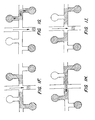
- Figure 1 A schematic illustration of this feature is illustrated in Figure 1 .
- Figure 1A schematically illustrates an intersection between two channels in a microfluidic device (not shown), e.g., a main analysis channel 100 and a sample loading channel 102.
- Sample loading channel also includes first and second sample introduction channels 104 and 106, respectively, in fluid communication with the sample loading channel on opposite sides of the intersection 108, and which sample introduction channels are also in fluid communication with first and second sample sources 110 and 112, respectively, e.g., a sample reservoir disposed in the device.
- the sample loading channel on each side of the intersection is also in fluid communication with first and second load/waste channels 114 and 116, respectively, which are in turn, in fluid communication with first and second load/waste reservoirs 118 and 120, respectively.
- Figures 1B to 1E schematically illustrate the sequential injection of a sample from each of the first and second sample wells.
- Figure 1B and 1C show the first sample (indicated by hatching) being drawn into the sample loading channel 102 and across the intersection 108 of the loading channel with the main channel 100, and into the second load/waste channel 116.
- electrical material direction systems e.g., E/O flow or electrophoretic transport systems as generally described herein
- this is accomplished by applying a voltage at the first sample reservoir 110 and the second load/waste reservoir 120, to achieve material movement along the path of current flow.
- the plug of sample material at the intersection is then injected into the main channel 100, by applying a voltage at points on the main channel on opposite sides of the intersection 108.
- the voltage applied at sample reservoir 110 and second load/waste reservoir 120 may be removed, e.g., allowing these reservoirs to 'float.'
- typically a voltage is maintained at these reservoirs, so as to achieve a net material flow away from the intersection, e.g., pulling the sample away from the intersection, to avoid any diffusion or leaking of the sample into the intersection during analysis.
- the second sample (indicated by cross-hatching) is loaded and injected into the main channel 104, in the same fashion as the first, as shown in Figures 1D and 1E . except that during loading, the voltages are applied at the second sample reservoir 112 and the first load/waste well 118.
- incorporation of load/waste reservoirs on both sides of the analysis channel also permits one sample to be preloaded while another sample is being analyzed in the analysis channel, as noted above.
- a sample is loaded into the separation channel by placing it in a reservoir at the terminus of the loading channel and applying a voltage across the loading channel until the sample has electrophoresed across the intersection of loading channel and the separation channel.
- the application of voltage is via an electrode disposed within the reservoir or well at the terminus of the given channel (also termed a "port").
- the plug of material at the intersection is then electrophoresed down the separation channel by applying a voltage gradient across the length of the analysis or separation channel.
- a subsequent sample may be transported to a location in the loading channel closer or even adjacent to the injection point.
- the sample is transported from its respective reservoir through a portion of the sample loading channel and to that load/waste channel/reservoir, without crossing the analysis channel.
- the voltages applied in this preloading procedure at levels such that the voltage at the preloading point, e.g., the intersection between load/waste channel 114 and loading channel 102, is substantially equal to that at the injection point (108), one can carry out this preloading without affecting the transportation of material within the analysis channel, e.g., without producing transverse electric fields between the loading channel and the analysis channel.
- V 1 V b + R b ⁇ V a - V b R a + R b
- R a is the resistance between the point at which V b is applied and the intermediate point at which V b is to be determined
- R b is the resistance between the point at which V b is applied and the intermediate point where V b is to be determined.
- the subsequent sample Upon completion of analysis of the previous sample, the subsequent sample, already within the sample loading channel, is then merely transported across the intersection of the loading channel and the analysis channel, and the plug of sample material at the intersection is then drawn down the analysis channel, as before.
- Figures 1F to 1I illustrate the same channel intersection structure shown in Figures 1B to 1E , but wherein that structure is used to preload one sample while a previous sample is being analyzed along the main channel.
- Figure 1F illustrates the post injection of the first sample e.g., as described with reference to Figures 1B to 1E , above.
- the second sample is transported into a position in the sample loading channel closer to the injection point, intersection 108, by moving the second sample into the sample loading channel and into the second load/waste channel.
- Figure 1G following the completion of the analysis of the first sample, e.g., electrophoretic separation. etc.
- the second sample is loaded into the analysis channel by drawing it across the intersection 108, and injecting it into the analysis channel Figure 1H ). This process is then repeated for all the samples that are to be analyzed.
- Figure 2 schematically illustrates the substantial time savings derived from sample preloading using the devices incorporating this preloading feature over devices not incorporating this feature.
- Panel A schematically illustrates the timing of events required to load and inject multiple samples into the analysis channel using a typical microfluidic device, i.e., which does not include a separate load/waste reservoir on each side of the analysis channel.
- loading any given sample requires the transportation of the sample across the intersection of the analysis channel and the loading channel, followed by the transportation of the sample plug at the intersection down the separation channel.
- no samples are loaded while a given sample is being analyzed, as this would result in the disturbance of the material flow in the analysis channel.
- analysis of one sample must be effectively completed prior to loading a subsequent sample, resulting in a sample loading and injection timeline where loading and analysis of samples does not overlap, as indicated by the arrows.
- Panel B of Figure 2 provides a similar timeline for samples serially analyzed in a device of the present invention, which incorporates an additional load/waste reservoir on the same side as the reservoirs containing the samples to be loaded. Incorporation of this additional load/waste reservoir allows the transporting of a sample from its respective reservoir into the loading channel, without crossing or otherwise affecting the material flow within the analysis channel, also termed "preloading.” As such, while one sample is being transported along the analysis channel and analyzed, a subsequent sample may be preloaded into the loading channel. As shown, the time savings can be substantial, particularly where multiple samples (e.g., 8, 10, 12, 16 or greater) are being analyzed.
- the load/waste channel In order to reduce the amount of dead volume between a preloaded sample and the analysis channel, it is generally desirable for the load/waste channel to intersect the sample loading channel at a point that is relatively close to the intersection of the loading channel and the analysis channel.
- the distance between these two intersections is typically less than 5 mm. preferably less than 2 mm, more preferably less than 1 mm, and often, less than 0.5 mm.
- each sample it is generally desirable to be able to preload each sample to the same point in the sample loading channel. This permits the standardization and simplification of timing for preloading, loading and injecting each sample. In addition, during this preloading time. a myriad of other operations may be performed on the sample, including dilution, combination with substrates or other reactants, and the like. As such, it is generally preferable for the load/waste channel to intersect the sample loading channel at a point between all of the sample reservoirs and the main channel. Thus, in preferred aspects. each load waste channel intersects the sample loading channel at a point between: (1) the intersection of the sample loading channel and the main channel, and (2) the intersection of the sample loading channel with each of the sample channels. Sample loading and preloading in these devices is described in greater detail below.
- the incorporation of multiple sample sources, each having a separate path, at least in part, to the injection point provides at least one additional advantage, particularly when that system is applied in CE applications.
- Typical CE systems introduce each sample that is being analyzed by identical paths, e.g., through the same sample well or via the same channel or passage. Often times, this can result in an accumulation within that path of extremely slowly migrating material. e.g., very large nucleic acid molecules or complexes, proteins etc., which accumulation can result in a general fouling of the separation channel or capillary.
- the microfluidic devices of the present invention optionally include channels that have narrower width dimensions, particularly at the injection point of the device.
- narrowing the dimensions at least at the injection intersection one can substantially reduce the size of the sample plug that is injected into the analysis channel, thereby providing a narrower band to detect, and thus, greater resolution between adjacent bands.
- Providing the analysis channel with narrower width dimensions also is particularly useful in systems employing laser fluorescent detection systems.
- narrowing the width of the injection channel and analysis channel to a range of from about 1X to about 5X of the laser spot size incident on the detection portion of the analysis channel, one increases resolution of the bands in the analysis channel, as described above, without substantially varying the sensitivity of the device.
- the detector is able to detect a greater percentage of that material.
- the analysis channel optionally has a width of from about 10 ⁇ m to about 50 ⁇ m, and preferably from about 20 ⁇ m to about 40 ⁇ m, and more preferably, about 30 to 35 ⁇ m.
- FIG. 3 An example of a device employing improved channel and reservoir geometries according to the present invention is shown in Figure 3 .
- the device 300 is fabricated from a planar substrate 302, which has the various channels fabricated into its surface.
- a second planar layer overlays the first and includes holes disposed through it to form the various reservoirs. This second planar element is then bonded to the first.
- the device includes a main separation or analysis channel 304 which runs longitudinally down the central portion of the substrate.
- the main channel 304 originates in and is in fluid communication with buffer reservoir 306, and terminates, and is in fluid communication with waste reservoirs 308 and 310, via waste channel 312.
- Sample loading channel 314 intersects and is in fluid communication with main channel 304.
- the device also includes multiple separate sample reservoirs 316 through 346, inclusive, each of which is in fluid communication with sample loading channel 314, either directly via its respective sample channels 348-378, or via an intermediate sample channel.
- Load/waste channels 380 and 382 are also provided, in fluid communication with sample loading channel 314, on opposite sides of the intersection of the sample loading channel with main channel 304, and between that intersection and the sample channels on their respective sides of that intersection. Each of these load/waste channels terminates in one of load/waste reservoirs 384 and 386, respectively.
- the multiple separate sample reservoirs are disposed on both sides of the main channel, in order to maximize the number of reservoirs that fit on the substrate, while minimizing the distance that a sample must travel to reach the analysis channel.
- an electrode is placed into electrical contact with each of reservoirs 306-310, 316-346, 384 and 386.
- electrophoretic transport and direction of materials in the device it will be readily appreciated that other forms of material transport and direction are also envisioned and would be equally benefitted by the present invention, e.g., electroosmotic fluid transport and direction, pressure or pneumatically driven fluid transport systems, including those utilizing micropumps, or other displacement driven systems.
- a first sample is disposed within a sample reservoir, e.g., reservoir 316.
- the sample is transported along sample channel 348 to loading channel 314, across the intersection of loading channel 314 and main channel 304, by application of an appropriate voltage at sample reservoir 316 and waste reservoir 386.
- appropriate voltages are also applied at buffer reservoir 306 and waste reservoirs 308 and 310, to apply a constraining flow of fluid from the main channel to "pinch" the flow of the sample across the intersection, thereby preventing leakage or diffusion of sample at the intersection. Pinched loading is described in detail in Published PCT Application No. WO 96/04547 .
- the sample plug e.g., the pinched plug
- the sample plug is then drawn down main channel 304, by applying a voltage between buffer reservoir 306 and waste reservoirs 308 and 310, while reservoirs 316 and 386 are allowed to float.
- appropriate voltages may be applied to these floating reservoirs in order to draw the sample in the loading channel away from the intersection, so as to avoid the leaking of a sample into the analysis channel.
- a second sample may be "preloaded” into position in loading channel 314 for subsequent analysis.
- This subsequent sample is preloaded from sample reservoir 318 into loading channel 314 and out through load/waste channel 380 to load/waste reservoir 384, by applying an appropriate voltage at sample reservoir 318 and load/waste reservoir 384.
- the voltages applied at these reservoirs are typically maintained at levels such that the voltage at the injection point (intersection of channels 304 and 314) is substantially equal to the voltage at the preload point (intersection of channel 314 and 382), so as to avoid the generation of transverse fields, i.e., a voltage gradient, between the loading channel and the main channel during the preloading procedure.
- each side of the main channel includes a separate "preloading module" that includes the collection of sample reservoirs and channels, in fluid communication with a sample loading channel.
- Each preloading module includes its own load/waste reservoir and channel in fluid communication with the sample loading channel, whereby a sample can be transported from its respective reservoir into the loading channel and to a position in the loading channel that is proximal to the intersection of the loading channel and the main channel, without affecting the movement of material in the main channel.
- the load/waste channel for a preloading module e.g., load/waste channel 380, intersect its loading channel, e.g., 314, at a point close to the intersection of the loading channel and the main channel.
- FIG. 4 A similar channel/reservoir geometry is illustrated in Figure 4 , for a device which includes 12 separate sample reservoirs, as well as the preloading features described above.
- the buffer reservoir 306, waste reservoir 310 and load/waste reservoirs 384 and 386 are located in a row at the bottom of the device. This results in a gridded array of sample/waste/buffer reservoirs. wherein a twelve sample device only occupies approximately one half of the substrate area required for the device shown in Figure 3 .
- this device includes fewer sample reservoirs than the device illustrated in Figure 3 and described above, the sample area ratio is substantially increased by optimizing the channel and reservoir geometry.
- the device shown in Figure 4 has side dimensions of 17.5 mm (e.g., 17.5 mm X 17.5 mm), one can obtain 49 separate devices from a single 5" X 5" square substrate plate or wafer, permitting analysis of 588 samples per plate. Assuming the device shown in Figure 3 is 22.4 mm X 37 5 mm, one can only obtain 15 separate devices or 240 assays per substrate plate.
- the devices, systems and methods of the present invention are not limited in application to capillary electrophoresis applications, but may be broadly applied to the field of microfluidics. including fluidic systems employing a variety of material transport mechanisms, including, e.g., electroosmotic transport systems, electrophoretic transport systems and even pressure driven systems.
- material transport mechanisms including, e.g., electroosmotic transport systems, electrophoretic transport systems and even pressure driven systems.
- electroosmotic transport systems e.g., electrophoretic transport systems and even pressure driven systems.
- the channels of the device are pretreated with a dynamic sieving matrix.
- dynamic seiving matrices typically comprise charged polymers, e.g., linear polyacrylamide polymers, which are capable of binding the walls of the capillary channels, thereby shielding the charged surfaces of these walls, and reducing electroosmotic flow.
- Examples of particularly preferred dynamic sieving matrices include those discussed in U.S. Patent No. 5,264,101 , as well as the GeneScanTM sieving buffers available from Perkin Elmer Corp.
- FIG. 5 A device incorporating an alternate channel geometry according to the present invention is illustrated in Figure 5 .
- the device includes a channel geometry that is similar to that shown in Figure 4 .
- the microfluidic device 500 fabricated from substrate 502 includes main channel 504 that has disposed at its termini buffer reservoir 506 and waste reservoir 508.
- Main channel 504 is intersected by and in fluid communication with first ends of sample loading channels 512 and 514 (on the left and right sides respectively, as shown).
- Sample channel 512 is in fluid communication at its second end with sample reservoirs 516-526, via sample channels 542-550, respectively, whereas sample loading channel 514 is in fluid communication at its second end with sample reservoirs 528-538 via sample channels 552-562, respectively.
- Sample preload waste channels 582 and 584 intersect sample loading channels 512 and 514, respectively, at points proximal to the injection point or intersection.
- the device illustrated performs substantially the same operations as the devices shown in Figures 3 and 4 .
- the device 500 includes sample channels 540-562 that are of substantially equal lengths, from their respective reservoirs to the point at which they intersect their respective sample loading channel (512 or 514).
- the device shown provides all of the advantages delineated above.
- sample loading channels 512 and 514 with their respective sample/preload channels 582 and 584 are placed closer to the intersection of these channels with their respective sample channels, e.g., 540-550 and 552-562, respectively, in order to minimize the length of the sample loading channels and thereby reduce the possibility of cross-contamination of samples during preloading.
- this loading channel length between these intersections is less than about 5 mm, and preferably, less than about 2 mm.
- the devices and systems described herein may generally he used in the analysis of chemical and biochemical materials.
- the present invention provides for the use of such devices and systems in separating component elements of the sample materials, e.g., nucleic acids, proteins, or other macromolecular species, as well as differentially charged materials.
- the devices of the present invention are optionally provided in kits.
- kits of the invention optionally comprise one or more of the following: (1) an apparatus or apparatus component as described herein, e.g., the microfluidic device(s) described above); (2) instructions for practicing the methods described herein, and/or for operating the apparatus or apparatus components herein; (3) one or more assay component(s), e.g., reagents, fluorescent dyes, standards, sieving matrices or the like; (4) a container for holding apparatus or assay components, and, (5) packaging materials.
- microfluidic devices are typically placed in an electrical controller unit that disposes an electrode in each of the reservoirs of the device to carry out the operations of the device, as described herein.
- the controller unit delivers appropriate currents through the electrodes that are in contact with the reservoirs of the device, in order to direct material through the channels of the device.
- the currents delivered by the controller are typically current and time profiles for each electrode that are entered into a computer by a user, which computer is operably connected to the controller.
- the computer then instructs the controller in the application of currents to the various electrodes to move material through the channels of the device in a controlled manner, e.g., providing sufficient current levels to achieve contolled electrokinetic material transport, as described above.
- a 16 sample capacity device, or LabChipTM, having the geometry shown in Figure 3 was fabricated from a 100 mm diameter white crown glass wafer having a thickness of 500 ⁇ m. A wafer was used for its compatibility with most commercially available photolithography equipment. Channels 75 ⁇ m wide and 12 ⁇ m deep, and having the configuration shown, were etched in the glass substrate using standard photolithographic techniques. Holes were drilled through a separate piece of glass 5 inches on a side, whereby the holes corresponded to the termini of the various channels. The two pieces of glass were thermally bonded to form the channel and well structure shown. The device having dimensions of 22.4 mm X 37 mm was cut from the larger material.
- Sieving buffer was prepared by weighing 2.5 grams GeneScan Polymer (Perkin Elmer Corp.), 0.5 g of Genetic Analysis Buffer (Perkin Elmer Corp.) and 2.5 ml water into a 20 ml scintillation vial, which was then vortexed for 30 seconds.
- One ⁇ l of Syber Green I DNA intercalation dye (Molecular Probes Inc.) was added to 0.5 ml of the sieving buffer which was again vortexed for 30 seconds in a 1.5 ml Eppendorf tube.
- Five ⁇ l PCR Marker (Promega Corp.) containing 6 DNA fragments ranging in size from 50 to 1000 bp was mixed with 15 ⁇ l of the buffer containing the Syber Green and vortexed.
- the channels in the LabChipTM were filled with 3.5% GeneScanTM buffer (Perkin-Elmer Corp.) by applying 5 ⁇ l to the buffer well and then applying slight pressure with a syringe for 5 seconds on the well.
- This buffer contains a polymer which retards the migration of DNA relative to its size and also modifies the walls of the channel to reduce electroosmotic flow.
- Four ⁇ l of the GeneScan buffer was then added to the buffer and waste wells.
- a DNA standard, PhiX174 cleaved with HinfI was diluted 50:1 in 3.5% GeneScanTM buffer containing 1 ⁇ M SyberGreen DNA intercalating dye (Molecular Probes, Inc.) and 4 ⁇ l of this solution was added to each of the 16 sample wells.
- the device was then placed under a Nikon inverted Microscope Diaphot 200, with a PTI Model 814 PMT detection system, for epifluorescent detection.
- An Opti-Quip 1200-1500 50W tungsten/halogen lamp coupled through a 40X microscope objective provided the light source. Excitation and emission wavelengths were selected with a FITC filter cube (Chroma, Brattleboro VT) fitted with appropriate filters/dichroic mirrors.
- Reagent well currents and voltages on the chip were controlled using a voltage controller having a separate controllable electrode for each of the separate reservoirs on the microfluidic device.
- the serial injection of samples proceeded along the following cycle:
- the voltage applied to main buffer reservoir 306 was controlled at a level at which it provided an appropriate balancing current in the remainder of the system: Table 1 Step Sample Well Sample Current ( ⁇ A) Load/Waste Well Load/Waste Current ( ⁇ A) Buffer Well Waste Current ( ⁇ A) 1 332 -7 386 10 310 -2 2 332 -7 384 10 310 -2 3 332 5 384 5 308 -12 4 332 1 384 1 308 -8 5 334 -7 386 10 308 -7.5 6 334 -7 384 10 310 -2
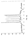
- Figures 7A , 7B and 7C show plots of successive injections of PCR Marker, PhiX174/HaeIII and buffer blanks.
- Figure 7B illustrates that no spurious fluorescence peaks are detectable bleeding over from the previous PCR Marker run, into the PhiX174/HaeIII run.
- Figure 7C shows that even in a plain buffer run, there are no detectable levels of cross contamination from the prior DNA containing samples.
- a microfluidic device incorporating the channel geometry shown in Figure 5 was prepared as described in Example 1, above, except that the width of all channels of the device was reduced to 30 ⁇ m, while the channel depth was maintained at approximately 12 ⁇ m. This was used to compare with a microfluidic device having the geometry shown in Figure 4 , but having channel widths of approximately 70 ⁇ m, as described in Example 1. The length of the separation channels in the two devices was substantially equivalent.
Landscapes
- Chemical & Material Sciences (AREA)
- Health & Medical Sciences (AREA)
- Dispersion Chemistry (AREA)
- Life Sciences & Earth Sciences (AREA)
- Chemical Kinetics & Catalysis (AREA)
- Analytical Chemistry (AREA)
- General Health & Medical Sciences (AREA)
- Molecular Biology (AREA)
- Clinical Laboratory Science (AREA)
- Hematology (AREA)
- Electrochemistry (AREA)
- Immunology (AREA)
- Pathology (AREA)
- General Physics & Mathematics (AREA)
- Biochemistry (AREA)
- Physics & Mathematics (AREA)
- Automatic Analysis And Handling Materials Therefor (AREA)
- Investigating Or Analyzing Non-Biological Materials By The Use Of Chemical Means (AREA)
- Physical Or Chemical Processes And Apparatus (AREA)
- Apparatus Associated With Microorganisms And Enzymes (AREA)
- Measuring Or Testing Involving Enzymes Or Micro-Organisms (AREA)
Claims (3)
- Dispositif microfluidique, comprenant :une structure de corps présentant une partie interne et une partie externe ;un canal d'analyse [100, 304] agencé dans la partie interne ;un canal de chargement d'échantillons [102, 314] croisant le canal d'analyse au niveau d'une première intersection ;un premier réservoir d'échantillons [110, 316] connecté au canal de chargement d'échantillons par le biais d'un premier canal d'échantillons [104, 348], le premier canal d'échantillons croisant le canal de chargement d'échantillons au niveau d'une deuxième intersection ;un second réservoir d'échantillons [112, 340] connecté au canal de chargement d'échantillons par le biais d'un second canal d'échantillons [106, 372], le second canal d'échantillons croisant le canal de chargement d'échantillons au niveau d'une troisième intersection, les deuxième et troisième intersections étant situées sur différents côtés de la première intersection ;un premier réservoir de charge / rebut [118, 384] connecté au canal de chargement d'échantillons par le biais d'un premier canal de charge / rebut [114, 380], ledit premier canal de charge / rebut croisant le canal de chargement d'échantillons au niveau d'une quatrième intersection, la quatrième intersection étant située entre la deuxième intersection et la première intersection ;un second réservoir de charge / rebut [120, 386] connecté au canal de chargement d'échantillons par le biais d'un second canal de charge / rebut [116, 382], ledit second canal de charge / rebut croisant le canal de chargement d'échantillons au niveau d'une cinquième intersection, la cinquième intersection étant située entre la troisième intersection et la première intersection ; etun système d'orientation de matériaux pour transporter individuellement un échantillon, du premier réservoir d'échantillons au premier réservoir de charge / rebut, par le biais du canal de chargement d'échantillons, et du second réservoir d'échantillons au second réservoir de charge /rebut, par le biais du canal de chargement d'échantillons, et pour injecter sélectivement les échantillons dans le canal d'analyse.
- Dispositif microfluidique selon la revendication 1, dans lequel un échantillon provenant de chacune desdites première et seconde sources d'échantillons est transporté vers lesdits premier et second canaux de charge / rebut par l'intermédiaire dudit canal de chargement d'échantillons, sans croiser le canal d'analyse.
- Procédé de mise en oeuvre d'analyse sur une pluralité de matériaux d'échantillons différents, comprenant :la fourniture d'un dispositif microfluidique comportant :une structure de corps planaire présentant une partie externe et une partie interne ;un canal d'analyse agencé dans ladite partie interne ;un canal de chargement d'échantillons agencé dans ladite partie interne et croisant ledit canal d'analyse au niveau d'une première intersection ; etau moins des premier et second réservoirs d'échantillons et un réservoir de rebut agencés dans ladite structure de corps, dans lequel ladite pluralité de réservoirs d'échantillons et ledit réservoir de rebut sont connectés audit canal de chargement d'échantillons par le biais de canaux qui croisent ledit canal de chargement d'échantillons ;le transport d'un premier échantillon, dudit premier réservoir d'échantillons vers ladite première intersection ;l'injection d'une partie dudit premier échantillon dans ledit canal d'analyse ;l'analyse de ladite partie dudit premier échantillon dans ledit canal d'analyse, et simultanément, le transport d'un second échantillon dudit second réservoir d'échantillons à travers ledit canal de chargement d'échantillons, et ensuite vers ledit réservoir de rebut, sans croiser le canal d'analyse ;le transport dudit second échantillon, dudit canal de chargement vers ladite intersection ;l'injection d'une partie dudit second échantillon dans ledit canal d'analyse ; etl'analyse de ladite partie dudit second échantillon dans ledit canal d'analyse.
Priority Applications (1)
| Application Number | Priority Date | Filing Date | Title |
|---|---|---|---|
| EP10009625A EP2259053A3 (fr) | 1997-04-25 | 1998-04-13 | Dispositifs microfluidiques a geométrie de canaux ameliorée |
Applications Claiming Priority (5)
| Application Number | Priority Date | Filing Date | Title |
|---|---|---|---|
| US845754 | 1997-04-25 | ||
| US08/845,754 US5976336A (en) | 1997-04-25 | 1997-04-25 | Microfluidic devices incorporating improved channel geometries |
| US6090297P | 1997-10-03 | 1997-10-03 | |
| US60902P | 1997-10-03 | ||
| PCT/US1998/007444 WO1998049548A1 (fr) | 1997-04-25 | 1998-04-13 | Dispositifs microfluidiques a geometrie de canaux amelioree |
Related Child Applications (1)
| Application Number | Title | Priority Date | Filing Date |
|---|---|---|---|
| EP10009625.4 Division-Into | 2010-09-15 |
Publications (3)
| Publication Number | Publication Date |
|---|---|
| EP0988529A1 EP0988529A1 (fr) | 2000-03-29 |
| EP0988529A4 EP0988529A4 (fr) | 2001-02-07 |
| EP0988529B1 true EP0988529B1 (fr) | 2013-06-12 |
Family
ID=26740479
Family Applications (1)
| Application Number | Title | Priority Date | Filing Date |
|---|---|---|---|
| EP98918182.1A Expired - Lifetime EP0988529B1 (fr) | 1997-04-25 | 1998-04-13 | Dispositifs microfluidiques a geometrie de canaux amelioree |
Country Status (8)
| Country | Link |
|---|---|
| US (3) | US6235175B1 (fr) |
| EP (1) | EP0988529B1 (fr) |
| JP (1) | JP4171075B2 (fr) |
| KR (1) | KR100351531B1 (fr) |
| CN (1) | CN1105914C (fr) |
| AU (1) | AU727083B2 (fr) |
| CA (1) | CA2287409C (fr) |
| WO (1) | WO1998049548A1 (fr) |
Families Citing this family (397)
| Publication number | Priority date | Publication date | Assignee | Title |
|---|---|---|---|---|
| EP0620432B1 (fr) * | 1993-04-15 | 2004-08-25 | Zeptosens AG | Méthode pour contrôler l'introduction d'un échantillon en séparation par micro colonnes et appareil d'échantillonage |
| US7824532B2 (en) * | 1995-04-26 | 2010-11-02 | Life Technologies Corporation | Apparatus and method for electrophoresis |
| US6048734A (en) | 1995-09-15 | 2000-04-11 | The Regents Of The University Of Michigan | Thermal microvalves in a fluid flow method |
| US5885470A (en) | 1997-04-14 | 1999-03-23 | Caliper Technologies Corporation | Controlled fluid transport in microfabricated polymeric substrates |
| US5942443A (en) | 1996-06-28 | 1999-08-24 | Caliper Technologies Corporation | High throughput screening assay systems in microscale fluidic devices |
| CN1173776C (zh) | 1996-06-28 | 2004-11-03 | 卡钳技术有限公司 | 在微规模流体性设备里的高通过量的筛选分析系统 |
| US7070590B1 (en) * | 1996-07-02 | 2006-07-04 | Massachusetts Institute Of Technology | Microchip drug delivery devices |
| US7033474B1 (en) | 1997-04-25 | 2006-04-25 | Caliper Life Sciences, Inc. | Microfluidic devices incorporating improved channel geometries |
| WO1998049548A1 (fr) * | 1997-04-25 | 1998-11-05 | Caliper Technologies Corporation | Dispositifs microfluidiques a geometrie de canaux amelioree |
| EP1021566A4 (fr) | 1997-06-09 | 2002-06-19 | Caliper Techn Corp | Dispositifs et procedes pour la correction des variations de vitesse dans les systemes microfluidiques |
| US6368871B1 (en) * | 1997-08-13 | 2002-04-09 | Cepheid | Non-planar microstructures for manipulation of fluid samples |
| US5989402A (en) | 1997-08-29 | 1999-11-23 | Caliper Technologies Corp. | Controller/detector interfaces for microfluidic systems |
| US7632651B2 (en) | 1997-09-15 | 2009-12-15 | Mds Analytical Technologies (Us) Inc. | Molecular modification assays |
| US7745142B2 (en) | 1997-09-15 | 2010-06-29 | Molecular Devices Corporation | Molecular modification assays |
| EP1179585B1 (fr) | 1997-12-24 | 2008-07-09 | Cepheid | Dispositif et procédé de Lyse |
| EP1044370B1 (fr) * | 1997-12-30 | 2017-08-23 | Caliper Life Sciences, Inc. | Logiciel pour l'affichage de donnees de separation en chromatographie |
| US6756019B1 (en) | 1998-02-24 | 2004-06-29 | Caliper Technologies Corp. | Microfluidic devices and systems incorporating cover layers |
| US6251343B1 (en) | 1998-02-24 | 2001-06-26 | Caliper Technologies Corp. | Microfluidic devices and systems incorporating cover layers |
| US7497994B2 (en) | 1998-02-24 | 2009-03-03 | Khushroo Gandhi | Microfluidic devices and systems incorporating cover layers |
| US6123798A (en) * | 1998-05-06 | 2000-09-26 | Caliper Technologies Corp. | Methods of fabricating polymeric structures incorporating microscale fluidic elements |
| CA2320296A1 (fr) | 1998-05-18 | 1999-11-25 | University Of Washington | Cartouche d'analyse liquide |
| US6830729B1 (en) | 1998-05-18 | 2004-12-14 | University Of Washington | Sample analysis instrument |
| US6306590B1 (en) | 1998-06-08 | 2001-10-23 | Caliper Technologies Corp. | Microfluidic matrix localization apparatus and methods |
| EP1084391A4 (fr) | 1998-06-08 | 2006-06-14 | Caliper Life Sciences Inc | Dispositifs microfluidiques, systemes et procedes pour realiser des reactions et des separations integrees |
| US20030138973A1 (en) * | 1998-07-14 | 2003-07-24 | Peter Wagner | Microdevices for screening biomolecules |
| US6794197B1 (en) * | 1998-07-14 | 2004-09-21 | Zyomyx, Inc. | Microdevice and method for detecting a characteristic of a fluid |
| US6576478B1 (en) * | 1998-07-14 | 2003-06-10 | Zyomyx, Inc. | Microdevices for high-throughput screening of biomolecules |
| US6447724B1 (en) | 1998-08-11 | 2002-09-10 | Caliper Technologies Corp. | DNA sequencing using multiple fluorescent labels being distinguishable by their decay times |
| US6716394B2 (en) | 1998-08-11 | 2004-04-06 | Caliper Technologies Corp. | DNA sequencing using multiple fluorescent labels being distinguishable by their decay times |
| US6637463B1 (en) | 1998-10-13 | 2003-10-28 | Biomicro Systems, Inc. | Multi-channel microfluidic system design with balanced fluid flow distribution |
| US6591852B1 (en) | 1998-10-13 | 2003-07-15 | Biomicro Systems, Inc. | Fluid circuit components based upon passive fluid dynamics |
| US6601613B2 (en) | 1998-10-13 | 2003-08-05 | Biomicro Systems, Inc. | Fluid circuit components based upon passive fluid dynamics |
| EP1125129A1 (fr) | 1998-10-13 | 2001-08-22 | Biomicro Systems, Inc. | Composants de circuit fluidique bases sur la dynamique passive des fluides |
| US6149787A (en) | 1998-10-14 | 2000-11-21 | Caliper Technologies Corp. | External material accession systems and methods |
| EP0999443A3 (fr) * | 1998-11-02 | 2002-09-18 | The Institute of Physical and Chemical Research | Appareil d'électrophorèse capillaire, plaquette-échantillon, et procédé d'injection d'échantillon |
| US6431476B1 (en) | 1999-12-21 | 2002-08-13 | Cepheid | Apparatus and method for rapid ultrasonic disruption of cells or viruses |
| US7914994B2 (en) | 1998-12-24 | 2011-03-29 | Cepheid | Method for separating an analyte from a sample |
| US6416642B1 (en) | 1999-01-21 | 2002-07-09 | Caliper Technologies Corp. | Method and apparatus for continuous liquid flow in microscale channels using pressure injection, wicking, and electrokinetic injection |
| US20020019059A1 (en) * | 1999-01-28 | 2002-02-14 | Calvin Y.H. Chow | Devices, systems and methods for time domain multiplexing of reagents |
| CN1296703C (zh) * | 1999-02-02 | 2007-01-24 | 卡钳生命科学股份有限公司 | 鉴定蛋白质的方法、装置和系统 |
| ATE556149T1 (de) | 1999-02-23 | 2012-05-15 | Caliper Life Sciences Inc | Manipulation von mikropartikeln in mikrofluidischen systemen |
| US6749814B1 (en) | 1999-03-03 | 2004-06-15 | Symyx Technologies, Inc. | Chemical processing microsystems comprising parallel flow microreactors and methods for using same |
| US6326083B1 (en) | 1999-03-08 | 2001-12-04 | Calipher Technologies Corp. | Surface coating for microfluidic devices that incorporate a biopolymer resistant moiety |
| US7247490B2 (en) * | 1999-04-06 | 2007-07-24 | Uab Research Foundation | Method for screening crystallization conditions in solution crystal growth |
| US7250305B2 (en) * | 2001-07-30 | 2007-07-31 | Uab Research Foundation | Use of dye to distinguish salt and protein crystals under microcrystallization conditions |
| US6303343B1 (en) | 1999-04-06 | 2001-10-16 | Caliper Technologies Corp. | Inefficient fast PCR |
| US20030022383A1 (en) * | 1999-04-06 | 2003-01-30 | Uab Research Foundation | Method for screening crystallization conditions in solution crystal growth |
| US7214540B2 (en) * | 1999-04-06 | 2007-05-08 | Uab Research Foundation | Method for screening crystallization conditions in solution crystal growth |
| WO2000062050A1 (fr) * | 1999-04-09 | 2000-10-19 | The University Of Manchester Institute Of Science & Technology | Procede d'electrophorese et appareil a injection d'echantillon a modulation temporelle ou spatiale |
| US6375817B1 (en) * | 1999-04-16 | 2002-04-23 | Perseptive Biosystems, Inc. | Apparatus and methods for sample analysis |
| US6555389B1 (en) * | 1999-05-11 | 2003-04-29 | Aclara Biosciences, Inc. | Sample evaporative control |
| US6458259B1 (en) | 1999-05-11 | 2002-10-01 | Caliper Technologies Corp. | Prevention of surface adsorption in microchannels by application of electric current during pressure-induced flow |
| US6592821B1 (en) | 1999-05-17 | 2003-07-15 | Caliper Technologies Corp. | Focusing of microparticles in microfluidic systems |
| EP1179087B1 (fr) | 1999-05-17 | 2019-03-27 | Caliper Life Sciences, Inc. | Focalisation de microparticules dans des systemes microfluidiques |
| US6287774B1 (en) * | 1999-05-21 | 2001-09-11 | Caliper Technologies Corp. | Assay methods and system |
| US6472141B2 (en) | 1999-05-21 | 2002-10-29 | Caliper Technologies Corp. | Kinase assays using polycations |
| DE60022025T2 (de) | 1999-05-28 | 2006-06-29 | Cepheid, Sunnyvale | Anlage zum brechen von zellen |
| US9073053B2 (en) | 1999-05-28 | 2015-07-07 | Cepheid | Apparatus and method for cell disruption |
| US20040200909A1 (en) * | 1999-05-28 | 2004-10-14 | Cepheid | Apparatus and method for cell disruption |
| US8815521B2 (en) | 2000-05-30 | 2014-08-26 | Cepheid | Apparatus and method for cell disruption |
| EP1185871A4 (fr) | 1999-06-01 | 2003-01-15 | Caliper Techn Corp | Dosages a micro-echelle et dispositifs microfluidiques destines au controle des activites de transporteur, de gradient induit et de liaison |
| DE19928412C2 (de) * | 1999-06-22 | 2002-03-21 | Agilent Technologies Inc | Versorgungselement für einen Labor-Mikrochip |
| US6878540B2 (en) * | 1999-06-25 | 2005-04-12 | Cepheid | Device for lysing cells, spores, or microorganisms |
| WO2001002850A1 (fr) | 1999-07-06 | 2001-01-11 | Caliper Technologies Corp. | Systemes et methodes microfluidiques permettant de determiner la cinetique d'un modulateur |
| US6579726B1 (en) | 1999-07-30 | 2003-06-17 | Surromed, Inc. | Instruments, methods and reagents for surface plasmon resonance |
| US7138254B2 (en) * | 1999-08-02 | 2006-11-21 | Ge Healthcare (Sv) Corp. | Methods and apparatus for performing submicroliter reactions with nucleic acids or proteins |
| US6858185B1 (en) | 1999-08-25 | 2005-02-22 | Caliper Life Sciences, Inc. | Dilutions in high throughput systems with a single vacuum source |
| US6613581B1 (en) | 1999-08-26 | 2003-09-02 | Caliper Technologies Corp. | Microfluidic analytic detection assays, devices, and integrated systems |
| WO2001027253A1 (fr) | 1999-10-08 | 2001-04-19 | Caliper Technologies Corp. | Utilisation de teintures sensibles au potentiel de nernst pour mesurer le potentiel transmembranaire |
| DE19949551C2 (de) | 1999-10-14 | 2001-12-13 | Agilent Technologies Inc | Mikrofluidischer Mikrochip, Energieversorgungseinrichtung und Verfahren zum Betrieb eines mikrofluidischen Mikrochips |
| US7157284B2 (en) * | 1999-10-29 | 2007-01-02 | The United States Of America As Represented By The Environmental Protection Agency | Vacuum distillation automatic sampler |
| US6878255B1 (en) | 1999-11-05 | 2005-04-12 | Arrowhead Center, Inc. | Microfluidic devices with thick-film electrochemical detection |
| JP2003514224A (ja) * | 1999-11-12 | 2003-04-15 | サーロメッド・インコーポレーテッド | 表面プラズモン共鳴を使用するバイオセンシング |
| US6149815A (en) * | 1999-11-23 | 2000-11-21 | Sauter; Andrew D. | Precise electrokinetic delivery of minute volumes of liquid(s) |
| US6271038B1 (en) * | 1999-12-15 | 2001-08-07 | Glaxo Wellcome Inc. | Methods for high throughout determination and ranking of formulations and solubility |
| US6468761B2 (en) | 2000-01-07 | 2002-10-22 | Caliper Technologies, Corp. | Microfluidic in-line labeling method for continuous-flow protease inhibition analysis |
| US7037416B2 (en) | 2000-01-14 | 2006-05-02 | Caliper Life Sciences, Inc. | Method for monitoring flow rate using fluorescent markers |
| US6685813B2 (en) | 2000-02-11 | 2004-02-03 | Aclara Biosciences, Inc. | Tandem isotachophoresis/zone electrophoresis method and system |
| AU2001234997B2 (en) * | 2000-02-11 | 2006-07-27 | Monogram Biosciences, Inc. | Microfluid device with sample injector and method of use |
| US7040144B2 (en) * | 2000-02-23 | 2006-05-09 | Caliper Life Sciences, Inc. | Microfluidic viscometer |
| ATE382858T1 (de) * | 2000-02-23 | 2008-01-15 | Caliper Life Sciences Inc | Mehrfach-reservoir-drucksteuersystem |
| US6681616B2 (en) * | 2000-02-23 | 2004-01-27 | Caliper Technologies Corp. | Microfluidic viscometer |
| US6454924B2 (en) * | 2000-02-23 | 2002-09-24 | Zyomyx, Inc. | Microfluidic devices and methods |
| GB2359765B (en) * | 2000-03-02 | 2003-03-05 | Univ Newcastle | Capillary reactor distribution device and method |
| DE60144142D1 (de) * | 2000-03-02 | 2011-04-14 | Microchips Inc | Mikromechanische geräte und verfahren zur speicherung und zur selektiven exposition von chemikalien |
| US7485454B1 (en) | 2000-03-10 | 2009-02-03 | Bioprocessors Corp. | Microreactor |
| US20020012971A1 (en) | 2000-03-20 | 2002-01-31 | Mehta Tammy Burd | PCR compatible nucleic acid sieving medium |
| US6358387B1 (en) * | 2000-03-27 | 2002-03-19 | Caliper Technologies Corporation | Ultra high throughput microfluidic analytical systems and methods |
| JP2001281233A (ja) * | 2000-03-28 | 2001-10-10 | Inst Of Physical & Chemical Res | 水性分配用マイクロチップおよびそれを用いた水性分配方法 |
| WO2001075415A2 (fr) * | 2000-03-31 | 2001-10-11 | Micronics, Inc. | Cristallisation de proteines dans des structures microfluidiques |
| US6733645B1 (en) | 2000-04-18 | 2004-05-11 | Caliper Technologies Corp. | Total analyte quantitation |
| AU6154101A (en) | 2000-05-11 | 2001-11-20 | Caliper Techn Corp | Microfluidic devices and methods to regulate hydrodynamic and electrical resistance utilizing bulk viscosity enhancers |
| AU2001261523B2 (en) * | 2000-05-12 | 2005-11-17 | Caliper Life Sciences, Inc. | Detection of nucleic acid hybridization by fluorescence polarization |
| WO2001089691A2 (fr) * | 2000-05-24 | 2001-11-29 | Micronics, Inc. | Capillaires permettant le mouvement de fluide dans des canaux microfluidiques |
| GB2362713A (en) * | 2000-05-26 | 2001-11-28 | Casect Ltd | Sampling system for gas |
| AU2001265128A1 (en) | 2000-05-30 | 2001-12-11 | Massachusetts Institute Of Technology | Methods and devices for sealing microchip reservoir devices |
| US7062418B2 (en) * | 2000-06-27 | 2006-06-13 | Fluidigm Corporation | Computer aided design method and system for developing a microfluidic system |
| US6885982B2 (en) * | 2000-06-27 | 2005-04-26 | Fluidigm Corporation | Object oriented microfluidic design method and system |
| DE10035911A1 (de) * | 2000-07-21 | 2002-02-07 | Abb Research Ltd | Verfahren und Sensor zum Überwachen von Flüssigkeiten |
| EP1314024A4 (fr) * | 2000-08-02 | 2007-04-11 | Caliper Life Sciences Inc | Systemes d'analyse bases sur les separations, a haut rendement |
| US20070119711A1 (en) * | 2000-08-02 | 2007-05-31 | Caliper Life Sciences, Inc. | High throughput separations based analysis systems and methods |
| AU2001284700B2 (en) * | 2000-08-03 | 2005-12-08 | Caliper Life Sciences, Inc. | Methods and devices for high throughput fluid delivery |
| WO2002012856A1 (fr) * | 2000-08-04 | 2002-02-14 | Caliper Technologies Corp. | Controle des conditions de fonctionnement dans des systemes fluidiques |
| US20020142618A1 (en) * | 2000-08-04 | 2002-10-03 | Caliper Technologies Corp. | Control of operation conditions within fluidic systems |
| US6615856B2 (en) * | 2000-08-04 | 2003-09-09 | Biomicro Systems, Inc. | Remote valving for microfluidic flow control |
| GB0019500D0 (en) | 2000-08-08 | 2000-09-27 | Diamond Optical Tech Ltd | System and method |
| GB0019499D0 (en) * | 2000-08-08 | 2000-09-27 | Diamond Optical Tech Ltd | system and method |
| GB0019496D0 (en) | 2000-08-08 | 2000-09-27 | Diamond Optical Tech Ltd | System and method |
| US6562213B1 (en) | 2000-08-30 | 2003-05-13 | Ethrog Biotechnology Ltd. | Electrophoresis apparatus for simultaneous loading of multiple samples |
| EP1327132A4 (fr) * | 2000-09-21 | 2004-03-31 | Dna Sciences Inc | Procede et systeme servant a injecter un specimen |
| EP1336097A4 (fr) * | 2000-10-13 | 2006-02-01 | Fluidigm Corp | Systeme d'injection d'echantillons utilisant un dispositif microfluidique, pour dispositifs d'analyse |
| ATE336298T1 (de) * | 2000-10-25 | 2006-09-15 | Boehringer Ingelheim Micropart | Mikrostrukturierte plattform für die untersuchung einer flüssigkeit |
| US8231845B2 (en) * | 2000-10-25 | 2012-07-31 | Steag Microparts | Structures for uniform capillary flow |
| EP1339496B1 (fr) * | 2000-11-06 | 2007-02-28 | The Government of the United States of America, as represented by the Secretary of Health and Human Services | Systeme d'apport d'echantillon comportant un melange laminaire pour la biodetection de microvolumes |
| US20090118139A1 (en) | 2000-11-07 | 2009-05-07 | Caliper Life Sciences, Inc. | Microfluidic method and system for enzyme inhibition activity screening |
| US8900811B2 (en) | 2000-11-16 | 2014-12-02 | Caliper Life Sciences, Inc. | Method and apparatus for generating thermal melting curves in a microfluidic device |
| US6942778B1 (en) * | 2000-11-28 | 2005-09-13 | Nanogen, Inc. | Microstructure apparatus and method for separating differently charged molecules using an applied electric field |
| US7070682B2 (en) * | 2001-01-16 | 2006-07-04 | Cheng Lee | Microfluidic apparatus for performing gel protein extractions and methods for using the apparatus |
| US7070681B2 (en) * | 2001-01-24 | 2006-07-04 | The Board Of Trustees Of The Leland Stanford Junior University | Electrokinetic instability micromixer |
| WO2002060754A1 (fr) * | 2001-01-29 | 2002-08-08 | Caliper Technologies Corp. | Vannes non mecaniques pour systemes fluidiques |
| US20020100714A1 (en) * | 2001-01-31 | 2002-08-01 | Sau Lan Tang Staats | Microfluidic devices |
| AU2002256998A1 (en) * | 2001-02-09 | 2002-09-19 | Microchem Solutions | Apparatus and method for small-volume fluid manipulation and transportation |
| US6875403B2 (en) | 2001-02-09 | 2005-04-05 | Microchem Solutions | Method and apparatus for reproducible sample injection on microfabricated devices |
| US6692700B2 (en) | 2001-02-14 | 2004-02-17 | Handylab, Inc. | Heat-reduction methods and systems related to microfluidic devices |
| JP2004527739A (ja) * | 2001-03-08 | 2004-09-09 | エスログ・バイオテクノロジー・リミテッド | 電気泳動のための装置及び方法 |
| US8895311B1 (en) | 2001-03-28 | 2014-11-25 | Handylab, Inc. | Methods and systems for control of general purpose microfluidic devices |
| US7010391B2 (en) * | 2001-03-28 | 2006-03-07 | Handylab, Inc. | Methods and systems for control of microfluidic devices |
| US6852287B2 (en) * | 2001-09-12 | 2005-02-08 | Handylab, Inc. | Microfluidic devices having a reduced number of input and output connections |
| US7323140B2 (en) | 2001-03-28 | 2008-01-29 | Handylab, Inc. | Moving microdroplets in a microfluidic device |
| US7829025B2 (en) | 2001-03-28 | 2010-11-09 | Venture Lending & Leasing Iv, Inc. | Systems and methods for thermal actuation of microfluidic devices |
| US6575188B2 (en) * | 2001-07-26 | 2003-06-10 | Handylab, Inc. | Methods and systems for fluid control in microfluidic devices |
| US6742661B1 (en) | 2001-04-03 | 2004-06-01 | Micronics, Inc. | Well-plate microfluidics |
| US7670429B2 (en) * | 2001-04-05 | 2010-03-02 | The California Institute Of Technology | High throughput screening of crystallization of materials |
| EP1384022A4 (fr) | 2001-04-06 | 2004-08-04 | California Inst Of Techn | Amplification d'acide nucleique au moyen de dispositifs microfluidiques |
| US20040058437A1 (en) * | 2001-04-10 | 2004-03-25 | Rodgers Seth T. | Materials and reactor systems having humidity and gas control |
| US20040058407A1 (en) * | 2001-04-10 | 2004-03-25 | Miller Scott E. | Reactor systems having a light-interacting component |
| US20030040119A1 (en) * | 2001-04-11 | 2003-02-27 | The Regents Of The University Of Michigan | Separation devices and methods for separating particles |
| US7440684B2 (en) * | 2001-04-12 | 2008-10-21 | Spaid Michael A | Method and apparatus for improved temperature control in microfluidic devices |
| US6974526B2 (en) * | 2001-05-01 | 2005-12-13 | Calibrant Biosystems, Inc. | Plastic microfluidics enabling two-dimensional protein separations in proteome analysis |
| US6929730B2 (en) * | 2001-05-01 | 2005-08-16 | Cheng Sheng Lee | Two dimensional microfluidic gene scanner |
| US7641780B2 (en) * | 2001-05-01 | 2010-01-05 | Calibrant Biosystems, Inc. | Two-dimensional microfluidics for protein separations and gene analysis |
| US7723123B1 (en) | 2001-06-05 | 2010-05-25 | Caliper Life Sciences, Inc. | Western blot by incorporating an affinity purification zone |
| US6977163B1 (en) * | 2001-06-13 | 2005-12-20 | Caliper Life Sciences, Inc. | Methods and systems for performing multiple reactions by interfacial mixing |
| US20030077570A1 (en) * | 2001-09-20 | 2003-04-24 | Coventor, Inc. | Small molecule substrate based enzyme activity assays |
| US20050149304A1 (en) * | 2001-06-27 | 2005-07-07 | Fluidigm Corporation | Object oriented microfluidic design method and system |
| US6827250B2 (en) * | 2001-06-28 | 2004-12-07 | Microchips, Inc. | Methods for hermetically sealing microchip reservoir devices |
| US7282128B2 (en) | 2001-07-19 | 2007-10-16 | Applera Corporation | Buffers for electrophoresis and use thereof |
| US6825127B2 (en) | 2001-07-24 | 2004-11-30 | Zarlink Semiconductor Inc. | Micro-fluidic devices |
| US20060062696A1 (en) | 2001-07-27 | 2006-03-23 | Caliper Life Sciences, Inc. | Optimized high throughput analytical systems |
| US20040022691A1 (en) * | 2001-08-15 | 2004-02-05 | Allen Susan D. | Method of manufacturing and design of microreactors, including microanalytical and separation devices |
| WO2003015890A1 (fr) * | 2001-08-20 | 2003-02-27 | President And Fellows Of Harvard College | Jeux ordonnes d'echantillons fluides et procede d'utilisation |
| US6942018B2 (en) * | 2001-09-28 | 2005-09-13 | The Board Of Trustees Of The Leland Stanford Junior University | Electroosmotic microchannel cooling system |
| US7134486B2 (en) * | 2001-09-28 | 2006-11-14 | The Board Of Trustees Of The Leeland Stanford Junior University | Control of electrolysis gases in electroosmotic pump systems |
| US20030082632A1 (en) * | 2001-10-25 | 2003-05-01 | Cytoprint, Inc. | Assay method and apparatus |
| US8440093B1 (en) | 2001-10-26 | 2013-05-14 | Fuidigm Corporation | Methods and devices for electronic and magnetic sensing of the contents of microfluidic flow channels |
| WO2003038424A1 (fr) * | 2001-11-02 | 2003-05-08 | Imperial College Innovations Limited | Puce d'electrophorese par capillarite, systeme et procede |
| US20040028559A1 (en) * | 2001-11-06 | 2004-02-12 | Peter Schuck | Sample delivery system with laminar mixing for microvolume biosensing |
| US7691333B2 (en) * | 2001-11-30 | 2010-04-06 | Fluidigm Corporation | Microfluidic device and methods of using same |
| WO2003048295A1 (fr) | 2001-11-30 | 2003-06-12 | Fluidigm Corporation | Dispositif microfluidique et procedes d'utilisation de ce dernier |
| US7749442B2 (en) | 2001-12-14 | 2010-07-06 | Arkray, Inc. | Sample measuring device |
| US7691244B2 (en) * | 2001-12-18 | 2010-04-06 | Massachusetts Institute Of Technology | Microfluidic pumps and mixers driven by induced-charge electro-osmosis |
| US6581441B1 (en) * | 2002-02-01 | 2003-06-24 | Perseptive Biosystems, Inc. | Capillary column chromatography process and system |
| US6606251B1 (en) | 2002-02-07 | 2003-08-12 | Cooligy Inc. | Power conditioning module |
| US7459127B2 (en) * | 2002-02-26 | 2008-12-02 | Siemens Healthcare Diagnostics Inc. | Method and apparatus for precise transfer and manipulation of fluids by centrifugal and/or capillary forces |
| EP1485191B1 (fr) * | 2002-03-05 | 2012-08-01 | Caliper Life Sciences, Inc. | Système et procédé microfluidique en mode mixte |
| US7195986B1 (en) * | 2002-03-08 | 2007-03-27 | Caliper Life Sciences, Inc. | Microfluidic device with controlled substrate conductivity |
| US7252928B1 (en) | 2002-03-12 | 2007-08-07 | Caliper Life Sciences, Inc. | Methods for prevention of surface adsorption of biological materials to capillary walls in microchannels |
| US7223371B2 (en) * | 2002-03-14 | 2007-05-29 | Micronics, Inc. | Microfluidic channel network device |
| AU2003224817B2 (en) | 2002-04-01 | 2008-11-06 | Fluidigm Corporation | Microfluidic particle-analysis systems |
| US7312085B2 (en) * | 2002-04-01 | 2007-12-25 | Fluidigm Corporation | Microfluidic particle-analysis systems |
| GB0208766D0 (en) * | 2002-04-02 | 2002-05-29 | Univ Surrey | Liquid-liquid separation |
| US20050026134A1 (en) * | 2002-04-10 | 2005-02-03 | Bioprocessors Corp. | Systems and methods for control of pH and other reactor environment conditions |
| JP4799861B2 (ja) * | 2002-04-16 | 2011-10-26 | プリンストン ユニバーシティ | マイクロ流体とナノ流体間のインターフェース用勾配構造と、その製造方法および使用方法 |
| US6976590B2 (en) * | 2002-06-24 | 2005-12-20 | Cytonome, Inc. | Method and apparatus for sorting particles |
| US6808075B2 (en) | 2002-04-17 | 2004-10-26 | Cytonome, Inc. | Method and apparatus for sorting particles |
| US9943847B2 (en) | 2002-04-17 | 2018-04-17 | Cytonome/St, Llc | Microfluidic system including a bubble valve for regulating fluid flow through a microchannel |
| US8241883B2 (en) | 2002-04-24 | 2012-08-14 | Caliper Life Sciences, Inc. | High throughput mobility shift |
| EP2283917B1 (fr) * | 2002-05-09 | 2021-12-15 | The University of Chicago | Dispositif pour le transport de bouchons commandés par pression et réaction |
| US7901939B2 (en) | 2002-05-09 | 2011-03-08 | University Of Chicago | Method for performing crystallization and reactions in pressure-driven fluid plugs |
| US20070026528A1 (en) * | 2002-05-30 | 2007-02-01 | Delucas Lawrence J | Method for screening crystallization conditions in solution crystal growth |
| US20050106714A1 (en) * | 2002-06-05 | 2005-05-19 | Zarur Andrey J. | Rotatable reactor systems and methods |
| AU2003234885A1 (en) * | 2002-06-07 | 2003-12-22 | Picosep A/S | Method and system for multi-stage isoelectric focussing |
| US20050238506A1 (en) * | 2002-06-21 | 2005-10-27 | The Charles Stark Draper Laboratory, Inc. | Electromagnetically-actuated microfluidic flow regulators and related applications |
| US20040077104A1 (en) * | 2002-07-09 | 2004-04-22 | Valentino Montegrande | Antigen detection device |
| US20040007672A1 (en) * | 2002-07-10 | 2004-01-15 | Delucas Lawrence J. | Method for distinguishing between biomolecule and non-biomolecule crystals |
| US7235164B2 (en) | 2002-10-18 | 2007-06-26 | Eksigent Technologies, Llc | Electrokinetic pump having capacitive electrodes |
| DE10232849A1 (de) * | 2002-07-19 | 2004-02-12 | Abb Patent Gmbh | Gasanalyseeinrichtung zur Qualitätsüberwachung eines gasförmigen Stoffes oder Stoffgemisches, insbesondere Luft |
| US7381317B2 (en) * | 2002-08-12 | 2008-06-03 | Beckman Coulter, Inc. | Methods and compositions for capillary electrophoresis (CE) |
| DE60336727D1 (de) * | 2002-08-16 | 2011-05-26 | Microchips Inc | Vorrichtung mit kontrollierter abgabe und verfahren |
| JP3725109B2 (ja) * | 2002-09-19 | 2005-12-07 | 財団法人生産技術研究奨励会 | マイクロ流体デバイス |
| AU2003270882A1 (en) | 2002-09-23 | 2004-05-04 | Cooligy, Inc. | Micro-fabricated electrokinetic pump with on-frit electrode |
| US6881039B2 (en) | 2002-09-23 | 2005-04-19 | Cooligy, Inc. | Micro-fabricated electrokinetic pump |
| US6911132B2 (en) | 2002-09-24 | 2005-06-28 | Duke University | Apparatus for manipulating droplets by electrowetting-based techniques |
| US7329545B2 (en) * | 2002-09-24 | 2008-02-12 | Duke University | Methods for sampling a liquid flow |
| US8220494B2 (en) * | 2002-09-25 | 2012-07-17 | California Institute Of Technology | Microfluidic large scale integration |
| JP2006501056A (ja) * | 2002-09-25 | 2006-01-12 | カリフォルニア インスティテュート オブ テクノロジー | ミクロ流体大規模集積 |
| TW590982B (en) * | 2002-09-27 | 2004-06-11 | Agnitio Science & Technology I | Micro-fluid driving device |
| EP2359689B1 (fr) | 2002-09-27 | 2015-08-26 | The General Hospital Corporation | Dispositif microfluidique pour la séparation de cellules et usage du dispositif |
| WO2004040001A2 (fr) | 2002-10-02 | 2004-05-13 | California Institute Of Technology | Analyse microfluidique d'acides nucleiques |
| US6994151B2 (en) * | 2002-10-22 | 2006-02-07 | Cooligy, Inc. | Vapor escape microchannel heat exchanger |
| US20040076408A1 (en) * | 2002-10-22 | 2004-04-22 | Cooligy Inc. | Method and apparatus for removeably coupling a heat rejection device with a heat producing device |
| GB2395006A (en) * | 2002-10-29 | 2004-05-12 | Micro Chemical Systems Ltd | Apparatus and method for performing an assay |
| US20040086872A1 (en) * | 2002-10-31 | 2004-05-06 | Childers Winthrop D. | Microfluidic system for analysis of nucleic acids |
| US7932098B2 (en) * | 2002-10-31 | 2011-04-26 | Hewlett-Packard Development Company, L.P. | Microfluidic system utilizing thin-film layers to route fluid |
| US7000684B2 (en) | 2002-11-01 | 2006-02-21 | Cooligy, Inc. | Method and apparatus for efficient vertical fluid delivery for cooling a heat producing device |
| US7836597B2 (en) | 2002-11-01 | 2010-11-23 | Cooligy Inc. | Method of fabricating high surface to volume ratio structures and their integration in microheat exchangers for liquid cooling system |
| US6986382B2 (en) * | 2002-11-01 | 2006-01-17 | Cooligy Inc. | Interwoven manifolds for pressure drop reduction in microchannel heat exchangers |
| WO2004042306A2 (fr) | 2002-11-01 | 2004-05-21 | Cooligy, Inc. | Procede et appareil d'obtention de l'uniformite thermique et de refroidissement de point chaud dans un dispositif de production de chaleur |
| TWI300466B (en) | 2002-11-01 | 2008-09-01 | Cooligy Inc | Channeled flat plate fin heat exchange system, device and method |
| US7156159B2 (en) | 2003-03-17 | 2007-01-02 | Cooligy, Inc. | Multi-level microchannel heat exchangers |
| CN101158695A (zh) * | 2002-12-04 | 2008-04-09 | 斯宾克斯公司 | 流体的可程控微量控制用方法 |
| US7094354B2 (en) * | 2002-12-19 | 2006-08-22 | Bayer Healthcare Llc | Method and apparatus for separation of particles in a microfluidic device |
| US7125711B2 (en) * | 2002-12-19 | 2006-10-24 | Bayer Healthcare Llc | Method and apparatus for splitting of specimens into multiple channels of a microfluidic device |
| WO2004058052A2 (fr) | 2002-12-20 | 2004-07-15 | Applera Corporation | Polymorphismes genetiques associes a l'infarctus du myocarde, techniques de detection et utilisations de ceux-ci |
| US7090001B2 (en) | 2003-01-31 | 2006-08-15 | Cooligy, Inc. | Optimized multiple heat pipe blocks for electronics cooling |
| US7044196B2 (en) | 2003-01-31 | 2006-05-16 | Cooligy,Inc | Decoupled spring-loaded mounting apparatus and method of manufacturing thereof |
| US7201012B2 (en) | 2003-01-31 | 2007-04-10 | Cooligy, Inc. | Remedies to prevent cracking in a liquid system |
| US7293423B2 (en) * | 2004-06-04 | 2007-11-13 | Cooligy Inc. | Method and apparatus for controlling freezing nucleation and propagation |
| JP4136969B2 (ja) * | 2003-03-03 | 2008-08-20 | キヤノン株式会社 | 流体搬送装置 |
| US7017654B2 (en) | 2003-03-17 | 2006-03-28 | Cooligy, Inc. | Apparatus and method of forming channels in a heat-exchanging device |
| EP1613160A4 (fr) | 2003-03-27 | 2008-01-02 | Ptc Therapeutics Inc | Ciblage d'enzymes du trajet d'epissage d'arnt pour l'identification de molecules anti-fongiques et/ou anti-proliferatives |
| US20050145496A1 (en) | 2003-04-03 | 2005-07-07 | Federico Goodsaid | Thermal reaction device and method for using the same |
| US8828663B2 (en) | 2005-03-18 | 2014-09-09 | Fluidigm Corporation | Thermal reaction device and method for using the same |
| US7476363B2 (en) | 2003-04-03 | 2009-01-13 | Fluidigm Corporation | Microfluidic devices and methods of using same |
| CA2521171C (fr) * | 2003-04-03 | 2013-05-28 | Fluidigm Corp. | Dispositifs microfluidiques et leurs procedes d'utilisation |
| US7604965B2 (en) | 2003-04-03 | 2009-10-20 | Fluidigm Corporation | Thermal reaction device and method for using the same |
| FR2855076B1 (fr) * | 2003-05-21 | 2006-09-08 | Inst Curie | Dispositif microfluidique |
| US7435381B2 (en) * | 2003-05-29 | 2008-10-14 | Siemens Healthcare Diagnostics Inc. | Packaging of microfluidic devices |
| US7316543B2 (en) * | 2003-05-30 | 2008-01-08 | The Board Of Trustees Of The Leland Stanford Junior University | Electroosmotic micropump with planar features |
| EP1628748A2 (fr) * | 2003-06-05 | 2006-03-01 | Bioprocessors Corporation | Reacteur a composant a memoire |
| EP1655363A1 (fr) * | 2003-06-20 | 2006-05-10 | Nitto Denko Corporation | Micropuce a cellule |
| US20040265171A1 (en) * | 2003-06-27 | 2004-12-30 | Pugia Michael J. | Method for uniform application of fluid into a reactive reagent area |
| US20080257754A1 (en) * | 2003-06-27 | 2008-10-23 | Pugia Michael J | Method and apparatus for entry of specimens into a microfluidic device |
| US20040265172A1 (en) * | 2003-06-27 | 2004-12-30 | Pugia Michael J. | Method and apparatus for entry and storage of specimens into a microfluidic device |
| US7591302B1 (en) | 2003-07-23 | 2009-09-22 | Cooligy Inc. | Pump and fan control concepts in a cooling system |
| US7021369B2 (en) * | 2003-07-23 | 2006-04-04 | Cooligy, Inc. | Hermetic closed loop fluid system |
| WO2005011867A2 (fr) | 2003-07-31 | 2005-02-10 | Handylab, Inc. | Traitement d'echantillons contenant des particules |
| US7231839B2 (en) * | 2003-08-11 | 2007-06-19 | The Board Of Trustees Of The Leland Stanford Junior University | Electroosmotic micropumps with applications to fluid dispensing and field sampling |
| US7413712B2 (en) * | 2003-08-11 | 2008-08-19 | California Institute Of Technology | Microfluidic rotary flow reactor matrix |
| SG145784A1 (en) * | 2003-08-11 | 2008-09-29 | California Inst Of Techn | Microfluidic large scale integration |
| US7347617B2 (en) * | 2003-08-19 | 2008-03-25 | Siemens Healthcare Diagnostics Inc. | Mixing in microfluidic devices |
| US7396512B2 (en) | 2003-11-04 | 2008-07-08 | Drummond Scientific Company | Automatic precision non-contact open-loop fluid dispensing |
| WO2005056837A2 (fr) | 2003-11-26 | 2005-06-23 | Applera Corporation | Polymorphismes genetiques associes a des troubles cardiovasculaires et a une reponse au medicament, leurs procedes de detection et d'utilisation |
| EP1697732A1 (fr) * | 2003-12-23 | 2006-09-06 | Caliper Life Sciences, Inc. | Systeme d'injection d'analyte |
| US7867194B2 (en) | 2004-01-29 | 2011-01-11 | The Charles Stark Draper Laboratory, Inc. | Drug delivery apparatus |
| WO2005072793A1 (fr) * | 2004-01-29 | 2005-08-11 | The Charles Stark Draper Laboratory, Inc. | Dispositif implantable d'apport de medicament |
| EP1716404A4 (fr) * | 2004-02-20 | 2010-05-05 | Univ New York State Res Found | Procede et dispositif servant manipuler des liquides dans des systemes microfluidiques |
| US8058056B2 (en) * | 2004-03-12 | 2011-11-15 | The Regents Of The University Of California | Method and apparatus for integrated cell handling and measurements |
| US20050217742A1 (en) * | 2004-03-31 | 2005-10-06 | Sebastian Bohm | Microfluidic circuit including an array of triggerable passive valves |
| US7059352B2 (en) * | 2004-03-31 | 2006-06-13 | Lifescan Scotland | Triggerable passive valve for use in controlling the flow of fluid |
| US20050227350A1 (en) * | 2004-04-13 | 2005-10-13 | Agency For Science, Technology And Research | Device and method for studying cell migration and deformation |
| ES2572382T3 (es) | 2004-05-03 | 2016-05-31 | Handylab Inc | Un dispositivo microfluídico para el procesamiento de muestras que contienen polinucleótidos |
| US8852862B2 (en) | 2004-05-03 | 2014-10-07 | Handylab, Inc. | Method for processing polynucleotide-containing samples |
| US7820380B2 (en) | 2004-05-07 | 2010-10-26 | Celera Corporation | Genetic polymorphisms associated with liver fibrosis |
| JP3952036B2 (ja) * | 2004-05-13 | 2007-08-01 | コニカミノルタセンシング株式会社 | マイクロ流体デバイス並びに試液の試験方法および試験システム |
| US7616444B2 (en) | 2004-06-04 | 2009-11-10 | Cooligy Inc. | Gimballed attachment for multiple heat exchangers |
| US7188662B2 (en) | 2004-06-04 | 2007-03-13 | Cooligy, Inc. | Apparatus and method of efficient fluid delivery for cooling a heat producing device |
| EP1761331A2 (fr) * | 2004-06-07 | 2007-03-14 | Bioprocessors Corporation | Regulation des conditions environnementales d'un reacteur |
| JP2006010529A (ja) * | 2004-06-25 | 2006-01-12 | Canon Inc | 磁性粒子分離装置および分離方法 |
| WO2006015299A2 (fr) * | 2004-07-30 | 2006-02-09 | Microchips, Inc. | Dispositif multi-reservoir pour la delivrance de medicament transdermique et la detection |
| US7211184B2 (en) * | 2004-08-04 | 2007-05-01 | Ast Management Inc. | Capillary electrophoresis devices |
| US20060042785A1 (en) * | 2004-08-27 | 2006-03-02 | Cooligy, Inc. | Pumped fluid cooling system and method |
| JP5107041B2 (ja) * | 2004-09-01 | 2012-12-26 | マイクロチップス・インコーポレーテッド | レザバ内容物の制御された放出または曝露のための、マルチキャップレザバデバイス |
| US9260693B2 (en) | 2004-12-03 | 2016-02-16 | Cytonome/St, Llc | Actuation of parallel microfluidic arrays |
| US7429317B2 (en) * | 2004-12-20 | 2008-09-30 | Eksigent Technologies Llc | Electrokinetic device employing a non-newtonian liquid |
| US20060183216A1 (en) * | 2005-01-21 | 2006-08-17 | Kalyan Handique | Containers for liquid storage and delivery with application to microfluidic devices |
| DK1859330T3 (da) | 2005-01-28 | 2012-10-15 | Univ Duke | Apparater og fremgangsmåder til håndtering af små dråber på et trykt kredsløbskort |
| US20060171855A1 (en) * | 2005-02-03 | 2006-08-03 | Hongfeng Yin | Devices,systems and methods for multi-dimensional separation |
| US8354069B2 (en) | 2005-03-08 | 2013-01-15 | Authentix, Inc. | Plug flow system for identification and authentication of markers |
| EP1868725B1 (fr) * | 2005-03-08 | 2012-01-18 | Authentix, Inc. | Utilisation d' un dispositif microfluidique pour la identification, quantification, et authentification de marqueurs latents |
| WO2006099365A2 (fr) | 2005-03-11 | 2006-09-21 | Applera Corporation | Polymorphismes genetiques associes a des maladies cardiaques coronariennes, methodes de detection et d'utilisation desdits polymorphismes |
| US20070196820A1 (en) | 2005-04-05 | 2007-08-23 | Ravi Kapur | Devices and methods for enrichment and alteration of cells and other particles |
| KR101637140B1 (ko) | 2005-05-09 | 2016-07-06 | 테라노스, 인코포레이티드 | 현장진료 유체 시스템 및 그 용도 |
| US8206974B2 (en) * | 2005-05-19 | 2012-06-26 | Netbio, Inc. | Ruggedized apparatus for analysis of nucleic acid and proteins |
| US20070014699A1 (en) | 2005-06-23 | 2007-01-18 | Beckman Coulter, Inc, | Methods and apparatus for improving the sensitivity of capillary zone electrophoresis |
| US9388374B2 (en) | 2005-07-07 | 2016-07-12 | Emd Millipore Corporation | Microfluidic cell culture systems |
| US9637715B2 (en) | 2005-07-07 | 2017-05-02 | Emd Millipore Corporation | Cell culture and invasion assay method and system |
| US8257964B2 (en) | 2006-01-04 | 2012-09-04 | Cell ASIC | Microwell cell-culture device and fabrication method |
| US9354156B2 (en) | 2007-02-08 | 2016-05-31 | Emd Millipore Corporation | Microfluidic particle analysis method, device and system |
| EP3029135B1 (fr) | 2005-07-07 | 2021-03-17 | The Regents of the University of California | Appareil pour réseau de culture cellulaire |
| US7799530B2 (en) | 2005-09-23 | 2010-09-21 | Celera Corporation | Genetic polymorphisms associated with cardiovascular disorders and drug response, methods of detection and uses thereof |
| WO2007056338A2 (fr) | 2005-11-08 | 2007-05-18 | Surmodics, Inc. | Enduits photopolymeres ultraminces et leurs utilisations |
| US8152477B2 (en) | 2005-11-23 | 2012-04-10 | Eksigent Technologies, Llc | Electrokinetic pump designs and drug delivery systems |
| US20070151856A1 (en) * | 2005-12-29 | 2007-07-05 | Fazzio R S | Fluidic device having contiguous conductive layer over interior and exterior surfaces thereof |
| CN1991356B (zh) * | 2005-12-31 | 2010-11-10 | 博奥生物有限公司 | 一种多通道毛细管电泳芯片及其电压控制方法 |
| JP4749867B2 (ja) | 2006-01-13 | 2011-08-17 | パナソニック株式会社 | 電気泳動装置 |
| JP4713397B2 (ja) * | 2006-01-18 | 2011-06-29 | 株式会社リコー | 微小流路構造体及び微小液滴生成システム |
| US7913719B2 (en) | 2006-01-30 | 2011-03-29 | Cooligy Inc. | Tape-wrapped multilayer tubing and methods for making the same |
| US8088616B2 (en) | 2006-03-24 | 2012-01-03 | Handylab, Inc. | Heater unit for microfluidic diagnostic system |
| DK3088083T3 (en) | 2006-03-24 | 2018-11-26 | Handylab Inc | Method of carrying out PCR down a multi-track cartridge |
| US10900066B2 (en) | 2006-03-24 | 2021-01-26 | Handylab, Inc. | Microfluidic system for amplifying and detecting polynucleotides in parallel |
| US7998708B2 (en) | 2006-03-24 | 2011-08-16 | Handylab, Inc. | Microfluidic system for amplifying and detecting polynucleotides in parallel |
| US11287421B2 (en) | 2006-03-24 | 2022-03-29 | Labrador Diagnostics Llc | Systems and methods of sample processing and fluid control in a fluidic system |
| US11806718B2 (en) | 2006-03-24 | 2023-11-07 | Handylab, Inc. | Fluorescence detector for microfluidic diagnostic system |
| CN100392317C (zh) * | 2006-03-27 | 2008-06-04 | 博奥生物有限公司 | 一种控制液体在微管路中连续流动的流路结构 |
| US8157001B2 (en) | 2006-03-30 | 2012-04-17 | Cooligy Inc. | Integrated liquid to air conduction module |
| US8293524B2 (en) * | 2006-03-31 | 2012-10-23 | Fluxion Biosciences Inc. | Methods and apparatus for the manipulation of particle suspensions and testing thereof |
| US7715194B2 (en) | 2006-04-11 | 2010-05-11 | Cooligy Inc. | Methodology of cooling multiple heat sources in a personal computer through the use of multiple fluid-based heat exchanging loops coupled via modular bus-type heat exchangers |
| US8007999B2 (en) | 2006-05-10 | 2011-08-30 | Theranos, Inc. | Real-time detection of influenza virus |
| US7674924B2 (en) | 2006-05-22 | 2010-03-09 | Third Wave Technologies, Inc. | Compositions, probes, and conjugates and uses thereof |
| US8012744B2 (en) | 2006-10-13 | 2011-09-06 | Theranos, Inc. | Reducing optical interference in a fluidic device |
| US7910303B2 (en) | 2006-10-20 | 2011-03-22 | Celera Corporation | Genetic polymorphisms associated with venous thrombosis, methods of detection and uses thereof |
| WO2008060604A2 (fr) | 2006-11-14 | 2008-05-22 | Handylab, Inc. | Système microfluidique utilisé pour amplifier et détecter des polynucléotides en parallèle |
| US20080113391A1 (en) | 2006-11-14 | 2008-05-15 | Ian Gibbons | Detection and quantification of analytes in bodily fluids |
| US8709787B2 (en) | 2006-11-14 | 2014-04-29 | Handylab, Inc. | Microfluidic cartridge and method of using same |
| US20080160629A1 (en) * | 2007-01-02 | 2008-07-03 | Calibrant Biosystems, Inc. | Methods and systems for off-line multidimensional concentration and separation of biomolecules |
| US20080156080A1 (en) * | 2007-01-02 | 2008-07-03 | Calibrant Biosystems, Inc. | Methods and systems for multidimensional concentration and separation of biomolecules using capillary isotachophoresis |
| CN101588868B (zh) | 2007-01-17 | 2012-01-04 | 安捷伦科技有限公司 | 具有用于流体引入的侧面开口的微流体芯片 |
| US7867592B2 (en) | 2007-01-30 | 2011-01-11 | Eksigent Technologies, Inc. | Methods, compositions and devices, including electroosmotic pumps, comprising coated porous surfaces |
| US9046192B2 (en) | 2007-01-31 | 2015-06-02 | The Charles Stark Draper Laboratory, Inc. | Membrane-based fluid control in microfluidic devices |
| US7799656B2 (en) | 2007-03-15 | 2010-09-21 | Dalsa Semiconductor Inc. | Microchannels for BioMEMS devices |
| CA2682761C (fr) * | 2007-04-04 | 2015-10-13 | Network Biosystems, Inc. | Procedes d'amplification multiplexe rapide d'acides nucleiques cibles |
| US20120115131A1 (en) | 2007-05-31 | 2012-05-10 | Yale University | Genetic lesion associated with cancer |
| USD621060S1 (en) | 2008-07-14 | 2010-08-03 | Handylab, Inc. | Microfluidic cartridge |
| US8182763B2 (en) | 2007-07-13 | 2012-05-22 | Handylab, Inc. | Rack for sample tubes and reagent holders |
| US9186677B2 (en) | 2007-07-13 | 2015-11-17 | Handylab, Inc. | Integrated apparatus for performing nucleic acid extraction and diagnostic testing on multiple biological samples |
| US8105783B2 (en) | 2007-07-13 | 2012-01-31 | Handylab, Inc. | Microfluidic cartridge |
| US8287820B2 (en) | 2007-07-13 | 2012-10-16 | Handylab, Inc. | Automated pipetting apparatus having a combined liquid pump and pipette head system |
| AU2008276211B2 (en) | 2007-07-13 | 2015-01-22 | Handylab, Inc. | Polynucleotide capture materials, and methods of using same |
| US9618139B2 (en) | 2007-07-13 | 2017-04-11 | Handylab, Inc. | Integrated heater and magnetic separator |
| US20090136385A1 (en) | 2007-07-13 | 2009-05-28 | Handylab, Inc. | Reagent Tube |
| US8133671B2 (en) | 2007-07-13 | 2012-03-13 | Handylab, Inc. | Integrated apparatus for performing nucleic acid extraction and diagnostic testing on multiple biological samples |
| US8158430B1 (en) | 2007-08-06 | 2012-04-17 | Theranos, Inc. | Systems and methods of fluidic sample processing |
| TW200924625A (en) | 2007-08-07 | 2009-06-01 | Cooligy Inc | Deformable duct guides that accommodate electronic connection lines |
| US8268246B2 (en) | 2007-08-09 | 2012-09-18 | Advanced Liquid Logic Inc | PCB droplet actuator fabrication |
| DE602007011603D1 (de) * | 2007-08-29 | 2011-02-10 | Agilent Technologies Inc | On-Chip-Analyse kovalent markierter Probenspezies |
| CA3138078C (fr) | 2007-10-02 | 2024-02-13 | Labrador Diagnostics Llc | Dispositifs modulaires a utiliser sur place et leurs utilisations |
| US8381169B2 (en) * | 2007-10-30 | 2013-02-19 | International Business Machines Corporation | Extending unified process and method content to include dynamic and collaborative content |
| US8039212B2 (en) | 2007-11-05 | 2011-10-18 | Celera Corporation | Genetic polymorphisms associated with liver fibrosis, methods of detection and uses thereof |
| EP2011573B1 (fr) | 2007-11-05 | 2010-07-21 | Agilent Technologies, Inc. | Congélation d'une puce microfluidique |
| WO2009076134A1 (fr) * | 2007-12-11 | 2009-06-18 | Eksigent Technologies, Llc | Pompe électrocinétique présentant un volume de course fixe |
| EP3173787B1 (fr) * | 2008-01-03 | 2021-06-02 | EMD Millipore Corporation | Système de réseau de culture de cellules pour épreuves automatisées et procédés de fonctionnement et de fabrication de celui-ci |
| US20090221620A1 (en) | 2008-02-20 | 2009-09-03 | Celera Corporation | Gentic polymorphisms associated with stroke, methods of detection and uses thereof |
| US20090225514A1 (en) | 2008-03-10 | 2009-09-10 | Adrian Correa | Device and methodology for the removal of heat from an equipment rack by means of heat exchangers mounted to a door |
| US9297571B1 (en) | 2008-03-10 | 2016-03-29 | Liebert Corporation | Device and methodology for the removal of heat from an equipment rack by means of heat exchangers mounted to a door |
| US20090250347A1 (en) * | 2008-04-03 | 2009-10-08 | Protea Biosciences, Inc. | Microfluidic devices & processes for electrokinetic transport |
| US20090250345A1 (en) * | 2008-04-03 | 2009-10-08 | Protea Biosciences, Inc. | Microfluidic electroelution devices & processes |
| WO2009126826A1 (fr) * | 2008-04-11 | 2009-10-15 | Fluidigm Corporation | Systèmes et procédés microfluidiques à plusieurs niveaux |
| US8277112B2 (en) * | 2008-05-27 | 2012-10-02 | The Research Foundation Of State University Of New York | Devices and fluid flow methods for improving mixing |
| EP3093351B1 (fr) | 2008-07-09 | 2018-04-18 | Celera Corporation | Polymorphismes génétiques associés à des maladies cardiovasculaires, procédés de détection et utilisations associées |
| USD618820S1 (en) | 2008-07-11 | 2010-06-29 | Handylab, Inc. | Reagent holder |
| USD787087S1 (en) | 2008-07-14 | 2017-05-16 | Handylab, Inc. | Housing |
| US8254422B2 (en) | 2008-08-05 | 2012-08-28 | Cooligy Inc. | Microheat exchanger for laser diode cooling |
| US8546128B2 (en) * | 2008-10-22 | 2013-10-01 | Life Technologies Corporation | Fluidics system for sequential delivery of reagents |
| US11951474B2 (en) | 2008-10-22 | 2024-04-09 | Life Technologies Corporation | Fluidics systems for sequential delivery of reagents |
| US7927904B2 (en) | 2009-01-05 | 2011-04-19 | Dalsa Semiconductor Inc. | Method of making BIOMEMS devices |
| US8925373B2 (en) * | 2009-04-22 | 2015-01-06 | Wisconsin Alumni Research Foundation | Microfluidic device integrating sensing element and method |
| DE112010002222B4 (de) | 2009-06-04 | 2024-01-25 | Leidos Innovations Technology, Inc. (n.d.Ges.d. Staates Delaware) | Mehr-Proben-Mikrofluidchip fur DNA-Analyse |
| ES2623633T3 (es) | 2009-06-09 | 2017-07-11 | Gendiag.Exe, S.L. | Marcadores de riesgo para enfermedad cardiovascular |
| EP2443254A2 (fr) * | 2009-06-15 | 2012-04-25 | NetBio, Inc. | Procédés perfectionnés pour une quantification d'adn à des fins médicolégales |
| CA2766210A1 (fr) | 2009-06-25 | 2010-12-29 | Yale University | Polymorphismes de nucleotide unique du brca1 et risque de cancer |
| US20110073292A1 (en) * | 2009-09-30 | 2011-03-31 | Madhav Datta | Fabrication of high surface area, high aspect ratio mini-channels and their application in liquid cooling systems |
| EP3859746B1 (fr) | 2009-10-19 | 2024-10-16 | Labrador Diagnostics LLC | Système de capture et d'analyse intégré de données de santé |
| US9855735B2 (en) | 2009-11-23 | 2018-01-02 | Cyvek, Inc. | Portable microfluidic assay devices and methods of manufacture and use |
| US10065403B2 (en) | 2009-11-23 | 2018-09-04 | Cyvek, Inc. | Microfluidic assay assemblies and methods of manufacture |
| US9500645B2 (en) | 2009-11-23 | 2016-11-22 | Cyvek, Inc. | Micro-tube particles for microfluidic assays and methods of manufacture |
| US9759718B2 (en) | 2009-11-23 | 2017-09-12 | Cyvek, Inc. | PDMS membrane-confined nucleic acid and antibody/antigen-functionalized microlength tube capture elements, and systems employing them, and methods of their use |
| WO2013134741A2 (fr) | 2012-03-08 | 2013-09-12 | Cyvek, Inc. | Procédés et systèmes de fabrication de systèmes d'analyse de microréseaux, de mise en oeuvre d'analyses microfluidiques, et de surveillance et de balayage pour obtenir des résultats d'analyse microfluidique |
| US9700889B2 (en) | 2009-11-23 | 2017-07-11 | Cyvek, Inc. | Methods and systems for manufacture of microarray assay systems, conducting microfluidic assays, and monitoring and scanning to obtain microfluidic assay results |
| US9651568B2 (en) | 2009-11-23 | 2017-05-16 | Cyvek, Inc. | Methods and systems for epi-fluorescent monitoring and scanning for microfluidic assays |
| ES2649559T3 (es) | 2009-11-23 | 2018-01-12 | Cyvek, Inc. | Método y aparato para realizar ensayos |
| US9353342B2 (en) | 2010-01-21 | 2016-05-31 | Emd Millipore Corporation | Cell culture and gradient migration assay methods and devices |
| CA2786569C (fr) * | 2010-01-29 | 2019-04-09 | Perkinelmer Health Sciences, Inc. | Cartouche microfluidique «de l'echantillon au resultat» |
| WO2011128096A1 (fr) | 2010-04-16 | 2011-10-20 | Roche Diagnostics Gmbh | Marqueurs de polymorphisme destinés à prédire la réponse à un traitement par un médicament anticorps monoclonal inhibant les récepteurs de l'interleukine-6 |
| US20110269735A1 (en) | 2010-04-19 | 2011-11-03 | Celera Corporation | Genetic polymorphisms associated with statin response and cardiovascular diseases, methods of detection and uses thereof |
| GB2497501A (en) | 2010-10-15 | 2013-06-12 | Lockheed Corp | Micro fluidic optic design |
| US20120108651A1 (en) | 2010-11-02 | 2012-05-03 | Leiden University Medical Center (LUMC) Acting on Behalf of Academic Hospital Leiden (AZL) | Genetic polymorphisms associated with venous thrombosis and statin response, methods of detection and uses thereof |
| MX349288B (es) | 2011-01-21 | 2017-07-21 | Theranos Inc | Sistemas y metodos para maximizacion de uso de muestras. |
| CA2825757C (fr) | 2011-02-02 | 2019-09-03 | The Charles Stark Draper Laboratory, Inc. | Appareil d'administration de medicaments |
| WO2012129455A2 (fr) | 2011-03-22 | 2012-09-27 | Cyvek, Inc | Dispositifs micro-fluidiques et leurs procédés de fabrication et d'utilisation |
| US10526572B2 (en) | 2011-04-01 | 2020-01-07 | EMD Millipore Corporaticn | Cell culture and invasion assay method and system |
| ES2769028T3 (es) | 2011-04-15 | 2020-06-24 | Becton Dickinson Co | Termociclador microfluídico de barrido en tiempo real |
| JP2014519570A (ja) | 2011-05-05 | 2014-08-14 | エクシジェント テクノロジーズ, エルエルシー | 動電学的送出システム用のゲル結合部 |
| ES2645966T3 (es) | 2011-09-30 | 2017-12-11 | Becton, Dickinson And Company | Tira reactiva unificada |
| USD692162S1 (en) | 2011-09-30 | 2013-10-22 | Becton, Dickinson And Company | Single piece reagent holder |
| CN104040238B (zh) | 2011-11-04 | 2017-06-27 | 汉迪拉布公司 | 多核苷酸样品制备装置 |
| CN107345204B (zh) | 2011-12-03 | 2021-02-12 | Emd密理博公司 | 用于微流体细胞培养的微型培育系统和方法 |
| AU2013214849B2 (en) | 2012-02-03 | 2016-09-01 | Becton, Dickinson And Company | External files for distribution of molecular diagnostic tests and determination of compatibility between tests |
| US9322054B2 (en) | 2012-02-22 | 2016-04-26 | Lockheed Martin Corporation | Microfluidic cartridge |
| JP6168140B2 (ja) * | 2012-04-19 | 2017-07-26 | 和光純薬工業株式会社 | 反応生成物をリアルタイムにサンプリングするための方法 |
| JP6498125B2 (ja) | 2012-12-21 | 2019-04-10 | マイクロニクス, インコーポレイテッド | 流体回路および関連する製造方法 |
| CN104919035B (zh) | 2012-12-21 | 2017-08-11 | 精密公司 | 便携式荧光检测系统和微测定盒 |
| KR20150096788A (ko) | 2012-12-21 | 2015-08-25 | 마이크로닉스 인코포레이티드. | 마이크로 유체공학 용도를 위한 저탄성 막 |
| EP2994543B1 (fr) | 2013-05-07 | 2018-08-15 | Micronics, Inc. | Dispositif pour la préparation et l'analyse d'acides nucléiques |
| WO2014182844A1 (fr) | 2013-05-07 | 2014-11-13 | Micronics, Inc. | Dispositifs microfluidiques et méthodes de séparation du sérum et de compatibilité croisée du sang |
| CA2911303C (fr) | 2013-05-07 | 2021-02-16 | Micronics, Inc. | Procedes de preparation d'echantillons d'acides nucleiques faisant appel a des mineraux argileux et a des solutions alcalines |
| WO2016161081A1 (fr) | 2015-04-03 | 2016-10-06 | Fluxion Biosciences, Inc. | Caractérisation moléculaire de cellules individuelles et de populations de cellules pour diagnostics non invasifs |
| WO2016209734A1 (fr) | 2015-06-22 | 2016-12-29 | Fluxergy, Llc | Dispositif d'analyse d'un échantillon de fluide et utilisation d'une carte de test avec celui-ci |
| WO2016209735A1 (fr) | 2015-06-22 | 2016-12-29 | Fluxergy, Llc | Système d'imagerie à caméra pour dosage d'échantillon de fluide et procédé d'utilisation associé |
| US10214772B2 (en) | 2015-06-22 | 2019-02-26 | Fluxergy, Llc | Test card for assay and method of manufacturing same |
| WO2017001436A1 (fr) * | 2015-06-29 | 2017-01-05 | Imec Vzw | Procédé de mélange sans vanne et dispositif de mélange |
| US10228367B2 (en) | 2015-12-01 | 2019-03-12 | ProteinSimple | Segmented multi-use automated assay cartridge |
| CN110997900B (zh) * | 2017-07-14 | 2024-06-14 | 多伦多大学管理委员会 | 用于快速产生用于化合物筛选的类器官/球状体的微流体平台 |
| US11041834B2 (en) * | 2018-03-06 | 2021-06-22 | Waters Technologies Corporation | High surface area chromatographic device with low pressure drop |
| US12311367B2 (en) | 2018-03-20 | 2025-05-27 | The Trustees Of The University Of Pennsylvania | Microfluidic devices and methods for monitoring blood biology under flow |
| GB2598113B (en) | 2020-08-18 | 2024-11-20 | Agilent Technologies Inc | Fluidically coupling with elastic structure deformable by sealing element |
| WO2023194369A1 (fr) | 2022-04-08 | 2023-10-12 | Fundació Institut Mar D'investigacions Mèdiques (Imim) | Marqueurs génétiques des formes graves de la covid-19 |
Family Cites Families (54)
| Publication number | Priority date | Publication date | Assignee | Title |
|---|---|---|---|---|
| US4077845A (en) * | 1977-04-20 | 1978-03-07 | Miles Laboratories, Inc. | Disposable inoculation device and process of using same |
| US4390403A (en) * | 1981-07-24 | 1983-06-28 | Batchelder J Samuel | Method and apparatus for dielectrophoretic manipulation of chemical species |
| US5144139A (en) | 1985-08-05 | 1992-09-01 | Biotrack, Inc. | Capillary flow device |
| US5164598A (en) | 1985-08-05 | 1992-11-17 | Biotrack | Capillary flow device |
| US5140161A (en) | 1985-08-05 | 1992-08-18 | Biotrack | Capillary flow device |
| US4963498A (en) | 1985-08-05 | 1990-10-16 | Biotrack | Capillary flow device |
| US4908112A (en) * | 1988-06-16 | 1990-03-13 | E. I. Du Pont De Nemours & Co. | Silicon semiconductor wafer for analyzing micronic biological samples |
| US5264101A (en) | 1989-11-06 | 1993-11-23 | Applied Biosystems, Inc. | Capillary electrophoresis molecular weight separation of biomolecules using a polymer-containing solution |
| US5015350A (en) | 1989-11-06 | 1991-05-14 | Applied Biosystems, Inc. | Flow-rate-controlled surface-charge coating for capillary electrophoresis |
| US5750015A (en) | 1990-02-28 | 1998-05-12 | Soane Biosciences | Method and device for moving molecules by the application of a plurality of electrical fields |
| US5126022A (en) | 1990-02-28 | 1992-06-30 | Soane Tecnologies, Inc. | Method and device for moving molecules by the application of a plurality of electrical fields |
| US5122248A (en) * | 1990-05-18 | 1992-06-16 | Northeastern University | Pulsed field capillary electrophoresis |
| US5192405A (en) | 1991-01-11 | 1993-03-09 | Millipore Corporation | Process for effecting high efficiency separations by capillary electrophoresis |
| US5637469A (en) * | 1992-05-01 | 1997-06-10 | Trustees Of The University Of Pennsylvania | Methods and apparatus for the detection of an analyte utilizing mesoscale flow systems |
| US5304487A (en) * | 1992-05-01 | 1994-04-19 | Trustees Of The University Of Pennsylvania | Fluid handling in mesoscale analytical devices |
| US5498392A (en) * | 1992-05-01 | 1996-03-12 | Trustees Of The University Of Pennsylvania | Mesoscale polynucleotide amplification device and method |
| JPH06265447A (ja) * | 1993-03-16 | 1994-09-22 | Hitachi Ltd | 微量反応装置およびこれを使用する微量成分測定装置 |
| GB9307319D0 (en) * | 1993-04-07 | 1993-06-02 | British Tech Group | Liquid transfer devices |
| EP0620432B1 (fr) * | 1993-04-15 | 2004-08-25 | Zeptosens AG | Méthode pour contrôler l'introduction d'un échantillon en séparation par micro colonnes et appareil d'échantillonage |
| US6001229A (en) * | 1994-08-01 | 1999-12-14 | Lockheed Martin Energy Systems, Inc. | Apparatus and method for performing microfluidic manipulations for chemical analysis |
| US5500071A (en) | 1994-10-19 | 1996-03-19 | Hewlett-Packard Company | Miniaturized planar columns in novel support media for liquid phase analysis |
| US5571410A (en) | 1994-10-19 | 1996-11-05 | Hewlett Packard Company | Fully integrated miniaturized planar liquid sample handling and analysis device |
| US5585069A (en) | 1994-11-10 | 1996-12-17 | David Sarnoff Research Center, Inc. | Partitioned microelectronic and fluidic device array for clinical diagnostics and chemical synthesis |
| US5603351A (en) | 1995-06-07 | 1997-02-18 | David Sarnoff Research Center, Inc. | Method and system for inhibiting cross-contamination in fluids of combinatorial chemistry device |
| US5560811A (en) | 1995-03-21 | 1996-10-01 | Seurat Analytical Systems Incorporated | Capillary electrophoresis apparatus and method |
| US5800778A (en) * | 1995-05-31 | 1998-09-01 | Biomerieux Vitek, Inc. | Sealant for sample holder |
| US5609828A (en) | 1995-05-31 | 1997-03-11 | bio M erieux Vitek, Inc. | Sample card |
| US5856174A (en) | 1995-06-29 | 1999-01-05 | Affymetrix, Inc. | Integrated nucleic acid diagnostic device |
| US5716825A (en) | 1995-11-01 | 1998-02-10 | Hewlett Packard Company | Integrated nucleic acid analysis system for MALDI-TOF MS |
| US6399023B1 (en) * | 1996-04-16 | 2002-06-04 | Caliper Technologies Corp. | Analytical system and method |
| US5885470A (en) * | 1997-04-14 | 1999-03-23 | Caliper Technologies Corporation | Controlled fluid transport in microfabricated polymeric substrates |
| US5942443A (en) * | 1996-06-28 | 1999-08-24 | Caliper Technologies Corporation | High throughput screening assay systems in microscale fluidic devices |
| US5779868A (en) * | 1996-06-28 | 1998-07-14 | Caliper Technologies Corporation | Electropipettor and compensation means for electrophoretic bias |
| CN1329729C (zh) * | 1996-06-28 | 2007-08-01 | 卡钳生命科学股份有限公司 | 微流体系统 |
| CN1173776C (zh) * | 1996-06-28 | 2004-11-03 | 卡钳技术有限公司 | 在微规模流体性设备里的高通过量的筛选分析系统 |
| US5800690A (en) * | 1996-07-03 | 1998-09-01 | Caliper Technologies Corporation | Variable control of electroosmotic and/or electrophoretic forces within a fluid-containing structure via electrical forces |
| US5699157A (en) * | 1996-07-16 | 1997-12-16 | Caliper Technologies Corp. | Fourier detection of species migrating in a microchannel |
| US6447727B1 (en) * | 1996-11-19 | 2002-09-10 | Caliper Technologies Corp. | Microfluidic systems |
| EP1959255A3 (fr) * | 1997-04-04 | 2008-09-24 | Caliper Life Sciences, Inc. | Analyseurs biochimiques en boucle fermée |
| US5964995A (en) * | 1997-04-04 | 1999-10-12 | Caliper Technologies Corp. | Methods and systems for enhanced fluid transport |
| WO1998049548A1 (fr) * | 1997-04-25 | 1998-11-05 | Caliper Technologies Corporation | Dispositifs microfluidiques a geometrie de canaux amelioree |
| US6090251A (en) * | 1997-06-06 | 2000-07-18 | Caliper Technologies, Inc. | Microfabricated structures for facilitating fluid introduction into microfluidic devices |
| US5869004A (en) * | 1997-06-09 | 1999-02-09 | Caliper Technologies Corp. | Methods and apparatus for in situ concentration and/or dilution of materials in microfluidic systems |
| EP1021566A4 (fr) * | 1997-06-09 | 2002-06-19 | Caliper Techn Corp | Dispositifs et procedes pour la correction des variations de vitesse dans les systemes microfluidiques |
| US5882465A (en) * | 1997-06-18 | 1999-03-16 | Caliper Technologies Corp. | Method of manufacturing microfluidic devices |
| US5959291A (en) * | 1997-06-27 | 1999-09-28 | Caliper Technologies Corporation | Method and apparatus for measuring low power signals |
| US5876675A (en) * | 1997-08-05 | 1999-03-02 | Caliper Technologies Corp. | Microfluidic devices and systems |
| US5989402A (en) * | 1997-08-29 | 1999-11-23 | Caliper Technologies Corp. | Controller/detector interfaces for microfluidic systems |
| JP2001515204A (ja) * | 1997-09-02 | 2001-09-18 | カリパー テクノロジーズ コーポレイション | 電気流体制御および電気熱制御を有するマイクロ流体システム |
| US6012902A (en) * | 1997-09-25 | 2000-01-11 | Caliper Technologies Corp. | Micropump |
| US5842787A (en) * | 1997-10-09 | 1998-12-01 | Caliper Technologies Corporation | Microfluidic systems incorporating varied channel dimensions |
| US5958694A (en) * | 1997-10-16 | 1999-09-28 | Caliper Technologies Corp. | Apparatus and methods for sequencing nucleic acids in microfluidic systems |
| US6074725A (en) * | 1997-12-10 | 2000-06-13 | Caliper Technologies Corp. | Fabrication of microfluidic circuits by printing techniques |
| US5948227A (en) * | 1997-12-17 | 1999-09-07 | Caliper Technologies Corp. | Methods and systems for performing electrophoretic molecular separations |
-
1998
- 1998-04-13 WO PCT/US1998/007444 patent/WO1998049548A1/fr not_active Ceased
- 1998-04-13 CN CN98804504A patent/CN1105914C/zh not_active Expired - Fee Related
- 1998-04-13 JP JP54702798A patent/JP4171075B2/ja not_active Expired - Lifetime
- 1998-04-13 EP EP98918182.1A patent/EP0988529B1/fr not_active Expired - Lifetime
- 1998-04-13 CA CA002287409A patent/CA2287409C/fr not_active Expired - Fee Related
- 1998-04-13 KR KR1019997009824A patent/KR100351531B1/ko not_active Expired - Fee Related
- 1998-04-13 AU AU71154/98A patent/AU727083B2/en not_active Ceased
- 1998-10-02 US US09/165,704 patent/US6235175B1/en not_active Expired - Lifetime
-
1999
- 1999-08-11 US US09/372,652 patent/US6068752A/en not_active Expired - Lifetime
- 1999-08-11 US US09/372,655 patent/US6153073A/en not_active Expired - Lifetime
Also Published As
| Publication number | Publication date |
|---|---|
| US6235175B1 (en) | 2001-05-22 |
| CA2287409C (fr) | 2003-06-03 |
| CA2287409A1 (fr) | 1998-11-05 |
| JP2001523341A (ja) | 2001-11-20 |
| KR100351531B1 (ko) | 2002-09-11 |
| AU727083B2 (en) | 2000-11-30 |
| US6153073A (en) | 2000-11-28 |
| EP0988529A1 (fr) | 2000-03-29 |
| CN1105914C (zh) | 2003-04-16 |
| JP4171075B2 (ja) | 2008-10-22 |
| CN1253625A (zh) | 2000-05-17 |
| AU7115498A (en) | 1998-11-24 |
| KR20010012108A (ko) | 2001-02-15 |
| US6068752A (en) | 2000-05-30 |
| EP0988529A4 (fr) | 2001-02-07 |
| WO1998049548A1 (fr) | 1998-11-05 |
Similar Documents
| Publication | Publication Date | Title |
|---|---|---|
| EP0988529B1 (fr) | Dispositifs microfluidiques a geometrie de canaux amelioree | |
| EP2259053A2 (fr) | Dispositifs microfluidiques a geométrie de canaux ameliorée | |
| US7033474B1 (en) | Microfluidic devices incorporating improved channel geometries | |
| AU747464B2 (en) | Microfluidic devices, systems and methods for performing integrated reactions and separations | |
| US6274089B1 (en) | Microfluidic devices, systems and methods for performing integrated reactions and separations | |
| AU2001280951B2 (en) | High throughput separations based analysis systems | |
| US6447661B1 (en) | External material accession systems and methods | |
| AU733166B2 (en) | Improved microfluidic systems | |
| US7816148B2 (en) | Open-field serial to parallel converter | |
| US20020076806A1 (en) | Sample injector system and method | |
| AU2001280951A1 (en) | High throughput separations based analysis systems | |
| Chang et al. | Functional integration of serial dilution and capillary electrophoresis on a PDMS microchip | |
| WO2001069226A1 (fr) | Dispositif a canaux transversaux pour injection d'echantillons en serie | |
| US20070119711A1 (en) | High throughput separations based analysis systems and methods | |
| AU747505B2 (en) | Microfluidic devices incorporating improved channel geometries | |
| MXPA99009685A (en) | Microfluidic devices incorporating improved channel geometries |
Legal Events
| Date | Code | Title | Description |
|---|---|---|---|
| PUAI | Public reference made under article 153(3) epc to a published international application that has entered the european phase |
Free format text: ORIGINAL CODE: 0009012 |
|
| 17P | Request for examination filed |
Effective date: 19991022 |
|
| AK | Designated contracting states |
Kind code of ref document: A1 Designated state(s): AT BE CH CY DE DK ES FI FR GB GR IE IT LI LU MC NL PT SE |
|
| RIC1 | Information provided on ipc code assigned before grant |
Free format text: 7G 01N 27/26 A, 7G 01N 27/447 B, 7B 01L 3/00 B |
|
| A4 | Supplementary search report drawn up and despatched |
Effective date: 20001218 |
|
| AK | Designated contracting states |
Kind code of ref document: A4 Designated state(s): AT BE CH CY DE DK ES FI FR GB GR IE IT LI LU MC NL PT SE |
|
| RAP1 | Party data changed (applicant data changed or rights of an application transferred) |
Owner name: CALIPER TECHNOLOGIES, CORP. |
|
| RAP1 | Party data changed (applicant data changed or rights of an application transferred) |
Owner name: CALIPER LIFE SCIENCE, INC. |
|
| RAP1 | Party data changed (applicant data changed or rights of an application transferred) |
Owner name: CALIPER LIFE SCIENCES, INC. |
|
| RAP1 | Party data changed (applicant data changed or rights of an application transferred) |
Owner name: CALIPER LIFE SCIENCES, INC. |
|
| 17Q | First examination report despatched |
Effective date: 20060912 |
|
| REG | Reference to a national code |
Ref country code: HK Ref legal event code: WD Ref document number: 1026740 Country of ref document: HK |
|
| GRAP | Despatch of communication of intention to grant a patent |
Free format text: ORIGINAL CODE: EPIDOSNIGR1 |
|
| GRAS | Grant fee paid |
Free format text: ORIGINAL CODE: EPIDOSNIGR3 |
|
| GRAA | (expected) grant |
Free format text: ORIGINAL CODE: 0009210 |
|
| AK | Designated contracting states |
Kind code of ref document: B1 Designated state(s): AT BE CH CY DE DK ES FI FR GB GR IE IT LI LU MC NL PT SE |
|
| REG | Reference to a national code |
Ref country code: GB Ref legal event code: FG4D |
|
| REG | Reference to a national code |
Ref country code: CH Ref legal event code: EP |
|
| REG | Reference to a national code |
Ref country code: AT Ref legal event code: REF Ref document number: 616867 Country of ref document: AT Kind code of ref document: T Effective date: 20130615 |
|
| REG | Reference to a national code |
Ref country code: IE Ref legal event code: FG4D |
|
| REG | Reference to a national code |
Ref country code: DE Ref legal event code: R096 Ref document number: 69843041 Country of ref document: DE Effective date: 20130801 |
|
| PG25 | Lapsed in a contracting state [announced via postgrant information from national office to epo] |
Ref country code: GR Free format text: LAPSE BECAUSE OF FAILURE TO SUBMIT A TRANSLATION OF THE DESCRIPTION OR TO PAY THE FEE WITHIN THE PRESCRIBED TIME-LIMIT Effective date: 20130913 Ref country code: ES Free format text: LAPSE BECAUSE OF FAILURE TO SUBMIT A TRANSLATION OF THE DESCRIPTION OR TO PAY THE FEE WITHIN THE PRESCRIBED TIME-LIMIT Effective date: 20130923 Ref country code: SE Free format text: LAPSE BECAUSE OF FAILURE TO SUBMIT A TRANSLATION OF THE DESCRIPTION OR TO PAY THE FEE WITHIN THE PRESCRIBED TIME-LIMIT Effective date: 20130612 Ref country code: FI Free format text: LAPSE BECAUSE OF FAILURE TO SUBMIT A TRANSLATION OF THE DESCRIPTION OR TO PAY THE FEE WITHIN THE PRESCRIBED TIME-LIMIT Effective date: 20130612 |
|
| REG | Reference to a national code |
Ref country code: AT Ref legal event code: MK05 Ref document number: 616867 Country of ref document: AT Kind code of ref document: T Effective date: 20130612 |
|
| REG | Reference to a national code |
Ref country code: NL Ref legal event code: VDEP Effective date: 20130612 |
|
| PG25 | Lapsed in a contracting state [announced via postgrant information from national office to epo] |
Ref country code: PT Free format text: LAPSE BECAUSE OF FAILURE TO SUBMIT A TRANSLATION OF THE DESCRIPTION OR TO PAY THE FEE WITHIN THE PRESCRIBED TIME-LIMIT Effective date: 20131014 Ref country code: BE Free format text: LAPSE BECAUSE OF FAILURE TO SUBMIT A TRANSLATION OF THE DESCRIPTION OR TO PAY THE FEE WITHIN THE PRESCRIBED TIME-LIMIT Effective date: 20130612 Ref country code: AT Free format text: LAPSE BECAUSE OF FAILURE TO SUBMIT A TRANSLATION OF THE DESCRIPTION OR TO PAY THE FEE WITHIN THE PRESCRIBED TIME-LIMIT Effective date: 20130612 |
|
| PG25 | Lapsed in a contracting state [announced via postgrant information from national office to epo] |
Ref country code: NL Free format text: LAPSE BECAUSE OF FAILURE TO SUBMIT A TRANSLATION OF THE DESCRIPTION OR TO PAY THE FEE WITHIN THE PRESCRIBED TIME-LIMIT Effective date: 20130612 |
|
| PLBE | No opposition filed within time limit |
Free format text: ORIGINAL CODE: 0009261 |
|
| STAA | Information on the status of an ep patent application or granted ep patent |
Free format text: STATUS: NO OPPOSITION FILED WITHIN TIME LIMIT |
|
| PG25 | Lapsed in a contracting state [announced via postgrant information from national office to epo] |
Ref country code: DK Free format text: LAPSE BECAUSE OF FAILURE TO SUBMIT A TRANSLATION OF THE DESCRIPTION OR TO PAY THE FEE WITHIN THE PRESCRIBED TIME-LIMIT Effective date: 20130612 |
|
| 26N | No opposition filed |
Effective date: 20140313 |
|
| PG25 | Lapsed in a contracting state [announced via postgrant information from national office to epo] |
Ref country code: IT Free format text: LAPSE BECAUSE OF FAILURE TO SUBMIT A TRANSLATION OF THE DESCRIPTION OR TO PAY THE FEE WITHIN THE PRESCRIBED TIME-LIMIT Effective date: 20130612 |
|
| REG | Reference to a national code |
Ref country code: DE Ref legal event code: R097 Ref document number: 69843041 Country of ref document: DE Effective date: 20140313 |
|
| PG25 | Lapsed in a contracting state [announced via postgrant information from national office to epo] |
Ref country code: MC Free format text: LAPSE BECAUSE OF FAILURE TO SUBMIT A TRANSLATION OF THE DESCRIPTION OR TO PAY THE FEE WITHIN THE PRESCRIBED TIME-LIMIT Effective date: 20130612 Ref country code: LU Free format text: LAPSE BECAUSE OF FAILURE TO SUBMIT A TRANSLATION OF THE DESCRIPTION OR TO PAY THE FEE WITHIN THE PRESCRIBED TIME-LIMIT Effective date: 20140413 |
|
| REG | Reference to a national code |
Ref country code: CH Ref legal event code: PL |
|
| REG | Reference to a national code |
Ref country code: FR Ref legal event code: ST Effective date: 20141231 |
|
| REG | Reference to a national code |
Ref country code: IE Ref legal event code: MM4A |
|
| PG25 | Lapsed in a contracting state [announced via postgrant information from national office to epo] |
Ref country code: CH Free format text: LAPSE BECAUSE OF NON-PAYMENT OF DUE FEES Effective date: 20140430 Ref country code: LI Free format text: LAPSE BECAUSE OF NON-PAYMENT OF DUE FEES Effective date: 20140430 |
|
| PG25 | Lapsed in a contracting state [announced via postgrant information from national office to epo] |
Ref country code: FR Free format text: LAPSE BECAUSE OF NON-PAYMENT OF DUE FEES Effective date: 20140430 |
|
| PG25 | Lapsed in a contracting state [announced via postgrant information from national office to epo] |
Ref country code: IE Free format text: LAPSE BECAUSE OF NON-PAYMENT OF DUE FEES Effective date: 20140413 |
|
| PG25 | Lapsed in a contracting state [announced via postgrant information from national office to epo] |
Ref country code: CY Free format text: LAPSE BECAUSE OF FAILURE TO SUBMIT A TRANSLATION OF THE DESCRIPTION OR TO PAY THE FEE WITHIN THE PRESCRIBED TIME-LIMIT Effective date: 20130612 |
|
| PGFP | Annual fee paid to national office [announced via postgrant information from national office to epo] |
Ref country code: GB Payment date: 20170427 Year of fee payment: 20 Ref country code: DE Payment date: 20170427 Year of fee payment: 20 |
|
| REG | Reference to a national code |
Ref country code: DE Ref legal event code: R071 Ref document number: 69843041 Country of ref document: DE |
|
| REG | Reference to a national code |
Ref country code: GB Ref legal event code: PE20 Expiry date: 20180412 |
|
| PG25 | Lapsed in a contracting state [announced via postgrant information from national office to epo] |
Ref country code: GB Free format text: LAPSE BECAUSE OF EXPIRATION OF PROTECTION Effective date: 20180412 |