EP0989322A2 - Trommelbremsvorrichtung - Google Patents
Trommelbremsvorrichtung Download PDFInfo
- Publication number
- EP0989322A2 EP0989322A2 EP99118610A EP99118610A EP0989322A2 EP 0989322 A2 EP0989322 A2 EP 0989322A2 EP 99118610 A EP99118610 A EP 99118610A EP 99118610 A EP99118610 A EP 99118610A EP 0989322 A2 EP0989322 A2 EP 0989322A2
- Authority
- EP
- European Patent Office
- Prior art keywords
- brake
- anchor
- pivot
- shoe
- adjustment
- Prior art date
- Legal status (The legal status is an assumption and is not a legal conclusion. Google has not performed a legal analysis and makes no representation as to the accuracy of the status listed.)
- Withdrawn
Links
- 230000007246 mechanism Effects 0.000 claims abstract description 18
- 238000011161 development Methods 0.000 description 5
- 230000018109 developmental process Effects 0.000 description 5
- 230000008901 benefit Effects 0.000 description 2
- 230000004913 activation Effects 0.000 description 1
- 230000003247 decreasing effect Effects 0.000 description 1
- 230000000994 depressogenic effect Effects 0.000 description 1
- 230000000694 effects Effects 0.000 description 1
- 230000009931 harmful effect Effects 0.000 description 1
- 230000006872 improvement Effects 0.000 description 1
- 238000012986 modification Methods 0.000 description 1
- 230000004048 modification Effects 0.000 description 1
- 230000000149 penetrating effect Effects 0.000 description 1
- 230000002093 peripheral effect Effects 0.000 description 1
Images


Classifications
-
- F—MECHANICAL ENGINEERING; LIGHTING; HEATING; WEAPONS; BLASTING
- F16—ENGINEERING ELEMENTS AND UNITS; GENERAL MEASURES FOR PRODUCING AND MAINTAINING EFFECTIVE FUNCTIONING OF MACHINES OR INSTALLATIONS; THERMAL INSULATION IN GENERAL
- F16D—COUPLINGS FOR TRANSMITTING ROTATION; CLUTCHES; BRAKES
- F16D51/00—Brakes with outwardly-movable braking members co-operating with the inner surface of a drum or the like
- F16D51/16—Brakes with outwardly-movable braking members co-operating with the inner surface of a drum or the like shaped as brake-shoes pivoted on a fixed or nearly-fixed axis
- F16D51/18—Brakes with outwardly-movable braking members co-operating with the inner surface of a drum or the like shaped as brake-shoes pivoted on a fixed or nearly-fixed axis with two brake-shoes
- F16D51/20—Brakes with outwardly-movable braking members co-operating with the inner surface of a drum or the like shaped as brake-shoes pivoted on a fixed or nearly-fixed axis with two brake-shoes extending in opposite directions from their pivots
- F16D51/24—Brakes with outwardly-movable braking members co-operating with the inner surface of a drum or the like shaped as brake-shoes pivoted on a fixed or nearly-fixed axis with two brake-shoes extending in opposite directions from their pivots fluid actuated
-
- F—MECHANICAL ENGINEERING; LIGHTING; HEATING; WEAPONS; BLASTING
- F16—ENGINEERING ELEMENTS AND UNITS; GENERAL MEASURES FOR PRODUCING AND MAINTAINING EFFECTIVE FUNCTIONING OF MACHINES OR INSTALLATIONS; THERMAL INSULATION IN GENERAL
- F16D—COUPLINGS FOR TRANSMITTING ROTATION; CLUTCHES; BRAKES
- F16D51/00—Brakes with outwardly-movable braking members co-operating with the inner surface of a drum or the like
- F16D51/46—Self-tightening brakes with pivoted brake shoes, i.e. the braked member increases the braking action
- F16D51/48—Self-tightening brakes with pivoted brake shoes, i.e. the braked member increases the braking action with two linked or directly-interacting brake shoes
- F16D51/52—Self-tightening brakes with pivoted brake shoes, i.e. the braked member increases the braking action with two linked or directly-interacting brake shoes fluid actuated
-
- F—MECHANICAL ENGINEERING; LIGHTING; HEATING; WEAPONS; BLASTING
- F16—ENGINEERING ELEMENTS AND UNITS; GENERAL MEASURES FOR PRODUCING AND MAINTAINING EFFECTIVE FUNCTIONING OF MACHINES OR INSTALLATIONS; THERMAL INSULATION IN GENERAL
- F16D—COUPLINGS FOR TRANSMITTING ROTATION; CLUTCHES; BRAKES
- F16D65/00—Parts or details
- F16D65/14—Actuating mechanisms for brakes; Means for initiating operation at a predetermined position
- F16D65/16—Actuating mechanisms for brakes; Means for initiating operation at a predetermined position arranged in or on the brake
- F16D65/22—Actuating mechanisms for brakes; Means for initiating operation at a predetermined position arranged in or on the brake adapted for pressing members apart, e.g. for drum brakes
-
- F—MECHANICAL ENGINEERING; LIGHTING; HEATING; WEAPONS; BLASTING
- F16—ENGINEERING ELEMENTS AND UNITS; GENERAL MEASURES FOR PRODUCING AND MAINTAINING EFFECTIVE FUNCTIONING OF MACHINES OR INSTALLATIONS; THERMAL INSULATION IN GENERAL
- F16D—COUPLINGS FOR TRANSMITTING ROTATION; CLUTCHES; BRAKES
- F16D65/00—Parts or details
- F16D65/38—Slack adjusters
- F16D65/40—Slack adjusters mechanical
- F16D65/42—Slack adjusters mechanical non-automatic
- F16D65/46—Slack adjusters mechanical non-automatic with screw-thread and nut
-
- F—MECHANICAL ENGINEERING; LIGHTING; HEATING; WEAPONS; BLASTING
- F16—ENGINEERING ELEMENTS AND UNITS; GENERAL MEASURES FOR PRODUCING AND MAINTAINING EFFECTIVE FUNCTIONING OF MACHINES OR INSTALLATIONS; THERMAL INSULATION IN GENERAL
- F16D—COUPLINGS FOR TRANSMITTING ROTATION; CLUTCHES; BRAKES
- F16D65/00—Parts or details
- F16D65/38—Slack adjusters
- F16D65/40—Slack adjusters mechanical
- F16D65/52—Slack adjusters mechanical self-acting in one direction for adjusting excessive play
- F16D65/56—Slack adjusters mechanical self-acting in one direction for adjusting excessive play with screw-thread and nut
- F16D65/567—Slack adjusters mechanical self-acting in one direction for adjusting excessive play with screw-thread and nut for mounting on a disc brake
-
- F—MECHANICAL ENGINEERING; LIGHTING; HEATING; WEAPONS; BLASTING
- F16—ENGINEERING ELEMENTS AND UNITS; GENERAL MEASURES FOR PRODUCING AND MAINTAINING EFFECTIVE FUNCTIONING OF MACHINES OR INSTALLATIONS; THERMAL INSULATION IN GENERAL
- F16D—COUPLINGS FOR TRANSMITTING ROTATION; CLUTCHES; BRAKES
- F16D2121/00—Type of actuator operation force
- F16D2121/02—Fluid pressure
-
- F—MECHANICAL ENGINEERING; LIGHTING; HEATING; WEAPONS; BLASTING
- F16—ENGINEERING ELEMENTS AND UNITS; GENERAL MEASURES FOR PRODUCING AND MAINTAINING EFFECTIVE FUNCTIONING OF MACHINES OR INSTALLATIONS; THERMAL INSULATION IN GENERAL
- F16D—COUPLINGS FOR TRANSMITTING ROTATION; CLUTCHES; BRAKES
- F16D2121/00—Type of actuator operation force
- F16D2121/14—Mechanical
-
- F—MECHANICAL ENGINEERING; LIGHTING; HEATING; WEAPONS; BLASTING
- F16—ENGINEERING ELEMENTS AND UNITS; GENERAL MEASURES FOR PRODUCING AND MAINTAINING EFFECTIVE FUNCTIONING OF MACHINES OR INSTALLATIONS; THERMAL INSULATION IN GENERAL
- F16D—COUPLINGS FOR TRANSMITTING ROTATION; CLUTCHES; BRAKES
- F16D2123/00—Multiple operation forces
Definitions
- the present invention relates to a drum brake device in which an individual brake shoe functions as a leading shoe with a self-servo property when it is either moving forward or backward, even though there is only one service brake actuator.
- a drum brake device of the applicant providing a stable braking force almost equivalent to a dual-two-leading type brake device (D2L-type) even though there is only one service brake actuator, e.g. a wheel cylinder.
- D2L-type dual-two-leading type brake device
- an anchor b is mounted between one set of adjacent ends of a pair of facing brake shoes c ; a shoe clearance adjustment device d1 , d2 , also functioning as an anchor, is mounted between the other adjacent ends of the pair of facing brake shoes c ; pivot levers e are pivotally supported with the central region of each brake shoe c and the fulcrum; adjacent ends of each pivot lever e functionally engage with a service brake actuator f ; the other adjacent ends of each pivot lever e engage with the shoe clearance adjustment device d1 , d2 ; furthermore, an operation force of the service brake actuator f acting on the pivot levers e is transmitted to each brake shoe c via pivot parts of the pivot levers e .
- a pair of almost L-shaped adjustment levers h is symmetrically arranged at both sides of the shoe clearance adjustment device d1 , d2 comprising a male-female screw adjustment mechanism; the one arm of each adjustment lever h is pivotally supported with each brake shoe c as the fulcrum; the other arm of each adjustment lever h engages with a toothed adjustment wheel j of the adjustment mechanism; and spring means k are provided so that a central region of each adjustment lever h may elastically contact with a sleeve m of the adjustment mechanism.
- an automatic shoe clearance adjustment device g comprising the elements h , d1 and h , d2 , respectively, is such that the automatic shoe clearance adjustment device g senses an excessive opening of the other adjacent end of each brake shoe c pivotally supporting the adjustment lever h to adjust a shoe clearance between each brake shoe c and a corresponding brake drum. Therefore, the rotational direction of the brake drum, when the one shoe clearance adjustment device d1 is in operation, is reverse to the rotational direction of the brake drum, when the other shoe clearance adjustment device d2 is in operation.
- an adjustment spring and an adjustment lever When in service brake operation, during which an automatic shoe clearance adjustment is performed, a thrust force acts on the adjustment bolt of the adjustment device.
- an adjustment spring and an adjustment lever In order to ensure a proper operation of the automatic shoe clearance adjustment against the thrust force, an adjustment spring and an adjustment lever must be designed so that they are strong and large, which increases the size of parts.
- An automatic shoe clearance adjustment of a pair of brake shoes which is not conducted in the same rotational direction of the brake drum can cause a problem.
- a functional difference occurs between the automatic shoe clearance adjustment device, which operates when a vehicle equipped therewith is moving backward, with an extremely low frequency of use and a lower brake temperature compared to a situation when the vehicle is moving forward and an automatic shoe clearance adjustment device, which operates when the vehicle is moving forward.
- brake shoes and pivot levers When in braking operation, brake shoes and pivot levers move together in the rotational direction of a brake drum, and one of both ends of the brake shoes becomes supported by an anchor, thereby generating a braking force.
- the object underlying the present invention is to provide a drum brake device which enables the performance of a stable adjustment of a shoe clearance under many conditions and which is designed to improve the brake effectiveness.
- this object is solved in an advantageous and satisfying manner by a drum brake device comprising the features of the main claim. Further developments of the drum brake device according to the invention are specified in the subclaims.
- a drum brake device comprises a pair of facing brake shoes, a first anchor supporting adjacent ends of the pair of facing brake shoes, a second anchor supporting the other adjacent ends of the pair of facing brake shoes, and a pair of pivot levers with one pivot lever pivotally supported on a central region of the one brake shoe as the fulcrum and the other pivot lever pivotally supported with a central region of the other brake shoe as the fulcrum.
- a service brake actuator is functionally engaged with the one adjacent ends of the facing pivot levers, while the other adjacent ends of the facing pivot levers are functionally engaged with the second anchor.
- An operation force of the service brake acting on the one adjacent ends of the pivot levers is transmitted to the brake shoes via a pivotal part of the both pivot levers.
- An automatic shoe clearance adjustment device is provided at a service brake actuator side, and the mechanism comprises a pair of male-female screw adjustment members provided at the first anchor and a pair of adjustment levers which are adapted to automatically extend the adjustment member by sensing an excessive opening of each pivot lever.
- each of the other adjacent ends of pivot levers is supported by the other anchor with a pivot shape; also, each brake shoe is pivotally supported on the pivot lever so as to be movable in the circumferential direction of the brake drum relative to each pivot lever.
- the body of the one anchor adjacent to the service brake actuator is integrally formed with the body of the service brake actuator.
- the second anchor supporting the other adjacent ends of the facing brake shoes and the pivot levers is composed by superimposing anchor plates.
- a parking brake actuator comprising a link mechanism which is functionally extended in the vicinity of and between the other adjacent ends of facing pivot levers.
- the pivot levers face each other leaving a slight clearance between the first anchor and each upper middle portion of the pivot levers; furthermore, an operation force of the parking brake actuator operating on the other adjacent ends of the pivot levers is transmitted to each brake shoe via pivotal parts of both pivot levers.
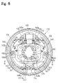
- a plan view of a rear drum brake device comprising a parking brake is illustrated.
- the structure of the drum brake device is such that the right half and the left half of the drum brake device in the drawings are symmetrically structured except for the parking brake and the screws of the shoe clearance adjustment devices 30 being formed inversely, the following explanation relates only to the structure of the left half of the drawing, whereas the explanation of the structure of the right half is omitted because the features and details are marked with the same reference numerals as in the left half.
- drum brake device set is by no means limited to what is described with reference to the drawings.
- a wheel cylinder 20 serving as a service brake actuator is mounted on the upper portion of a back plate 10, and a shoe clearance adjustment device 30, also functioning as a first anchor, utilizing an anchor body 22 integrally formed with a cylinder body 21, is arranged at the inner side of the brake drum connected adjacent to the wheel cylinder 20.
- a second anchor 11 is mounted on the lower portion of the back plate 10.
- a brake shoe 40 is structured such that a shoe rim 41 and a shoe web 42 are connected to form a T-shape element in cross-section, and a lining 43 is fixed on the periphery of the shoe rim 41.
- the one end or upper end 40a of the brake shoe 40 engages with an adjustment bolt 31 functioning as a male-female screw member of the shoe clearance adjustment device 30.
- the other end or lower end 40b abuts against and engages with the side end surface of a flat anchor plate 12a constituting the second anchor 11.
- This embodiment comprises a structure where the lower end 40b of the brake shoe 40 is supported as a floating anchor.
- An arc-shaped pivot lever 50 is superimposed on the shoe web 42 and is provided between the wheel cylinder 20 and the second anchor 11.
- the one end or upper end 50a of the pivot lever 50 functionally engages with a piston 23 of the wheel cylinder 20.
- the other end or lower end 50b abuts against and engages with the side flat end surface of an anchor plate 12b constituting the second anchor 11.
- the upper middle portion 50c adjacent to the upper end 50a engages with the adjustment bolt 31 of the shoe clearance adjustment device 30.
- Fig. 3 shows a cross-section view of the pivotal part of the brake shoe 40 and the pivot lever 50 at the left half of the drum brake device.
- a hollow protuberance 50d is projecting toward the shoe web 42 on the central region of the pivot lever 50.
- the protuberance 50d is inserted through and is rotatably pivoted in a circular hole 42a formed in the shoe web 42.
- a circular hole may be formed at the pivot lever 50 side and a protuberance may be formed at the shoe web 42 side.
- a pin may be used to substitute for the protuberance.
- a pivotal part of the brake shoe 40 and the pivot lever 50 are supported by a shoe hold pin 61 which is inserted through an opening inside of the protuberance 50d.
- the one end of the pin 61 is vertically and swingably set on the back plate 10.
- a plate spring 62 is temporarily fixed by the other end of the pin 61 and is compressed and installed on the pivot lever 50.
- the brake shoe 40 is elastically held on the back plate 10, and the pivot lever 50 is held on the shoe web 42.
- a bolt may be used instead of the shoe hold pin 61.
- the one end of such a bolt would be fixed on the back plate 10, and upper and lower nuts fastened on the other end would movably hold the brake shoe 40 and the pivot lever 50.
- Fig. 4 illustrates an enlarged cross-section view of the left half of the shoe clearance adjustment device 30.
- a penetrating hole 22a is formed in an anchor body 22.
- the male screw of the adjustment bolt 31 is rotatably fitted in the hole 22a.
- a notched groove 31a with a step is formed at the left side of the adjustement bolt 31.
- the upper end of the shoe web 42 i.e. the upper end 40a of the brake shoe 40, abuts against the bottom of the groove 31a.
- the upper middle portion 50c of the pivot lever 50 engages with the groove 31a with a slight clearance between the pivot lever 50 and the bottom of the groove 31a.
- a toothed adjustment wheel 32 is screwed onto the axle portion of the male screw of the adjustment bolt 31.
- a number of small teeth are formed on the circumferential surface of the adjustment wheel 32. Moving back of the adjustment bolt 31 relative to the anchor body 22 is restricted by abutting a right side surface of the adjustment wheel 32 against the left surface of the anchor body 22. By controlling the rotation of the adjustment wheel 32, the amount of protrusion of the adjustment bolt 31 relative to the anchor body 22 may be changed.
- the shoe clearance adjustment device 30 comprises the adjustment bolt 31 fitted in the anchor body 22 and the adjustment wheel 32 screwed onto the adjustment bolt 31.
- the clearance may be manually adjusted by inserting a screw driver or the like from the outside of the brake after removing a plug 15 in the back plate 10. Then, the adjustment wheel 32 is manually rotated, and the adjustment bolt 31 is screwed out from or into the wheel 32.
- An automatic shoe clearance adjustment device comprises an adjustment lever 33 and an adjustment spring 34 in addition to the structure of the shoe clearance adjustment device 30.
- FIG. 5 A plan view of the adjustment lever 33 is illustrated in Fig. 5 of the drawings.
- the adjustment lever 33 as a whole is an almost Y-shaped flat plate.
- a pin hole 33b is formed in the one branching arm, namely the first arm 33a, and the end of the other branching arm, namely the second arm 33c, is bent out approximately at a right angle.
- a hole or slit is formed in the bent end of the non-branching arm, namely a third arm 33d, to temporarily set the one hook of the adjustment spring 34. Furthermore, an edge at the joint section of the first and second arms 33a and 33c is bent at a right angle to form an abutting part 33e.
- the adjustment lever 33 is designed such that the pin hole 33b of the first arm 33a is pivotally supported by a pin 35 fixed on the pivot lever 50.
- the adjustment spring 34 is stretched between the third arm 33d of the adjustment lever 33 and the pivot lever 50. A rotation force in the counterclockwise direction is constantly applied to the adjustment lever 33 with the pin 35 as the fulcrum.
- the abutting part 33e abuts against and engages with the stepped surface 31b of the notched groove 31a of the adjustment bolt 31 due to a spring force exerted by the spring 34 in the compressing direction.
- the second arm 33c engages with the adjustment wheel 32, see Fig. 4.
- one shoe return spring 16 is stretching between the pair of brake shoes 40 adjacent to the wheel cylinder 20
- another shoe return spring 17 is stretching between the pair of brake shoes 40 adjacent to the second anchor 11.
- the moment about the pivot point of the brake shoes 40 on the pivot levers 50 operating on the brake shoes 40 by the one shoe return spring 16 and the other shoe return spring 17 is designed to be larger at the lower ends 40b side than at the upper ends 40a side.
- a strut 70 engages with the pivot lever 50 at the left side of the drawing, and at the same time, the right end of the strut 70 is rotatably supported at a mid-portion 71a of an L-shaped brake lever 71 with a pin 72 as the fulcrum.
- a notched groove for connecting the inner cable of the parking brake cable is formed at an outer end 71b of the brake lever 71 freely installed through the back plate 10.
- An inner end 71c of the brake lever 71 engages with the pivot lever 50 as shown at the right side of the drawing.
- a lever stopper 18 restricts a returning position of the brake lever 71.
- a bracket 19 fixes an outer casing of a parking brake cable.
- a return spring 73 is stretched between the brake lever 71 and the lever stopper 18.
- the pivot lever 50 When the piston 23 of the wheel cylinder 20 presses the upper end 50a of the pivot lever 50, the pivot lever 50 opens with the point of abutment of the lower end 50b of the pivot lever 50 against the second anchor 11.
- the opening force of the pivot lever 50 is transmitted to the brake shoe 40 via the protuberance 50d, and the brake shoe 40 frictionally engages with the brake drum 80 (shown in Fig. 2), where the lining 43 is frictionally engaging in order to generate a braking force.
- the upper end 40a of the brake shoe 40 at the right side of the drawing is supported by the adjustment bolt 31 of the shoe clearance adjustment device 40 at the right side of the drawing to function as a leading shoe with a self-servo property. Accordingly, a pair of right and left brake shoes 40 generates a braking force which is the same as the two-leading type.
- the lower end 40b of the brake shoe 40 at the right side of the drawing is supported by the second anchor 11 to function as a leading shoe with a self-servo property.
- the upper end 40a of the brake shoe 40 at the left side of the drawing is supported by the adjustment bolt 31 of the shoe clearance adjustment device 30 at the left side of the drawing to function as a leading shoe with a self-servo property. Consequently, the pair of right and left brake shoes 40 generates a braking force of the two-leading type in the same manner as above.
- the brake shoes provide a stable braking force of a dual-two leading type (D2L-type) functioning as a leading shoe with a self-servo property.
- D2L-type dual-two leading type
- the upper end 50a of the pivot lever 50 is pressed to open with the point of the abutment of the second anchor 11 as the fulcrum, and the upper end 40a of the brake shoe 40 opens via the pivotal part.
- the amount of opening of the pivot lever 50 will increase due to the fact that the lining 43 is worn out. If the amount of rotation of the second arm 33c constituting the adjustment lever 33 exceeds the pitch of the adjustment wheel 32, the adjustment wheel 32 is rotated to project the adjustment bolt 31 further from the anchor body 22, thereby automatically adjusting the clearance between the brake drum 80 and the lining 43 to be constant.
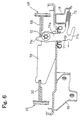
- a parking brake operation as shown in Figs. 1 and 6 of the drawings, if the outer end portion 71b of the brake lever 71, exposed to the outside of the back plate 10, is pulled in the direction of the arrow (see Fig. 6), the portion 71b rotates in the clockwise direction with the pivot point (pin 72), with the strut 70 as the fulcrum.
- the inner end portion 71c moves the lower end 50b of the pivot lever 50 at the right side of the drawing to the right.
- the pivot lever 50 opens with the point of abutment with the adjustment bolt 31 at the right side of the drawing as the fulcrum, thereby opening the brake shoe 40 at the right side of the drawing via the protuberance 50d and similarly opening the pivot lever 50 and the brake shoe 40 pivotally supported on the pivot lever 50 at the left side of the drawing via the strut 70.
- the pulling direction of the brake lever 71 is not limited to the type where the brake lever 71 is to be pulled toward the front side of the vehicle as in the embodiment described above. Rather, the parking brake lever may be of the type where the outer end 71b of the almost J-shaped brake lever 71 is to be pulled in the right angle direction or vehicle axle direction relative to the back plate 10, see Fig. 7 of the drawings.
- a second anchor 111 at the lower end 150b of a pivot lever 150 is to be of a pivot shape
- Figs. 8 to 10 illustrate another embodiment of movably pivoting a brake shoe 140 in the circumferential direction of the brake drum relative to the pivot lever 150.
- Two anchor plates 112a and 112b are superimposed on a protrusion of a back plate 110.
- a retaining plate 113 is superimposed on the anchor plates 112a and 112b.
- the anchor plates 112a and 112b and the retaining plate 113 are integrally fixed on the back plate 110 by means of rivets 114. Otherwise, the structure of this embodiment is the same as the first embodiment.
- the side end surface of the anchor plate 112a supporting a lower end 140b of a shoe web 142 (a lower end 140b of the brake shoe 140) is a flat surface to support the lower end 140b as a floating anchor.
- the side end surface of the anchor plate 112b supporting the lower end 150b of the pivot lever 150 is an arc-shaped surface (pivot) to support the end 150b as a pivot anchor.
- the side end surface of the anchor plate 112b is designed as an arc-shaped surface so that the lower end 150b of the pivot lever 150 is rotatable but not vertically slidable, as shown in the drawing.
- the two anchor plates 112a and 112b can each easily be punched by means of a press.
- the lower end 150b of the pivot lever 150 is designed to be convex, and the side end surface of the anchor plate 112b is designed as a concave arc-shaped surface; however, the convex and concave portions may be exchanged with each other.
- the central region of the pivot lever 150 and the brake shoe 140 are pivotally supported so as to be movable in the circumferential direction of the brake drum.
- a hollow protuberance 150d integrally formed at the central region of the pivot lever 150 is freely fitted within a long hole 142b formed in the shoe web 142 which extends in the circumferential direction of the brake drum.
- the long hole 142b is designed with an arc shape having the brake center as a center point of a radius. This is to enable a relative movement in the circumferential direction of the brake drum between the long hole 142b and the protuberance 150d fitting with the long hole 142b.
- the long hole 142b is at least designed in such a manner that a force transmitting surface 142c of the outer side of the brake is fitted with a circular arc 142d with respect to a line to the brake center as a radius. There is no requirement for the shape of the surface facing the force transmitting surface 142c of the long hole 142b.
- the brake shoe 140 at the left side when in braking operation is explained next.
- the brake shoe 140 opens and begins to operate the rotation force of the brake drum, since the protuberance 150d is to make a relative movement corresponding to the force transmitting surface 142c of the long hole 142b, the brake shoe 140 singularly moves smoothly relative to the pivot lever 150 and functions as a leading shoe with a self-servo property, even if the brake drum is rotating in the clockwise direction, namely by supporting the upper end 140a of the brake shoe 140 at the adjustment bolt 131 of the shoe clearance adjustment device 130.
- an operation force of the wheel cylinder 120 relative to the rotational force of the brake drum operates in the opposite direction; however, the lower end 150b of the pivot lever 150 is unmovably supported by the anchor plate 112b, and the brake shoe 140 singularly moves in the circumferential direction which maintains the braking effectiveness.
- the anchor plate 112b at the lower end 150b of the pivot lever 150 is provided with a pivot shape, and the brake shoe 140 is movable in the circumferential direction of the brake drum so that an operation force of the service brake does not affect the braking effectiveness as a loss.
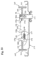
- Fig. 11 shows an example of a strut 270 with an automatic stroke adjustment mechanism, wherein a pivot lever 250 at the right side is fitted in a groove 270a of the left end of the strut 270, and an inner end 271c of a brake lever 271 protrudes through and engages with a rectangular hole 250e formed in the pivot lever 250.
- a spring force of a spring 274 stretching between the strut 270 and the pivot lever 250 on the right side is applied in a direction to maintain the fitting.
- a bell crank lever 275 is rotatably supported with a pin 276 as the fulcrum and movable along the plate surface in the longitudinal direction of the strut 270.
- a spring 277 is stretching between the strut 270 and a pin 276, and applies a spring force in a direction to maintain the engagement between the teeth 270b and 275b.
- a cam arm 275a at the left side of the bell crank lever 275 is freely fitted with a rectangular hole 250e formed in the pivot lever 250 at the left side of the drawing.
- the mounting load of both springs 274 and 277 is designed so that the load of the spring 274 at the right side of the drawing is greater than that of the spring 277 at the left side of the drawing.
- the present invention provides various advantageous effects which are summarized as follows:
- an adjustment spring force may be smaller and nevertheless a stable shoe clearance is maintained.
- An automatic shoe cleareance adjustment of a pair of brake shoes is conducted in the same direction of the brake drum rotation, thereby providing a stable clearance between the brake drum and each brake shoe. Accordingly, there is no need to be concerned with a quick lining wear as a result of one brake shoe load becoming greater.
- a pair of pivot levers is each supported by a pivot anchor.
- Each brake shoe is pivotally supported on the corresponding pivot lever so as to be movable in the circumferential direction of the brake drum relative to each pivot lever. Therefore, the operation force of the service brake does not affect the braking effectiveness as a loss.
- An anchor body is formed at one portion of the service brake actuator, and the anchor body is effectively utilized as a component of the shoe clearance adjustment device.
- the other anchor supporting each lower end of the brake shoe and pivot lever may be formed by superimposing two anchor plates which may be formed by means of a press. This is an easy processing, and the degree of design freedom for the outer shape is much greater.
- drum brake device as described above has the advantage of wide commercial utility. It should be understood that the specific form of the invention described above is intended to be representative only, as certain modifications within the scope of these teachings will be readily apparent to those skilled in the art.
Landscapes
- Engineering & Computer Science (AREA)
- General Engineering & Computer Science (AREA)
- Mechanical Engineering (AREA)
- Braking Arrangements (AREA)
Applications Claiming Priority (2)
| Application Number | Priority Date | Filing Date | Title |
|---|---|---|---|
| JP26636098 | 1998-09-21 | ||
| JP10266360A JP2000097268A (ja) | 1998-09-21 | 1998-09-21 | ドラムブレーキ装置 |
Publications (2)
| Publication Number | Publication Date |
|---|---|
| EP0989322A2 true EP0989322A2 (de) | 2000-03-29 |
| EP0989322A3 EP0989322A3 (de) | 2002-02-27 |
Family
ID=17429871
Family Applications (1)
| Application Number | Title | Priority Date | Filing Date |
|---|---|---|---|
| EP99118610A Withdrawn EP0989322A3 (de) | 1998-09-21 | 1999-09-21 | Trommelbremsvorrichtung |
Country Status (2)
| Country | Link |
|---|---|
| EP (1) | EP0989322A3 (de) |
| JP (1) | JP2000097268A (de) |
Cited By (3)
| Publication number | Priority date | Publication date | Assignee | Title |
|---|---|---|---|---|
| EP1116896A3 (de) * | 2000-01-11 | 2002-10-30 | Nisshinbo Industries Inc. | Trommelbremseeinheit |
| CN113217568A (zh) * | 2021-06-07 | 2021-08-06 | 河北百龙汽车配件股份有限公司 | 一种双制动分泵刹车蹄 |
| US20210254678A1 (en) * | 2020-02-17 | 2021-08-19 | Hyundai Mobis Co., Ltd. | Drum brake apparatus |
Families Citing this family (1)
| Publication number | Priority date | Publication date | Assignee | Title |
|---|---|---|---|---|
| US20030089561A1 (en) * | 2001-11-13 | 2003-05-15 | Manuel Barbosa | Dual leading-shoe drum brake |
Citations (1)
| Publication number | Priority date | Publication date | Assignee | Title |
|---|---|---|---|---|
| JPH1047396A (ja) | 1996-08-02 | 1998-02-17 | Nisshinbo Ind Inc | ドラムブレーキ装置 |
Family Cites Families (4)
| Publication number | Priority date | Publication date | Assignee | Title |
|---|---|---|---|---|
| US2389618A (en) * | 1942-08-01 | 1945-11-27 | Bendix Aviat Corp | Brake |
| US3326331A (en) * | 1965-01-27 | 1967-06-20 | Wagner Electric Corp | Automatic adjustor mechanism |
| DE3112550A1 (de) * | 1981-03-30 | 1982-11-04 | Deutsche Perrot-Bremse Gmbh, 6800 Mannheim | Nachstell- und zentriervorrichtung am durchschiebeschloss einer innenbacken-servobremse |
| JP3338946B2 (ja) * | 1996-10-08 | 2002-10-28 | 日清紡績株式会社 | ドラムブレーキ装置 |
-
1998
- 1998-09-21 JP JP10266360A patent/JP2000097268A/ja active Pending
-
1999
- 1999-09-21 EP EP99118610A patent/EP0989322A3/de not_active Withdrawn
Patent Citations (1)
| Publication number | Priority date | Publication date | Assignee | Title |
|---|---|---|---|---|
| JPH1047396A (ja) | 1996-08-02 | 1998-02-17 | Nisshinbo Ind Inc | ドラムブレーキ装置 |
Cited By (4)
| Publication number | Priority date | Publication date | Assignee | Title |
|---|---|---|---|---|
| EP1116896A3 (de) * | 2000-01-11 | 2002-10-30 | Nisshinbo Industries Inc. | Trommelbremseeinheit |
| US20210254678A1 (en) * | 2020-02-17 | 2021-08-19 | Hyundai Mobis Co., Ltd. | Drum brake apparatus |
| US11788589B2 (en) * | 2020-02-17 | 2023-10-17 | Hyundai Mobis Co., Ltd. | Drum brake apparatus |
| CN113217568A (zh) * | 2021-06-07 | 2021-08-06 | 河北百龙汽车配件股份有限公司 | 一种双制动分泵刹车蹄 |
Also Published As
| Publication number | Publication date |
|---|---|
| EP0989322A3 (de) | 2002-02-27 |
| JP2000097268A (ja) | 2000-04-04 |
Similar Documents
| Publication | Publication Date | Title |
|---|---|---|
| EP2878850B1 (de) | Trommelbremsenvorrichtung | |
| US6394237B1 (en) | Automatic shoe clearance adjustment device for a drum brake | |
| EP0989322A2 (de) | Trommelbremsvorrichtung | |
| EP0908641A1 (de) | Trommelbremseinrichtung | |
| US6523652B2 (en) | Drum brake device | |
| US6065571A (en) | Drum brake system and device | |
| US6302245B1 (en) | Drum brake device | |
| JP3338949B2 (ja) | ドラムブレーキ装置 | |
| EP1350978B1 (de) | Trommelbremse mit zwei unterschiedlichen Betätigungsvorrichtung | |
| JP4672130B2 (ja) | シュー間隙自動調節機構付きドラムブレーキ | |
| JPH1047396A (ja) | ドラムブレーキ装置 | |
| US6435322B1 (en) | Duo two leading type drum brake device | |
| JP2628791B2 (ja) | 自動調節装置を備えた機械作動形ブレーキ | |
| US8490759B2 (en) | Drum brakes | |
| EP0905401A2 (de) | Trommelbremse | |
| JPS6325394Y2 (de) | ||
| JP3867005B2 (ja) | ドラムブレーキ装置 | |
| JPS643857Y2 (de) | ||
| JP3554949B2 (ja) | ドラムブレーキ装置 | |
| JP3772387B2 (ja) | パーキングブレーキ装置 | |
| JPS6325393Y2 (de) | ||
| JPH051731A (ja) | ドラムブレーキ装置 | |
| JPS5814254Y2 (ja) | ドラムブレ−キ装置の自動間隙調整装置 | |
| JPH0727152A (ja) | カム作動式デュオサーボドラムブレーキ装置 | |
| JPS6135795Y2 (de) |
Legal Events
| Date | Code | Title | Description |
|---|---|---|---|
| PUAI | Public reference made under article 153(3) epc to a published international application that has entered the european phase |
Free format text: ORIGINAL CODE: 0009012 |
|
| AK | Designated contracting states |
Kind code of ref document: A2 Designated state(s): AT BE CH CY DE DK ES FI FR GB GR IE IT LI LU MC NL PT SE |
|
| AX | Request for extension of the european patent |
Free format text: AL;LT;LV;MK;RO;SI |
|
| PUAL | Search report despatched |
Free format text: ORIGINAL CODE: 0009013 |
|
| AK | Designated contracting states |
Kind code of ref document: A3 Designated state(s): AT BE CH CY DE DK ES FI FR GB GR IE IT LI LU MC NL PT SE |
|
| AX | Request for extension of the european patent |
Free format text: AL;LT;LV;MK;RO;SI |
|
| AKX | Designation fees paid | ||
| REG | Reference to a national code |
Ref country code: DE Ref legal event code: 8566 |
|
| STAA | Information on the status of an ep patent application or granted ep patent |
Free format text: STATUS: THE APPLICATION IS DEEMED TO BE WITHDRAWN |
|
| 18D | Application deemed to be withdrawn |
Effective date: 20020827 |