EP0989734A2 - Appareil pour guider des tuyaux et câbles dans un système d'imagerie - Google Patents
Appareil pour guider des tuyaux et câbles dans un système d'imagerie Download PDFInfo
- Publication number
- EP0989734A2 EP0989734A2 EP99203055A EP99203055A EP0989734A2 EP 0989734 A2 EP0989734 A2 EP 0989734A2 EP 99203055 A EP99203055 A EP 99203055A EP 99203055 A EP99203055 A EP 99203055A EP 0989734 A2 EP0989734 A2 EP 0989734A2
- Authority
- EP
- European Patent Office
- Prior art keywords
- hose
- optical carriage
- imaging system
- tray
- support bracket
- Prior art date
- Legal status (The legal status is an assumption and is not a legal conclusion. Google has not performed a legal analysis and makes no representation as to the accuracy of the status listed.)
- Withdrawn
Links
Images


Classifications
-
- H—ELECTRICITY
- H04—ELECTRIC COMMUNICATION TECHNIQUE
- H04N—PICTORIAL COMMUNICATION, e.g. TELEVISION
- H04N1/00—Scanning, transmission or reproduction of documents or the like, e.g. facsimile transmission; Details thereof
- H04N1/00519—Constructional details not otherwise provided for, e.g. housings, covers
- H04N1/00549—Counter-measures for mechanical vibration not otherwise provided for
-
- H—ELECTRICITY
- H04—ELECTRIC COMMUNICATION TECHNIQUE
- H04N—PICTORIAL COMMUNICATION, e.g. TELEVISION
- H04N1/00—Scanning, transmission or reproduction of documents or the like, e.g. facsimile transmission; Details thereof
- H04N1/00519—Constructional details not otherwise provided for, e.g. housings, covers
-
- H—ELECTRICITY
- H04—ELECTRIC COMMUNICATION TECHNIQUE
- H04N—PICTORIAL COMMUNICATION, e.g. TELEVISION
- H04N1/00—Scanning, transmission or reproduction of documents or the like, e.g. facsimile transmission; Details thereof
- H04N1/00976—Arrangements for regulating environment, e.g. removing static electricity
-
- H—ELECTRICITY
- H04—ELECTRIC COMMUNICATION TECHNIQUE
- H04N—PICTORIAL COMMUNICATION, e.g. TELEVISION
- H04N1/00—Scanning, transmission or reproduction of documents or the like, e.g. facsimile transmission; Details thereof
- H04N1/04—Scanning arrangements, i.e. arrangements for the displacement of active reading or reproducing elements relative to the original or reproducing medium, or vice versa
- H04N1/06—Scanning arrangements, i.e. arrangements for the displacement of active reading or reproducing elements relative to the original or reproducing medium, or vice versa using cylindrical picture-bearing surfaces, i.e. scanning a main-scanning line substantially perpendicular to the axis and lying in a curved cylindrical surface
- H04N1/0607—Scanning a concave surface, e.g. with internal drum type scanners
-
- H—ELECTRICITY
- H04—ELECTRIC COMMUNICATION TECHNIQUE
- H04N—PICTORIAL COMMUNICATION, e.g. TELEVISION
- H04N1/00—Scanning, transmission or reproduction of documents or the like, e.g. facsimile transmission; Details thereof
- H04N1/04—Scanning arrangements, i.e. arrangements for the displacement of active reading or reproducing elements relative to the original or reproducing medium, or vice versa
- H04N1/06—Scanning arrangements, i.e. arrangements for the displacement of active reading or reproducing elements relative to the original or reproducing medium, or vice versa using cylindrical picture-bearing surfaces, i.e. scanning a main-scanning line substantially perpendicular to the axis and lying in a curved cylindrical surface
- H04N1/0671—Scanning arrangements, i.e. arrangements for the displacement of active reading or reproducing elements relative to the original or reproducing medium, or vice versa using cylindrical picture-bearing surfaces, i.e. scanning a main-scanning line substantially perpendicular to the axis and lying in a curved cylindrical surface with sub-scanning by translational movement of the main-scanning components
Definitions
- the present invention is in the field of imaging systems. More particularly, the present invention provides an apparatus for routing and flexing coolant hoses and an electrical cable to a laser system mounted on a movable optical carriage in an imaging system without introducing mechanical disturbances to the optical carriage.
- an optical carriage is used to displace a laser system or other imaging source in a slow scan direction along an internal drum to expose a supply of media supported on the drum.
- the specific type of laser system employed by an imaging system depends in part on the exposure requirements of the media. For example, when using aluminum plates having a light sensitive surface emulsion, a lower power laser system, such as a doubled frequency Nd (neodymium):YAG (yttruim, aluminum, garnet) laser, may be used. However, when using thermal plates, a higher power laser system is generally required. Unfortunately, such higher power laser systems commonly require a complex cooling system wherein a liquid or gaseous coolant is cycled through the laser system to prevent the laser system from overheating. Additionally, an additional source of power is often required due to the increased power consumption of many high power laser systems.
- the coolant hoses for supplying coolant to the laser system can adversely affect image quality by imparting mechanical disturbances to the optical carriage as the optical carriage is displaced along the internal drum of the imaging system. Further, the coolant hoses may kink during displacement of the optical carriage, causing a blockage of the coolant to the laser system. This may result in the overheating and damage of the laser system.
- the electrical cable supplying power to the laser system may also disturb the optical carriage during imaging.
- the present invention provides a hose and cable routing system for routing and flexing coolant supply and return hoses between a refrigeration system and the optical carriage of an imaging system, and for routing and flexing an electrical cable between a power source and the optical carriage, without introducing mechanical disturbances to the optical carriage.
- the hose and cable routing system includes a support tray, mounted to the imaging system, for supporting the coolant hoses and electrical cable, and a movable support bracket for supporting and running the coolant hoses and electrical cable from the support tray to the optical carriage.
- a track is provided to guide the movable support bracket along the imaging system in response to a displacement of the optical carriage or a drive system.
- a vibration isolator formed of a material capable of dampening vibrations and other mechanical disturbances, is preferably mounted between the support bracket and the optical carriage.
- a second embodiment of the present invention provides a self coiling, retracting, hose and cable support system for supporting the coolant hoses and electrical cable adjacent the optical carriage.
- the hose and cable support system includes a concave, flexible tray and a system for extending or retracting the tray in response or in conjunction with a displacement of the optical carriage.
- a further embodiment of the present invention provides a hose and cable support system including a coiled, nestable hose assembly for supplying coolant and power to the optical carriage.
- An upper portion of each coil of the hose assembly is movably supported to a rail by a linear bearing, thereby allowing the hose assembly to expand and contract without kinking in response to a displacement of the optical carriage.
- FIG. 1 An example of an internal drum imaging system, generally designated as 10, is illustrated in FIG. 1.
- the imaging system 10 is a computer to plate imaging system, commonly referred to as a platesetter, wherein digital data is imaged directly onto a printing plate.
- the hose and cable routing system of the present invention may also be used in other types of internal drum imaging systems, including imagesetters, digital proofers, and the like, without departing from the intended scope of the present invention.
- the imaging system 10 generally includes a front end server or computer 12 for outputting a print job, a raster image processor (RIP) 14 for translating the data corresponding to the print job into a pattern of dots, and a platesetter 16 for imaging the dots onto a printing plate.
- the platesetter 16 has three major components, including an internal drum imaging engine 18, an on-line plate handler 20, and an on-line plate processor/stacker 22.
- the plate handler 20 includes at least one cassette 24 containing a supply of printing plates 26 which are generally formed from aluminum, polyester, or other suitable materials.
- a plate shuttle mechanism or "picker” 29 removes a single plate 26 from one of the cassettes 24 and transports the plate 26 to the imaging engine 18.
- the imaging engine 18 includes an internal drum 28 having a cylindrical imaging surface 30 for supporting a plate 26 during imaging.
- An applicator assembly 32 is used to position and iron the plate 26 against the imaging surface 30 of the internal drum 28. Once properly positioned by the applicator assembly 32 against the imaging surface 30, the plate 26 is exposed by an imaging beam 34 radiating from a laser system 36 carried by a movable optical carriage 38.
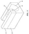
- FIG. 2 there is illustrated a perspective view of the optical carriage 38 supported on an upper structure 40 of the internal drum 28.
- the upper structure 40 includes a rail 42 for movably supporting the optical carriage 38 parallel to the longitudinal axis of the internal drum 28. Additional support structure (not shown) may be used to support/guide the optical carriage 38 relative to the internal drum 28.
- the optical carriage 38 is self-propelled and includes an on-board motor (not shown) for displacing the optical carriage 38 along the internal drum 28.
- external drive means may be used to displace the optical carriage 38.
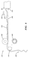
- a hose and cable routing system 50 in accordance with a first preferred embodiment of the present invention is illustrated in FIG. 3.
- the hose and cable routing system 50 is provided to route and flex a coolant supply hose 52 and a coolant return hose 54 between a refrigeration system 56, external to the internal drum imaging engine 18 (FIG. 1), and the laser system 36 mounted on the movable optical carriage 38, without introducing deleterious mechanical disturbances to the optical carriage 38.
- the coolant supply hose 52 is used to supply a liquid or gaseous coolant from the refrigeration system 56 to the laser system 36.
- the return coolant hose 54 is used to direct and recirculate the coolant warmed by the laser system 36 through the refrigeration system 56 for cooling.
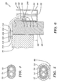
- the coolant supply and return hoses 52, 54 may be separately coupled between the refrigeration system 56 and the laser system 36, may be attached together along their length, or may be enclosed together within a flexible conduit 58 as illustrated in FIG. 4.
- an electrical cable 60 for supplying power to the laser system 36 may be piggybacked on the flexible conduit 58.
- a layer of insulation 59 is preferably provided over the coolant supply and return hoses 52, 54 along their length to prevent condensation on the exterior of the hoses 52, 54.
- the layer of insulation 59 is then covered by the flexible conduit 58 to protect the insulation 59 from damage.
- the electrical cable 60 may be attached to one or both of the coolant supply and return hoses 52, 54.
- the hose and cable routing system 50 includes a support tray 62 mounted to the frame (not shown) of the internal drum 28.
- the support tray 62 may be mounted to the frame using any suitable hardware.
- the support tray 62 comprises a first side 64 mounted to the frame, a second side 66 positioned away from and mounted to the first side 64 by a bottom section 68, and first and second open ends 70, 72.
- the coolant supply and return hoses 52, 54 extend out from the first open end 70 of the support tray 62 to the refrigeration system 56.
- the hose and cable routing system 50 further includes a movable support bracket 76 for supporting and running the coolant supply and return hoses 52, 54 over the upper structure 40 to the optical carriage 38 in a direction perpendicular to the direction of motion of the optical carriage 38.
- a cover assembly 78 is used to secure the coolant supply and return hoses 52, 54 to the support bracket 76.
- the support bracket 76 includes an outwardly flanged bottom section 80. The distance between the outwardly flanged bottom section 80 of the support bracket 76 and the bottom section 68 of the support tray 62 defines the radius of curvature of bend area 82 of the coolant supply and return hoses 52, 54.
- the support bracket 76 is preferably formed of metal or other rigid material. However, the support bracket 76 may be formed of plastic, hard rubber or other suitable material having sufficient strength to support the coolant supply and return hoses 52, 54.
- a track 84 is provided to guide the support bracket 76 along the upper structure 40 of the internal drum 28 as the optical carriage 38 is displaced along the internal drum 28.
- the track 84 is attached to the first side 64 of the support tray 62.
- a wheel assembly 86 (FIG. 6) mounted to the underside of the flanged bottom section 80 of the support bracket 76 includes a wheel 88 that is received within the track 84.
- the wheel 88 is configured to roll along the track 84 as the optical carriage 38 and the support bracket 76 are displaced along the internal drum 28.
- the attached coolant supply and return hoses 52, 54 are lifted off or laid down on the bottom section 68 of the support tray 62 without kinking and without imparting mechanical disturbances to the optical carriage 38.
- the track 84 is aligned parallel to the rail 42 which movably supports the optical carriage 38.
- An additional support bracket 170 may be mounted to an interior surface of first side 64 of the support tray 62 to reduce mechanical disturbances caused by the displacement of the coolant supply and return hoses 52, 54.
- the support bracket 170 prevents the coolant supply and return hoses 52, 54 (and electrical cable 60, if present) from buckling in response to a displacement of the support bracket 76 toward the bend area 82 of the hoses.
- the coolant supply and return hoses 52, 54 are prevented from buckling (as shown in phantom) within the support tray 62 by the support bracket 170 as the support bracket 76 is displaced in the direction indicated by directional arrow 172.
- an active drive system may be utilized.
- a motor/cable drive system may be used to displace the support bracket 76 and attached coolant supply and return hoses 52, 54 along the length of the internal drum 28.
- Such a motor/cable drive system may include a cable 92, a pulley 94, and a motor 96 for driving the cable 92 around the pulley 94.
- the cable 92 is attached to the wheel assembly 86 (FIG. 6) or the support bracket 76 such that a displacement of the cable 92 results in a corresponding displacement of the support bracket 76 and attached coolant supply and return hoses 52, 54.
- a position feedback controller may be used to ensure that the displacement of the support bracket 76 does not lead or lag the optical carriage 38 by more than a predetermined amount.
- FIG. 6 A partial cross-sectional view of the hose and cable routing system 50 of FIG. 3 is illustrated in FIG. 6.
- the cover assembly 78 is not shown for clarity.
- the wheel assembly 86 is mounted to the underside of the flanged bottom section 80 of the support bracket 76 and includes the wheel 88 that is received within the track 84.
- the wheel assembly 86 additionally includes an axle 98 for rotatably supporting the wheel 88, and an axle support 100 mounted to the flanged bottom section 80 of the support bracket 76.
- the support bracket 76 may be directly fixed to the optical carriage 38, or may be coupled to the optical carriage 38 using a vibration isolator 102.
- the vibration isolator 102 is preferably formed of rubber. However, other materials capable of dampening vibrations or other mechanical disturbances generated by the hose and cable routing system 50, the coolant supply and return hoses 52, 54, or other sources, may be used without departing from the scope of the present invention.
- the vibration isolator 102 is mounted between the support bracket 76 and a mounting assembly 104 fixed to the optical carriage 38. As illustrated in FIGS. 6 and 7, one end of the support bracket 76 includes a plurality of mounting posts 106. Similarly, the mounting assembly 104 includes a plurality of mounting posts 108. The mounting posts 106, 108 are inserted into corresponding mounting holes 110 formed on the vibration isolator 102. Securing hardware (not shown) may be positioned on each of the mounting posts 106, 108 to prevent the vibration isolator from dislodging. Other known hardware may alternately be used to join the vibration isolator 102 between the support bracket 76 and the mounting assembly 104.
- FIGS. 8 and 9 A self coiling, retracting, hose and cable support system 120 in accordance with an alternate embodiment of the present invention is illustrated in FIGS. 8 and 9.
- the hose and cable support system 120 includes a concave flexible tray 122 for supporting coolant supply and return hoses and/or power cables, illustrated for clarity as a single hose 124 in FIGS. 8 and 9, as the optical carriage 38 is displaced along the internal drum 28 of the imaging system.
- the tray 122 extends substantially horizontally away from the optical carriage 38.
- the hose and cable support system 120 further includes a spool roller 126 for keeping the hose 124 on the tray 122, a driven roller 128 for winding or unrolling the tray 122, and an idle roller 130 for tensioning the tray 122 as the tray 122 is retracted or extended, and for guiding the hose 124 to a coiling location 132.
- a first end of the hose 124 is attached to the side or other suitable location on the optical carriage 38 using mounting hardware 134.
- the other end of the hose 124 is attached to a refrigeration/power system (not shown).
- the tray 122 supports the hose along a portion of its length. As the optical carriage 38 is displaced along the internal drum in the direction indicated by directional arrow 136, the tray 122 is retracted and coiled onto the driven roller 128. As shown, retraction of the hose 124 is effected by a clockwise rotation of the driven roller 128. As the tray 122 is retracted, portions of the hose 124 previously supported by the tray 122 pass over the idle roller 130 and descend toward the coiling location 132. In the coiling location, the hose 124 curls on itself without kinking. Sufficient slack is maintained in the hose 124 to prevent the hose 124 from disturbing the optical carriage 38 during imaging. Further, the rotation of the driven roller 128 may be controlled via a positional controller or the like according to the displacement of the optical carriage 38 to minimize mechanical disturbances imparted to the optical carriage 38 by the hose 124, tray 122, or other sources.
- the tray 122 is extended to support the hose 124 as the optical carriage 38 is displaced along the internal drum in a reverse direction as indicated by directional arrow 138. Extension of the tray 122 occurs in response to a counterclockwise rotation of the driven roller 128. As the tray 122 is extended and passes over the idle roller 130, the hose 124 is pulled onto and supported by the tray 122 without introducing mechanical disturbances to the optical carriage 38.
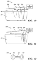
- FIGS. 10 and 11 Yet another embodiment of a hose and cable support system 150 in accordance with the present invention is illustrated in FIGS. 10 and 11.
- a coiled, nestable hose assembly 152 incorporating coolant supply and return hoses 154, 156 and a power cable 158 (see FIG. 12) is used to deliver coolant and power to a laser system on the movable optical carriage 38 with minimal disturbances to the optical carriage 38 during imaging.
- the hose assembly 152 includes a single hose that is preferably formed in a "dog-bone" shape, wherein the coolant supply hose 154 and coolant return hose 156 are joined and separated by the power cable 158.
- the hose assembly 152 is preferably formed in a coiled nested configuration such that when the hose assembly 152 is in a maximally compressed state, the overall width of the nested coil is approximately that of the single hose (FIG. 14).
- the hose assembly 152 is connected between the optical carriage 38 and a refrigeration system.
- the smaller diameter end of the hose assembly 152 is attached to the optical carriage 38.
- the larger diameter end of the hose assembly 152 is attached to the refrigeration system.
- the hose assembly 152 due to its nested, coiled configuration, is capable of extending (FIG. 10) or compressing (FIG. 11) in response to a displacement of the optical carriage 38.
- each coil 160 of the hose assembly 152 is movably supported to a rail 162 by a linear bearing 164 or other similar device.
- the linear bearings 164 allow the hose assembly 152 to expand and contract in response to a displacement of the optical carriage 38 without introducing mechanical disturbances to the optical carriage 38.
- the rail 162 may be tilted at an angle with respect to the optical carriage 38 to use gravity to negate the extra load of the hose assembly 152 on the imaging carriage 38, and to overcome the drag forces of the hose assembly 152 on the rail 162.
Landscapes
- Engineering & Computer Science (AREA)
- Multimedia (AREA)
- Signal Processing (AREA)
- Environmental & Geological Engineering (AREA)
- Exposure And Positioning Against Photoresist Photosensitive Materials (AREA)
- Electric Cable Arrangement Between Relatively Moving Parts (AREA)
- Lasers (AREA)
- Electrophotography Configuration And Component (AREA)
- Cooling Or The Like Of Electrical Apparatus (AREA)
Applications Claiming Priority (2)
| Application Number | Priority Date | Filing Date | Title |
|---|---|---|---|
| US09/157,850 US6501500B1 (en) | 1998-09-21 | 1998-09-21 | Apparatus for routing hoses and cables in an imaging system |
| US157850 | 1998-09-21 |
Publications (2)
| Publication Number | Publication Date |
|---|---|
| EP0989734A2 true EP0989734A2 (fr) | 2000-03-29 |
| EP0989734A3 EP0989734A3 (fr) | 2001-04-18 |
Family
ID=22565539
Family Applications (1)
| Application Number | Title | Priority Date | Filing Date |
|---|---|---|---|
| EP99203055A Withdrawn EP0989734A3 (fr) | 1998-09-21 | 1999-09-20 | Appareil pour guider des tuyaux et câbles dans un système d'imagerie |
Country Status (3)
| Country | Link |
|---|---|
| US (1) | US6501500B1 (fr) |
| EP (1) | EP0989734A3 (fr) |
| JP (1) | JP2000101274A (fr) |
Cited By (1)
| Publication number | Priority date | Publication date | Assignee | Title |
|---|---|---|---|---|
| EP1453295A3 (fr) * | 2003-02-28 | 2005-08-24 | Eastman Kodak Company | Système anti-vibrations pour tambour intérieur d'un scanner |
Families Citing this family (9)
| Publication number | Priority date | Publication date | Assignee | Title |
|---|---|---|---|---|
| US6903467B2 (en) * | 2003-01-08 | 2005-06-07 | Nikon Corporation | Tube carrier reaction apparatus |
| US7048828B2 (en) * | 2003-11-26 | 2006-05-23 | Metso Paper, Inc. | Crimper with crimping wheels mounted on linear bearings |
| JP4444686B2 (ja) * | 2004-02-19 | 2010-03-31 | パナソニック株式会社 | レーザ光出射方法とその装置 |
| JP5257753B2 (ja) * | 2008-04-28 | 2013-08-07 | 株式会社リコー | 画像形成装置 |
| JP5446608B2 (ja) * | 2009-08-28 | 2014-03-19 | 株式会社リコー | 冷却装置及び画像形成装置 |
| JP2011048259A (ja) * | 2009-08-28 | 2011-03-10 | Ricoh Co Ltd | 冷却装置及び画像形成装置 |
| US8412068B2 (en) * | 2009-08-28 | 2013-04-02 | Ricoh Company, Ltd. | Cooling device including a water-absorbing member and image forming device |
| JP5446607B2 (ja) * | 2009-08-28 | 2014-03-19 | 株式会社リコー | 冷却装置及び画像形成装置 |
| JP5605689B2 (ja) * | 2010-07-02 | 2014-10-15 | 株式会社リコー | クリーニング装置及び画像形成装置 |
Family Cites Families (12)
| Publication number | Priority date | Publication date | Assignee | Title |
|---|---|---|---|---|
| FR2230472A1 (en) | 1973-05-22 | 1974-12-20 | Stumpf Guenter | Cutting device for textile webs uses focussing device for laser - mounted on bi-directionally moveable carriage above web |
| NO144622C (no) * | 1979-12-13 | 1981-10-07 | Thune Eureka As | Fremfoeringssprits. |
| JPS59109037A (ja) * | 1982-12-14 | 1984-06-23 | Toshiba Corp | 露光装置 |
| JPS61206682A (ja) * | 1985-03-11 | 1986-09-12 | Oki Electric Ind Co Ltd | プリンタの部品間接続構造 |
| JPS6388879A (ja) * | 1986-10-02 | 1988-04-19 | Komatsu Ltd | レ−ザ装置 |
| JPH02137967A (ja) * | 1988-11-18 | 1990-05-28 | Seikosha Co Ltd | シリアルプリンタ |
| US5093685A (en) | 1990-12-27 | 1992-03-03 | Eastman Kodak Company | Scanner apparatus |
| US5598739A (en) | 1994-01-14 | 1997-02-04 | Miles Inc. | Self-propelled linear motion drive apparatus |
| US5623853A (en) * | 1994-10-19 | 1997-04-29 | Nikon Precision Inc. | Precision motion stage with single guide beam and follower stage |
| EP0819545B1 (fr) * | 1996-07-15 | 2003-05-28 | Canon Kabushiki Kaisha | Appareil d'impression par jet d'encre |
| US5938187A (en) * | 1997-04-18 | 1999-08-17 | Gerber Systems Corporation | Media feed apparatus for an imaging device |
| US6097417A (en) * | 1998-09-21 | 2000-08-01 | Agfa Corporation | Vacuum system for removing ablated particles from media mounted in an internal drum platesetter |
-
1998
- 1998-09-21 US US09/157,850 patent/US6501500B1/en not_active Expired - Fee Related
-
1999
- 1999-09-14 JP JP11260170A patent/JP2000101274A/ja active Pending
- 1999-09-20 EP EP99203055A patent/EP0989734A3/fr not_active Withdrawn
Cited By (1)
| Publication number | Priority date | Publication date | Assignee | Title |
|---|---|---|---|---|
| EP1453295A3 (fr) * | 2003-02-28 | 2005-08-24 | Eastman Kodak Company | Système anti-vibrations pour tambour intérieur d'un scanner |
Also Published As
| Publication number | Publication date |
|---|---|
| JP2000101274A (ja) | 2000-04-07 |
| US6501500B1 (en) | 2002-12-31 |
| EP0989734A3 (fr) | 2001-04-18 |
Similar Documents
| Publication | Publication Date | Title |
|---|---|---|
| US6501500B1 (en) | Apparatus for routing hoses and cables in an imaging system | |
| US6307582B1 (en) | Ink ribbon cassette which can be used in line type thermal transfer printer | |
| US6332734B1 (en) | Method and apparatus for mounting a supply roll or recording media to a support shaft in an imaging system | |
| US6254091B1 (en) | Variable cross-section vacuum grooves in an imaging system | |
| US6043865A (en) | Imagesetter | |
| JP3838474B2 (ja) | 電源ケーブルの保持構造 | |
| JP2000126165A (ja) | X線検査装置 | |
| JP2542367B2 (ja) | 液体噴射記録装置 | |
| JP3570856B2 (ja) | 巻線装置およびその駆動制御方法 | |
| CN218749997U (zh) | 一种碳带张紧结构及热转印打印机 | |
| JPH04310063A (ja) | 平面搬送装置 | |
| US20260070358A1 (en) | Printing device | |
| US6422100B1 (en) | Independently-tensioned multiple-cable translation system | |
| JP2957856B2 (ja) | 磁気テープ装置 | |
| JP2505553B2 (ja) | ウェブ巻取装置 | |
| JP3195262B2 (ja) | ケーブル布設方法およびケーブル布設用台車 | |
| EP0717307A2 (fr) | Dispositif de positionnement de film | |
| SU1106333A1 (ru) | Устройство дл намотки электрических катушек | |
| JPH06621B2 (ja) | ケ−ブル貯線装置 | |
| JP2697344B2 (ja) | ローディングポスト駆動装置 | |
| JP3018188B1 (ja) | 水中繰出用ケ―ブルユニット及びケ―ブル巻き込み方法 | |
| CN107444986A (zh) | 用于使绕满纱线的线筒从卷线机脱离的惯性导引移动设备 | |
| JPH05197031A (ja) | 走査装置 | |
| JP2001036263A (ja) | ユニット間のコード配線方法およびコード保持具ならびにその保持体 | |
| JP2632387B2 (ja) | 原稿読取装置 |
Legal Events
| Date | Code | Title | Description |
|---|---|---|---|
| PUAI | Public reference made under article 153(3) epc to a published international application that has entered the european phase |
Free format text: ORIGINAL CODE: 0009012 |
|
| AK | Designated contracting states |
Kind code of ref document: A2 Designated state(s): DE FR GB |
|
| AX | Request for extension of the european patent |
Free format text: AL;LT;LV;MK;RO;SI |
|
| PUAL | Search report despatched |
Free format text: ORIGINAL CODE: 0009013 |
|
| AK | Designated contracting states |
Kind code of ref document: A3 Designated state(s): AT BE CH CY DE DK ES FI FR GB GR IE IT LI LU MC NL PT SE |
|
| AX | Request for extension of the european patent |
Free format text: AL;LT;LV;MK;RO;SI |
|
| RIC1 | Information provided on ipc code assigned before grant |
Free format text: 7H 04N 1/00 A, 7H 04N 1/06 B |
|
| 17P | Request for examination filed |
Effective date: 20011018 |
|
| AKX | Designation fees paid |
Free format text: DE FR GB |
|
| STAA | Information on the status of an ep patent application or granted ep patent |
Free format text: STATUS: THE APPLICATION IS DEEMED TO BE WITHDRAWN |
|
| 18D | Application deemed to be withdrawn |
Effective date: 20051215 |