EP0992684A2 - Soupape de contrôle magnétique pour un compresseur à capacité variable - Google Patents
Soupape de contrôle magnétique pour un compresseur à capacité variable Download PDFInfo
- Publication number
- EP0992684A2 EP0992684A2 EP99119778A EP99119778A EP0992684A2 EP 0992684 A2 EP0992684 A2 EP 0992684A2 EP 99119778 A EP99119778 A EP 99119778A EP 99119778 A EP99119778 A EP 99119778A EP 0992684 A2 EP0992684 A2 EP 0992684A2
- Authority
- EP
- European Patent Office
- Prior art keywords
- valve
- pressure
- solenoid
- chamber
- variable displacement
- Prior art date
- Legal status (The legal status is an assumption and is not a legal conclusion. Google has not performed a legal analysis and makes no representation as to the accuracy of the status listed.)
- Withdrawn
Links
Images


Classifications
-
- F—MECHANICAL ENGINEERING; LIGHTING; HEATING; WEAPONS; BLASTING
- F04—POSITIVE - DISPLACEMENT MACHINES FOR LIQUIDS; PUMPS FOR LIQUIDS OR ELASTIC FLUIDS
- F04B—POSITIVE-DISPLACEMENT MACHINES FOR LIQUIDS; PUMPS
- F04B27/00—Multi-cylinder pumps specially adapted for elastic fluids and characterised by number or arrangement of cylinders
- F04B27/08—Multi-cylinder pumps specially adapted for elastic fluids and characterised by number or arrangement of cylinders having cylinders coaxial with, or parallel or inclined to, main shaft axis
- F04B27/14—Control
- F04B27/16—Control of pumps with stationary cylinders
- F04B27/18—Control of pumps with stationary cylinders by varying the relative positions of a swash plate and a cylinder block
- F04B27/1804—Controlled by crankcase pressure
- F04B2027/1809—Controlled pressure
- F04B2027/1813—Crankcase pressure
-
- F—MECHANICAL ENGINEERING; LIGHTING; HEATING; WEAPONS; BLASTING
- F04—POSITIVE - DISPLACEMENT MACHINES FOR LIQUIDS; PUMPS FOR LIQUIDS OR ELASTIC FLUIDS
- F04B—POSITIVE-DISPLACEMENT MACHINES FOR LIQUIDS; PUMPS
- F04B27/00—Multi-cylinder pumps specially adapted for elastic fluids and characterised by number or arrangement of cylinders
- F04B27/08—Multi-cylinder pumps specially adapted for elastic fluids and characterised by number or arrangement of cylinders having cylinders coaxial with, or parallel or inclined to, main shaft axis
- F04B27/14—Control
- F04B27/16—Control of pumps with stationary cylinders
- F04B27/18—Control of pumps with stationary cylinders by varying the relative positions of a swash plate and a cylinder block
- F04B27/1804—Controlled by crankcase pressure
- F04B2027/1822—Valve-controlled fluid connection
- F04B2027/1827—Valve-controlled fluid connection between crankcase and discharge chamber
-
- F—MECHANICAL ENGINEERING; LIGHTING; HEATING; WEAPONS; BLASTING
- F04—POSITIVE - DISPLACEMENT MACHINES FOR LIQUIDS; PUMPS FOR LIQUIDS OR ELASTIC FLUIDS
- F04B—POSITIVE-DISPLACEMENT MACHINES FOR LIQUIDS; PUMPS
- F04B27/00—Multi-cylinder pumps specially adapted for elastic fluids and characterised by number or arrangement of cylinders
- F04B27/08—Multi-cylinder pumps specially adapted for elastic fluids and characterised by number or arrangement of cylinders having cylinders coaxial with, or parallel or inclined to, main shaft axis
- F04B27/14—Control
- F04B27/16—Control of pumps with stationary cylinders
- F04B27/18—Control of pumps with stationary cylinders by varying the relative positions of a swash plate and a cylinder block
- F04B27/1804—Controlled by crankcase pressure
- F04B2027/184—Valve controlling parameter
- F04B2027/1854—External parameters
-
- F—MECHANICAL ENGINEERING; LIGHTING; HEATING; WEAPONS; BLASTING
- F04—POSITIVE - DISPLACEMENT MACHINES FOR LIQUIDS; PUMPS FOR LIQUIDS OR ELASTIC FLUIDS
- F04B—POSITIVE-DISPLACEMENT MACHINES FOR LIQUIDS; PUMPS
- F04B27/00—Multi-cylinder pumps specially adapted for elastic fluids and characterised by number or arrangement of cylinders
- F04B27/08—Multi-cylinder pumps specially adapted for elastic fluids and characterised by number or arrangement of cylinders having cylinders coaxial with, or parallel or inclined to, main shaft axis
- F04B27/14—Control
- F04B27/16—Control of pumps with stationary cylinders
- F04B27/18—Control of pumps with stationary cylinders by varying the relative positions of a swash plate and a cylinder block
- F04B27/1804—Controlled by crankcase pressure
- F04B2027/184—Valve controlling parameter
- F04B2027/1859—Suction pressure
Definitions
- the present invention relates to a solenoid controlled valve for a and to a variable displacement compressor used for compressing refrigerant in a refrigeration cycle of an automobile air conditioner or the like.
- variable displacement compressor Since the compressor of a refrigeration cycle of an automobile air conditioner is directly connected to the engine by a belt, the speed of the compressor cannot be controlled independently. So, conventionally a variable displacement compressor is used apt to change the amount of refrigerant (the amount of discharge) to obtain appropriate cooling capacity without being restricted by the driving speed of the engine.
- a swing plate with a variable angle of inclination is installed in an airtight crank chamber. The swing plate is driven by rotational movement of an axis of rotation and executes a swing movement.
- a piston coupled to the swing plate executes reciprocal motions and is received within a cylinder so that it sucks refrigerant from a suction chamber connected to a low-pressure refrigerant pipe conduit into said cylinder, compresses it, and discharges it into a discharge chamber connected to a high-pressure refrigerant pipe conduit.
- the amount of discharge of the refrigerant is varied by changing the angle of inclination of the swing plate in accordance to a variation of the pressure in the crank chamber.
- the pressure in the crank chamber is controlled by a solenoid controlled valve.
- the variable displacement compressor continues to operate with a minimum displacement which is about 5% of the maximum displacement even when there is no cooling demand. That is, the compressor is then operating at its minimum operation state. However, if operated like that the problem occurs that fins of an evaporator supplied with refrigerant by the compressor are freezing when the load is small as in winter even at the minimum operation state, due to the flow of compressed refrigerant into the evaporator.
- a solenoid controlled valve can be provided which then is responsible for varying the pressure in the crank chamber to vary the amount of displacement.
- a known solenoid controlled valve for that purpose comprises a pressure sensitive part between the moveable iron core of the solenoid and the valve controlling the pressure in the crank chamber. The pressure sensitive part is actuated by the varying suction chamber pressure.
- variable displacement compressor such that it safely remains in a steady operation state of the minimum displacement without a clutch or the like, which has compact dimensions and which does not need a mechanical transmission mechanism between the swing plate and the valve in the suction passage.
- valve in the suction passage according to independent claim 8 is controlled by the solenoid controlled valve while the latter simultaneously is controlling the amount of discharge of refrigerant in the minimum state
- the valve in the suction passage is brought to a closed state when the solenoid of the solenoid controlled valve is de-energised so that no refrigerant from the low-pressure pipe conduit is sucked into the compressor and is supplied to the evaporator.
- This avoids freezing of the fins of the evaporator even with low load as e.g. in winter.
- a mechanical transmission mechanism between the swing plate and the valve in the suction passage is no longer necessary.
- valve in the suction passage between the low-pressure refrigerant pipe conduit and the suction chamber is brought to a closed state as soon as the solenoid of the valve is de-energised and while the valve controls the amount of discharge of refrigerant to the minimum state. Therefore, it is possible to drive the valve in the suction passage by a simple structure without using mechanisms and the like which extend from the inside of the crank chamber to the outer side thereof.
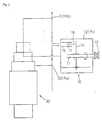
- a variable displacement compressor 10 as shown in Figs 2 and 3 is used e.g. in a refrigeration cycle of an automobile air conditioner and is co-operating with a displacement control apparatus in the form of a generally indicated solenoid controlled valve 30.
- Two different displacement states are shown (Fig. 2: state of the minimum displacement; Fig. 3: state of the maximum displacement).
- An axis 11 of rotation arranged in a airtight crank chamber 12 is driven by driving pulley 13.
- a swing plate 14 in crank chamber 12 is tilted with respect to axis 11 and swings in accordance with a rotation of axis 11.
- a cylinder 15 is arranged receiving piston 17 for free reciprocation. Piston 17 and swing plate 14 are connected by a rod 18.
- the respective displacement of compressor 10 is varied by solenoid controlled valve 30 and by automatically controlling pressure Pc in correspondence to a variation of pressure Ps and keeps the compressor 10 in a steady operation state of minimum displacement.
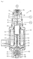
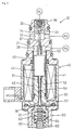
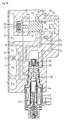
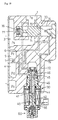
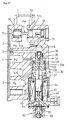
- the solenoid controlled valve 30 of Figs 1, 4 and 5 includes a body tube 31 inserted into a hole (not shown) of coaxial multi-stepped structure formed within a block e.g. enclosing the compressor 10.
- a crank chamber connecting part 32 is arranged which is connected to the crank chamber 12 via a side hole.
- a discharge chamber connecting part 33 is provided connected to the discharge chamber 21 via an opening located at the upper end of body tube 31.
- a valve hole 34 in the centre axis of body tube 31 is provided between crank chamber connecting part 32 and discharge chamber connecting part 33 a valve hole 34 in the centre axis of body tube 31 is provided.
- a spherical valve 35 is provided in discharge chamber connecting part 33 for co-action with the mouth of valve hole 34.
- valve 35 In order to prevent jouncing a weak compression coil spring 36 is provided actuating valve 35 towards the mouth of valve hole 34. In case that a valve driving rod 37 loosely inserted into valve hole 34 is forced upwardly against the force of coil spring 36, valve 35 is pushed into discharge chamber connecting part 33 in order to bring valve 35 into an open state.
- a suction chamber connecting part 38 is provided connected to the suction chamber 20.
- An end side of suction chamber connecting part 38 is situated adjacent to crank chamber connecting part 32.
- an axial penetrating hole slideably receiving the middle part of driving rod 37 is provided.
- Solenoid 40 is secured at a lower flange part of body tube 31 . This is the side of body tube 31 where suction chamber connecting part 38 opens (opposite to the side comprising crank chamber connecting part 32).
- Solenoid 40 comprises an electromagnetic coil 41 and a fixed iron core 42.
- a sleeve 43 is extending containing a moveable iron core 44 which is loosely inserted with radial clearance.
- the lower end of valve driving rod 37 abuts the upper front face of moveable iron core 44.
- Spring 51 has stronger spring force than coil spring 36.
- the spring force of spring 51 is transmitted to valve 35 by means of the moveable iron core 44 and valve driving rod 37. If there is no other power than the force of spring 51 acting on moveable iron core 44 and valve driving rod 37, valve 35 is pushed into its open state.
- a stopper 52 restricts the maximum opening stroke of valve 35.
- Moveable iron core 44 co-acts with a connecting rod 54, the upper end of which either is connected to moveable iron core 44 or simply abuts against it.
- Connecting 54 is loosely inserted into axial penetrating hole 53 of fixed iron core 42.
- a pressure receiving board 55 is fixed.
- a diaphragm 56 is fixed separating the inner part of solenoid 40 containing the pressure Ps from the exterior.
- the external surface of diaphragm 56 is situated in the atmosphere.
- Space 57 confined by diaphragm 56 is connected via penetrating hole 53 to suction chamber connecting part 38. Space 57 can be regarded as a part of suction chamber connecting part 38.
- a pressurising mechanism 60 is associated to serving to load diaphragm 56 from the exterior side with a predetermined reference pressure.
- a spring assembly consisting of compression coil springs 63, 64 is arranged, actuating moveable piston 61 with the necessary force defining said reference pressure. Said urging force of the spring assembly can be finely adjusted by an adjusting screw 65 which in this case only co-acts with inner spring 64.
- the inner surface of diaphragm 56 carries suction chamber pressure Ps.
- the atmospheric pressure and the urging force of springs 63, 64 are carried by the external surface of diaphragm 56.
- Via diaphragm 56 pressure receiving board 55 at the inner surface of diaphragm 56 is receiving a differential pressure of said applied pressures.
- electromagnetic coil 41 is de-energised valve 35 is forced into its open state by the force of spring 51 for operation, and the compressor 10 enters into a state of the minimum displacement.
- diaphragm 56 then only retracts from pressure receiving board 55 towards the exterior side, even when the pressure Ps rises and diaphragm 56 is moving towards the exterior side. Said movement is not transmitted to valve 35. Therefore, valve 35 still remains in its open state and the compressor 10 remains in the steady operation state of the minimum displacement.
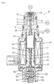
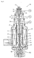
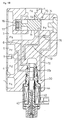
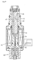
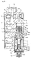
- valve driving rod 37 and connecting rod 54 are formed as a unitary rod supported by bearings 71, 72 in the regions of both ends of said rod.
- bearings 71, 72 leads to small sliding resistance for said rod 37, 54 or said unitary rod, respectively.
- the cross-sectional form of the portion of the unitary rod representing connecting rod 54 is formed as a polygon (e.g. a regular square or hexagon, etc.) so that a clearance is provided between the inner circular surface of bearing 71 and connecting rod 54 so that there is permanent communication between suction chamber connecting part 38 and space 57 through bearing 71 in fixed iron core 42.
- a space 37 at the rear side of valve 35 which in this case is fixed to the upper end of valve driving rod 37 is connected to crank chamber connecting part 32.
- a penetrating hole 74 is axially provided in valve 34.
- An end portion of valve driving rod 37 which is forcibly inserted into penetrating hole 74 has a polygonal cross-section so that there is a clearance between the circular inner wall of penetrating hole 74 and valve driving rod 37.
- valve 35 When electromagnet coil 41 is de-energised, valve 35 is remaining in its open state, regardless of variations of suction chamber pressure Ps so that compressor 10 falls into a steady operation state of the minimum displacement.
- Figs 9 and 10 the solenoid controlled valve 30 constituting the displacement control valve of variable displacement compressor 10 is combined with a suction passage valve 70.
- Variable displacement compressor 10 is used in a refrigeration cycle of an automobile air conditioner.
- Fig. 2 state of minimum displacement
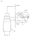
- Fig. 3 state of maximum displacement.
- airtight crank chamber 12 In airtight crank chamber 12 (constituting in this embodiment a pressure control chamber) axis 11 of rotation is driven by driving pulley 13. Swing plate 14 in crank chamber 12 is tilted with respect to axis 11 of rotation and is swinging in accordance with a rotation of axis 11.
- Piston 17 received for reciprocating movement in cylinder 15 in a peripheral part of crank chamber 12 is connected by rod 18 to swing plate 14.
- Pe is the pressure in the low-pressure refrigerant pipe conduit 1; Ps is the pressure in the suction chamber 20 and suction part 3; Pd is the pressure in the discharge chamber 21 and discharge chamber part 4; and Pc is the pressure in the crank chamber 12 and connecting passages 5, 5a, 5b, respectively.
- the angle of inclination of swing plate 14 changes according to pressure Pc.
- the amount of discharge of refrigerant from the cylinder 15 (the capacity of the compressor 10) varies with the angle of inclination of swing plate 14.
- a state of maximum displacement (Fig. 2) occurs when Pc equals Ps.
- the state of minimum displacement (i.e. the minimum operation state) occurs (Fig. 3) when pressure Pc increases.
- Solenoid controlled valve 30 is controlling the displacement of the compressor 10 by automatically controlling the crank chamber pressure Pc in correspondence to a variation of pressure Pe in the low-pressure refrigerant pipe conduit 1 or to a variation of pressure Ps in the suction chamber 20, respectively.
- the control level of valve 30 is varied electromagnetically.
- a connecting pipe 6 extends from low-pressure refrigerant pipe conduit 1 to solenoid controlled valve 30.
- valve 70 In a suction passage between the low-pressure refrigerant pipe conduit 1 and the suction chamber part 3 valve 70 is provided comprising a main valve 71 for opening and closing said suction passage. Valve 70 closes in response to a switching action of the state of solenoid controlled valve 30 in case that valve 30 controls compressor 10 to fall into the minimum operation state.
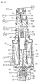
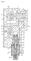
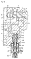
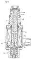
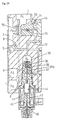
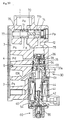
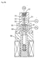
- the valve combination shown in Figs 8, 11, 12 and 13 includes solenoid controlled valve 30 keeping the compressor 10 in the steady operation (minimum operation) state of minimum displacement (shown in Fig. 5).
- First and second crank chamber connecting parts 32a, 32b, are provided in a middle part of body tube 31 adjacent to another Discharge chamber connecting part 33 is situated closer to the upper end of body tube 31.
- Valve hole 34 extending along the axis of body tube 31 interconnects parts 32a, 33.
- valve 35 for opening and closing valve hole 34 is provided in discharge chamber connecting part 33.
- a weak compression coil spring 36 is biasing valve 35 towards the mouth of valve hole 34.
- Valve hole 34 receives loosely inserted valve driving rod 37.
- Valve 35 opens when being pushed by the upper end of valve driving rod 37 counter to the spring force of coil spring 36. In that open state valve 35 is abutting against a valve seat 39 arranged at the opposite side in discharge chamber connecting part 33. Valve seat 39 is arranged at an inlet of a main valve driving connecting hole 32. When valve 35 is separated from valve seat 39 part 33 and hole 72 are communicating and pressure Pp in main valve driving connecting hole 72 becomes equal to pressure Pd.
- a low-pressure connecting part 38 connected to low-pressure refrigerant pipe conduit 1 via a side hole is provided in the lower half part of body tube 31 .
- An end side of connecting part 38 is adjacent to crank chamber connecting part 32b.
- crank chamber connecting part 32b Within a partition wall separating second crank chamber connecting part 32b from low-pressure connecting part 38 an axially penetrating hole is provided.
- a valve rod 37a integrally formed with valve driving rod 37 is provided to open and close said penetrating hole.
- Solenoid 40 is secured to a flange part of body tube 31 in which the low-pressure connecting part 38 is opening (on the opposite side of second crank chamber connecting part 32b).
- Solenoid 40 comprises electromagnetic coil 42, fixed iron core and moveable iron core 44 loosely inserted with clearance in sleeve 43.
- the lower end of valve driving rod 37 abuts against the front face of moveable iron core 44.
- compression coil spring 51 is arranged, the spring force of which is stronger than the spring force of coil spring 36.
- the spring force of coil spring 51 is transmitted to valve 35 via the moveable iron core 44 and valve driving rod 37.
- valve 35 When no other force than the force of spring 51 is acting on moveable iron core 44 and valve driving rod 37, valve 35 is pushed into an open state with respect to valve hole 34. If electromagnetic coil 41 is energised, electromagnetic force is acting in a directional drawing the moveable iron core towards the fixed iron core 42 (Fig. 5) so that valve 35 closes valve hole 34.
- a central penetrating hole 53 is extending receiving loosely inserted connecting rod 54 co-acting with its upper end with moveable iron core 44.
- a pressure receiving board 55 fixed to its other end.
- diaphragm 56 is fixed at the outer edge of fixed iron core 42 and facing pressure receiving board 55 diaphragm 56 is fixed.
- the external surface of diaphragm 56 is open to atmosphere.
- a space 57 above diaphragm 56 is connected to low-pressure connecting part 38 via penetrating hole 53. Space 57 is to be regarded as a pressure chamber and as a part of the low-pressure connecting part 38 which in turn is connected to low pressure refrigerant pipe conduit 1 by connecting pipe 6.
- a pressurising mechanism 60 is associated to, in order to actuate the diaphragm 56 from the exterior side with a reference pressure.
- Compression coil springs 63, 64 defining a spring assembly are situated between fixed member 62 and moveable piston 61 applying an upwardly directed force against diaphragm 56.
- adjusting screw 65 is provided co-acting with spring 64.
- the upper surface of diaphragm 56 detects pressure Pe.
- the lower or external surface of diaphragm 56 detects atmospheric pressure and the forces of springs 63, 64 as a reference pressure.
- pressure receiving board 55 is receiving a differential pressure between those applied pressures by means of diaphragm 56.
- the external surface of the diaphragm 56 may be situated in an airtight space the pressure within which may be used as said reference pressure, instead.
- valve 35 When electromagnetic coil 41 is de-energised spring 51 opens valve 35 which then connects parts 33 and 32a, thereby realising a state (the minimum operation state) in which the compressor 10 maintains its minimum displacement state. At the same time, valve 35 is pushed against valve seat 39 separating hole 72 from part 33. Even if the pressure Pe then rises and the diaphragm is moved towards the exterior side, diaphragm 56 only will retract from pressure receiving board 55 but will not transmit its movement to valve 35. Therefore, valve 35 still remains in its open state and the compressor 10 remains in the steady operation state of minimum displacement.
- main valve 71 of valve 70 is provided midway of a conduit or suction passage connecting low-pressure refrigerant pipe conduit 1 to suction chamber part 3.
- a thin connecting part 71c integrally connects a valve part 71a for opening and closing said suction passage and a driving piston body 72b.
- Valve part 71a and piston body 71b have the same diameter. Pressures applied to the middle part are cancelled or balanced in axial direction.
- Main valve driving connecting hole 72 leads to a cylinder chamber 74 receiving piston part 71b. If valve 35 in is its open state with respect to main valve driving connecting hole 72 pressure Pp within cylinder chamber 74 is approaching pressure Pd (Pp equals Pd).
- Cylinder chamber 74 communicates with suction chamber part 3 via a thin restriction hole or restrictor 75.
- pressure Pp gradually will approach Ps due to restrictor 75 (Pp equals Ps).
- Main valve 71 is actuated in closing direction by compression coil spring 76 counter to applied pressure in cylinder chamber 74.
- Pressure Ps permanently is acting on valve part 71a in a direction counter to the pressure direction in cylinder chamber 74 via a connecting hole 77. Therefore, main valve 71 operates depending upon differential pressure between the action power Fp resulting from pressure Pp in cylinder chamber 74 and the sum of the urging force Fc of compression coil spring 76 and the action power Fs resulting from pressure Ps.
- Main valve 71 enters an open state if Fp>Fc + Fs and enters a closed state if Fp ⁇ Fc + Fs.
- a circumferential groove 78 is formed used to open a reflux hole 79 serving to return pressure from discharge chamber part 4 to low-pressure refrigerant pipe conduit 1.
- Reflux hole 79 is only open when main valve 71 is closed.
- valve 35 When the solenoid 40 or its electromagnetic coil 41, respectively, is energised opening and closing of valve 35 is controlled according to variations of pressure Pe, as mentioned above, and the displacement of the compressor 10 is controlled accordingly. In this state the moveable iron core 44 is drawn towards the fixed iron core 42. Even in the state of the minimum displacement shown in Fig. 13 valve 35 does not close valve seat 39 and pressure Pp in cylinder chamber 74 equals pressure Pd so that valve 70 remains in the open state.
- reflux hole 79 is open via circumferential groove 78.
- the pressure in discharge chamber part 4 is transmitted into low-pressure refrigerant pipe conduit 1 so that the pressure in the latter does not fall too much below a predetermined pressure value. Simultaneously a reflux of the lubricant is realised.
- variable displacement compressor 10 falls into the minimum operation state of minimum displacement.
- valve 70 closes the suction passage.
- the fins of an evaporator (not shown) connected to the compressor do not freeze at a time when the load is small e.g. as in winter, i.e. a situation with low cooling demand.
- restriction hole 7 directly connects discharge chamber part 4 to crank chamber 12.
- the valve seat 39 at the inlet of the main valve driving connecting hole 72 is arranged so that it is located at the former position of valve hole 34 in the preceding embodiment.
- the moving direction of main valve 71 when responding to said pressures is also reversed.
- the shape of main valve 71 is so that it has a long portion located in cylinder chamber 74, meaning that the suction passage between the low-pressure refrigerant pipe conduit 1 and suction chamber part 3 is closed when compression coil spring 76 is compressed.
- Fig. 15 (minimum operation state of the variable displacement compressor) restriction hole 7 directly is connecting discharge chamber part 4 to crank chamber 12.
- Valve seat 39 at the inlet of the main valve driving connecting hole 72 is arranged so as to have a direction opposite to the direction in the preceding embodiment.
- a valve seat 80 is provided between low-pressure refrigerant pipe conduit 1 and suction chamber part 3 .
- Main valve 71 is designed 50 as to abut against the valve seat 80 from the side of the low-pressure refrigerant pipe conduit 1 (upstream side).
- pressure carrying board 81 is connected to the rear end of main valve 71.
- Compression coil spring 76 is provided in cylinder chamber 74 so as to abut against pressure carrying board 81. Pressure in cylinder chamber 74 always becomes equal to pressure Ps in suction chamber part 3 through connecting hole 82 axially arranged in main valve 71.
- Main valve driving connecting hole 72 leads into cylinder chamber 74 in a position allowing to connect it to a side of the pressure carrying board 81 opposite to the side at which the board 81 is loaded by pressure Ps.
- restriction hole 7 directly is connecting discharge chamber part 4 to crank chamber 12.
- pressure Pd here is not used to actuate valve 70.
- pressure Pc instead is applied to main valve driving connecting hole 72 leading into cylinder chamber 74 for the actuation of main valve 71.
- the solenoid controlled valve 30 does not include a valve 35, but instead the function of opening and closing the inlet of the main valve driving connecting hole 72 is carried out by a valve rod 37a directly connected to moveable iron core 44.
- pressure Pc is applied to connecting hole 72.
- Figs 17 and 20 represent the control condition for the state of maximum displacement.
- Figs 18 and 21 represent the control condition for a state of an intermediate displacement.
- Figs 19 and 22 represent the control condition for the minimum operation state in which the state of minimum displacement is maintained.
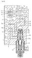
- restriction hole 7 directly is connecting discharge chamber part 4 to connecting passage 5 connected to crank chamber 12.
- Moveable iron core 44 has a pair of spaced apart, circumferential grooves 46. Both grooves 46 are connected by a connecting hole 45 formed within moveable iron core 44.
- Moveable iron core 44 itself fulfils the function of a switch valve for opening or blocking communication between main valve driving connecting hole 72 and connecting passage 5.
- moveable iron core 44 includes an axially penetrating back-pressure cancelling connecting hole 47, so that the same pressures are acting on both ends of moveable iron core 44 and pressure Pe always is acting on the inner surface of diaphragm 56.
- Fig. 23 is representing the control condition in the state of the maximum displacement.
- Fig. 24 is representing the control condition for the state of intermediate displacement.
- Fig. 25 is representing the control condition where the state of the minimum displacement is maintained.
- the main valve 71 is closing the suction passage between the low-pressure refrigerant pipe conduit 1 and suction chamber part 3 when pressure Pp in cylinder chamber 74 is high. Main valve 71 is retracted to open said suction passage when pressure Pp is dropping.
- a restriction hole 75 is formed connecting the inner side of cylinder chamber 74 to suction chamber part 3.
- Valve 35 of solenoid controlled valve 30 driven by solenoid 40 includes a ball-shaped closure member and functions to open and close a passage between discharge chamber part 4 and main valve driving connecting hole 72. Valve 35 is actuated by the upper end of valve driving rod 37. A middle part of valve driving rod 37 is formed as a valve part 37b for opening and closing a passage between connecting passage 5 (to crank chamber 12) and discharge chamber part 4.
- suction pressure Ps is applied to the inner surface of diaphragm 56 via a connecting passage 106.
- the peripheral edge of diaphragm 56 is placed between fixed iron core 42 and a flange 69 of the pressurising mechanism.
- the outer edge of the diaphragm 56 is fixed from the outside by laser welding, etc. Therefore, the diaphragm 56 can be made of metal. This can be realised as well in the other embodiments.
- the peripheral part of diaphragm 56 is located between fixed iron core 42 and the flange 69 of the pressurising mechanism and is fixed by laser welding, etc., from the exterior side.
- a restriction hole 132 is connecting a central side hole 133 permanently connected to main valve driving connecting hole 72 and the part connected to the discharge chamber part 4 with a small sectional area.
- Valve rod 37a is designed, e.g. with a shoulder, in order to open to close a passage between the central side hole 133 and the suction chamber part 4 depending on the stroke position of valve driving rod 37.
- valve 35 Since the opening or closing timing of valve 35 is shifting in correspondence to the value of the energising current supplied to electromagnetic coil 41 the amount of discharge can be arbitrarily shifted corresponding to the value of suction pressure Ps.
- valve 35 In the embodiment of the valve combination according to Figs 29 and 30 (Fig. 29: control condition at the state of intermediate displacement; Fig. 30: control condition at the minimum operation state where a state of minimum displacement is maintained) the piping provided upstream and downstream of valve 35 is reversed compared with the preceding embodiment (to a piping arrangement as in one of the preceding embodiments).
- the structure of valve 35 is the same as in the embodiment of Fig. 8.
- the inside of cylinder chamber 74 of valve 70 permanently is connected to suction chamber part 3 via main valve driving connecting hole 72 and restriction hole 75. Communication between suction chamber part 3 and cylinder chamber 74 is opened or blocked by valve 35, the upper and lower portions of which have conical shapes in this embodiment.
- Central side hole 133 permanently is connected to connecting passage 5.
- Restriction hole 8 formed in the body tube 131 of solenoid controlled valve 30 is formed to open a passage between the central side hole 133 and suction chamber part 3. Suction pressure Ps is applied to the inner surface of diaphragm 56 by way of connecting passage 106.
- valve 35 can be shifted in correspondence to the value of the energising current for solenoid 40. As a consequence, the amount of discharge corresponding to the value of suction pressure Ps arbitrarily can be shifted as well.
- the present invention is not limited to the embodiments as shown and described. It can be realised in any mode, provided that, when the solenoid 40 of the solenoid controlled valve 30 is de-energised, the variable displacement compressor 10 will fall into the minimum operation state, and in response to that, the valve 70 will close the suction passage between the low-pressure refrigerant pipe conduit 1 and the suction chamber part 3.
- the invention cannot only be applied to a variable displacement compressor having a swing or wobble plate, as shown, but also to various types of variable displacement compressors like a rotary type - or a scroll type variable displacement compressor, etc.
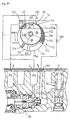
- a variable displacement compressor 110 of a rotary type is equipped with the solenoid controlled valve 30 for displacement control and the valve 70 as shown in Figs 27 and 28.
- Fig. 31 is representing the minimum operation state.
- the variable displacement compressor 110 shown is already known.
- a circular rotor 112 of smaller size than the housing is arranged so as to be centred on an eccentric axis 113 which is driven for rotation by an engine, etc., not shown.
- At the periphery of rotor 112 with intervals of 90° four seal members 114 are arranged which are loaded by springs (not shown) towards the outer side so as to be in permanent contact with the inner surface of housing 111.
- the inner surface of the housing 111 and the outer surface of rotor 112 are almost in contact with another at one rotary position of the rotor where the outer surface of rotor 112 approaches the inner surface of housing 111 nearest. In this region a discharge opening 119 is formed through which compressed refrigerant is discharged.
- Adjacent rotor 112 a suction opening control plate 115 is rotatably provided in contact with housing 111.
- a suction opening 115a in suction opening control plate 115 is connected to suction chamber part 3.
- the low-pressure refrigerant is sucked into compressor 110.
- On suction opening control plate 115 a protruding driving pin 117 is provided driven by a displacement varying mechanism 130.
- Pin 117 allows to change the position of suction opening control plate 115 causing displacement of the suction opening 115a.
- a hole 116 is formed with a deformed circular shape in order to avoid interference with eccentric axis 113.
- Mechanism 130 includes a piston 132 in a cylinder 131 for reciprocal movement along the axis of the cylinder. The driving pin 117 is engaging into a ditch 132a formed on the surface of piston 132.
- cylinder 131 One side of cylinder 131 is connected to suction chamber part 3 so that the pressure in cylinder 131 is equal to suction pressure Ps.
- a pressure control spring 133 is provided inside the pressure chamber actuating piston 132.
- the other end of cylinder 131 is defining a pressure control chamber 131a connected to connecting passage 5.
- the internal pressure Pc of pressure control chamber 131a is controlled by solenoid controlled valve 30.
- the amount of discharge (displacement) of the variable displacement compressor 110 of the rotary type is varied by changing the position of suction opening control plate 115 in correspondence to pressure Pc inside pressure control chamber 131a.
- a control function is executed which is quite similar to the control function as described for the variable displacement compressor of the swing plate type, namely by solenoid controlled valve 30 and valve 70 according to the invention.
- Fig. 32 is representing a prior art solenoid controlled valve of a conventional displacement control apparatus for a variable displacement compressor.
- a crank chamber connecting part 91 is connected to a discharge chamber connecting part 92 via a valve hole 93.
- Valve closure member 94 is co-operating with valve hole 93 for opening and closing valve hole 93.
- Adjacent to crank chamber connecting part 91 a suction chamber connecting part 95 is provided at a side opposite to the side where the discharge chamber connecting part 92 is connected.
- Pd represents the discharge chamber pressure
- Pc represents the crank chamber pressure
- Ps represents the suction chamber pressure.
- a spring 97 is urging valve pressure member 94 in opening direction and via a valve driving rod 96 penetrating valve hole 93.
- a solenoid 98 serves to generate electromagnetic force to drive valve driving rod 96 downwardly to close valve 93, 94.
- a pressure sensitive part 99 is provided in suction chamber connecting part 95, especially between the solenoid 98 and crank chamber connecting part 91.
- the pressure sensitive part 99 comprises a bellows connected to the moveable core of the solenoid 98 and the spring 97 inside the bellows. Both the bellows and the spring 97 are co-acting with a plate co-operating with valve driving rod 96.
- a certain pressure inside the bellows may define a predetermined reference pressure.
- the pressure sensitive part 99 responds to the differential pressure between said predetermined reference pressure and pressure Ps to move valve driving rod 96 to close (or open) valve 93, 94.
- valve 93, 94 opening and closing of valve 93, 94 is controlled by pressure sensitive part 99 operating in correspondence of pressure Ps whereby the displacement of the compressor is controlled.
- the value of pressure Ps responsible for opening or closing valve 93, 94 can be varied by changing the value of the energising current for solenoid 98.
- the solenoid 98 is de-energised, thereby maximising the possible stroke of valve 93, 94.
- the force of pressure sensitive part 99 is acting on valve driving rod 96 causing to open or close valve 93, 94 even with solenoid 98 de-energised and still in correspondence to variations of pressure Ps in the suction chamber.
Landscapes
- Engineering & Computer Science (AREA)
- Mechanical Engineering (AREA)
- General Engineering & Computer Science (AREA)
- Compressors, Vaccum Pumps And Other Relevant Systems (AREA)
- Control Of Positive-Displacement Pumps (AREA)
Applications Claiming Priority (10)
| Application Number | Priority Date | Filing Date | Title |
|---|---|---|---|
| JP28614798A JP3993708B2 (ja) | 1998-10-08 | 1998-10-08 | 容量可変圧縮機の容量制御装置 |
| JP28614798 | 1998-10-08 | ||
| JP33060898 | 1998-11-20 | ||
| JP33060898 | 1998-11-20 | ||
| JP8077299 | 1999-03-25 | ||
| JP8077299 | 1999-03-25 | ||
| JP13208199 | 1999-05-13 | ||
| JP13208199 | 1999-05-13 | ||
| JP16030799 | 1999-06-08 | ||
| JP16030799A JP3792939B2 (ja) | 1998-11-20 | 1999-06-08 | 容量可変圧縮機及び容量制御弁 |
Publications (2)
| Publication Number | Publication Date |
|---|---|
| EP0992684A2 true EP0992684A2 (fr) | 2000-04-12 |
| EP0992684A3 EP0992684A3 (fr) | 2001-01-17 |
Family
ID=27524879
Family Applications (1)
| Application Number | Title | Priority Date | Filing Date |
|---|---|---|---|
| EP99119778A Withdrawn EP0992684A3 (fr) | 1998-10-08 | 1999-10-06 | Soupape de contrôle magnétique pour un compresseur à capacité variable |
Country Status (2)
| Country | Link |
|---|---|
| US (1) | US6302656B1 (fr) |
| EP (1) | EP0992684A3 (fr) |
Cited By (12)
| Publication number | Priority date | Publication date | Assignee | Title |
|---|---|---|---|---|
| EP1091124A3 (fr) * | 1999-10-04 | 2003-01-02 | Fujikoki Corporation | Soupape de régulation pour un compresseur à capacité variable |
| EP1197660A3 (fr) * | 2000-10-17 | 2004-01-02 | Fujikoki Corporation | Soupape de commande pour un compresseur à capacité variable |
| US6688853B1 (en) | 2001-01-08 | 2004-02-10 | Honeywell International Inc. | Control valve for regulating flow between two chambers relative to another chamber |
| EP1186776A3 (fr) * | 2000-09-05 | 2004-04-14 | Kabushiki Kaisha Toyota Jidoshokki | Soupape de régulation d'un compresseur à capacité variable |
| EP1462696A1 (fr) * | 2003-03-27 | 2004-09-29 | Pacific Industrial Co., Ltd. | Soupape de commande et méthode pour construire la même |
| EP1591661A2 (fr) | 2004-04-28 | 2005-11-02 | Kabushiki Kaisha Toyota Jidoshokki | Compresseur à déplacement variable |
| EP1221392A3 (fr) * | 2001-01-09 | 2005-12-28 | Kabushiki Kaisha Toyota Jidoshokki | Système de climatisation pour véhicule et son procédé de contrôle |
| EP1895163A1 (fr) * | 2006-08-21 | 2008-03-05 | Kabushiki Kaisha Toyota Jidoshokki | Structure pour détecter le débit de réfrigérant dans un compresseur |
| WO2009106267A1 (fr) * | 2008-02-27 | 2009-09-03 | Ixetic Mac Gmbh | Compresseur d'agent réfrigérant |
| EP2136080A1 (fr) * | 2008-06-17 | 2009-12-23 | Delphi Technologies, Inc. | Compresseur à déplacement variable avec soupape d'arrêt d'aspiration compensée par pression de décharge |
| EP1712792A3 (fr) * | 2005-04-12 | 2011-01-19 | Fujikoki Corporation | Soupape de contrôle pour compresseur à capacité variable |
| CN103363103B (zh) * | 2012-03-28 | 2016-06-01 | 加特可株式会社 | 自动变速器的油压控制装置 |
Families Citing this family (10)
| Publication number | Priority date | Publication date | Assignee | Title |
|---|---|---|---|---|
| JP3963619B2 (ja) * | 1999-11-05 | 2007-08-22 | 株式会社テージーケー | 冷凍サイクルの圧縮容量制御装置 |
| US6746214B2 (en) * | 2001-03-01 | 2004-06-08 | Pacific Industrial Co., Ltd. | Control valve for compressors and manufacturing method thereof |
| JP3911443B2 (ja) * | 2002-05-27 | 2007-05-09 | 太平洋工業株式会社 | 制御弁 |
| KR100984214B1 (ko) * | 2003-01-22 | 2010-09-28 | 가부시키가이샤 발레오 서멀 시스템즈 | 가변 용량 압축기의 제어 밸브 |
| JP2005351207A (ja) * | 2004-06-11 | 2005-12-22 | Tgk Co Ltd | 可変容量圧縮機用制御弁 |
| DE202006002243U1 (de) * | 2006-02-10 | 2006-04-20 | Lincoln Gmbh & Co. Kg | Hydraulische Vorrichtung mit Schmierpumpe |
| JP5123715B2 (ja) * | 2008-04-07 | 2013-01-23 | カルソニックカンセイ株式会社 | 斜板式圧縮機 |
| CN105041630B (zh) * | 2015-07-08 | 2017-01-25 | 浙江三花汽车零部件有限公司 | 一种变排量压缩机用电磁控制阀 |
| JP2018071481A (ja) * | 2016-11-01 | 2018-05-10 | サンデン・オートモーティブコンポーネント株式会社 | スクロール型流体機械 |
| KR102692484B1 (ko) * | 2019-05-20 | 2024-08-07 | 현대자동차주식회사 | 차량의 공기조화 시스템, 공기조화 시스템용 전자제어밸브 및 공기조화 시스템의 제어방법 |
Family Cites Families (9)
| Publication number | Priority date | Publication date | Assignee | Title |
|---|---|---|---|---|
| JPS6365178A (ja) * | 1986-09-05 | 1988-03-23 | Toyota Autom Loom Works Ltd | 流体の制御機構 |
| SG30647G (en) * | 1991-01-28 | 1995-09-01 | Sanden Corp | Slant plate type compressor with variable displacement mechanism |
| JPH08109880A (ja) * | 1994-10-11 | 1996-04-30 | Toyota Autom Loom Works Ltd | 可変容量型圧縮機の動作制御システム |
| US5702235A (en) * | 1995-10-31 | 1997-12-30 | Tgk Company, Ltd. | Capacity control device for valiable-capacity compressor |
| JP3432995B2 (ja) * | 1996-04-01 | 2003-08-04 | 株式会社豊田自動織機 | 可変容量型圧縮機用制御弁 |
| US6010312A (en) * | 1996-07-31 | 2000-01-04 | Kabushiki Kaisha Toyoda Jidoshokki Seiksakusho | Control valve unit with independently operable valve mechanisms for variable displacement compressor |
| JPH10141219A (ja) * | 1996-11-11 | 1998-05-26 | Sanden Corp | 可変容量圧縮機 |
| KR100302820B1 (ko) * | 1997-01-21 | 2002-02-28 | 이시카와 타다시 | 가변용량압축기용제어밸브및장착방법 |
| JP4160669B2 (ja) * | 1997-11-28 | 2008-10-01 | 株式会社不二工機 | 可変容量型圧縮機用制御弁 |
-
1999
- 1999-10-05 US US09/412,144 patent/US6302656B1/en not_active Expired - Fee Related
- 1999-10-06 EP EP99119778A patent/EP0992684A3/fr not_active Withdrawn
Cited By (17)
| Publication number | Priority date | Publication date | Assignee | Title |
|---|---|---|---|---|
| EP1091124A3 (fr) * | 1999-10-04 | 2003-01-02 | Fujikoki Corporation | Soupape de régulation pour un compresseur à capacité variable |
| EP1186776A3 (fr) * | 2000-09-05 | 2004-04-14 | Kabushiki Kaisha Toyota Jidoshokki | Soupape de régulation d'un compresseur à capacité variable |
| EP1197660A3 (fr) * | 2000-10-17 | 2004-01-02 | Fujikoki Corporation | Soupape de commande pour un compresseur à capacité variable |
| US6688853B1 (en) | 2001-01-08 | 2004-02-10 | Honeywell International Inc. | Control valve for regulating flow between two chambers relative to another chamber |
| EP1221392A3 (fr) * | 2001-01-09 | 2005-12-28 | Kabushiki Kaisha Toyota Jidoshokki | Système de climatisation pour véhicule et son procédé de contrôle |
| EP1462696A1 (fr) * | 2003-03-27 | 2004-09-29 | Pacific Industrial Co., Ltd. | Soupape de commande et méthode pour construire la même |
| US6971629B2 (en) | 2003-03-27 | 2005-12-06 | Pacific Industrial Co., Ltd. | Control valve and method of making the same |
| US7648346B2 (en) | 2004-04-28 | 2010-01-19 | Kabushiki Kaisha Toyota Jidoshokki | Variable displacement compressor |
| EP1591661A3 (fr) * | 2004-04-28 | 2009-08-12 | Kabushiki Kaisha Toyota Jidoshokki | Compresseur à déplacement variable |
| EP1591661A2 (fr) | 2004-04-28 | 2005-11-02 | Kabushiki Kaisha Toyota Jidoshokki | Compresseur à déplacement variable |
| EP1712792A3 (fr) * | 2005-04-12 | 2011-01-19 | Fujikoki Corporation | Soupape de contrôle pour compresseur à capacité variable |
| EP1895163A1 (fr) * | 2006-08-21 | 2008-03-05 | Kabushiki Kaisha Toyota Jidoshokki | Structure pour détecter le débit de réfrigérant dans un compresseur |
| US8186172B2 (en) | 2006-08-21 | 2012-05-29 | Kabushiki Kaisha Toyota Jidoshokki | Structure for sensing refrigerant flow rate in a compressor |
| WO2009106267A1 (fr) * | 2008-02-27 | 2009-09-03 | Ixetic Mac Gmbh | Compresseur d'agent réfrigérant |
| EP2136080A1 (fr) * | 2008-06-17 | 2009-12-23 | Delphi Technologies, Inc. | Compresseur à déplacement variable avec soupape d'arrêt d'aspiration compensée par pression de décharge |
| US8277200B2 (en) | 2008-06-17 | 2012-10-02 | Delphi Technologies, Inc. | Variable displacement compressor with a discharge pressure compensated suction shutoff valve |
| CN103363103B (zh) * | 2012-03-28 | 2016-06-01 | 加特可株式会社 | 自动变速器的油压控制装置 |
Also Published As
| Publication number | Publication date |
|---|---|
| US6302656B1 (en) | 2001-10-16 |
| EP0992684A3 (fr) | 2001-01-17 |
Similar Documents
| Publication | Publication Date | Title |
|---|---|---|
| EP0992684A2 (fr) | Soupape de contrôle magnétique pour un compresseur à capacité variable | |
| EP1098091B1 (fr) | Régulation du débit d'un compresseur dans un circuit de réfrigération | |
| JP4162419B2 (ja) | 可変容量圧縮機 | |
| CA2086271C (fr) | Compresseur a plateau incline avec controle a capacite variable et mecanisme de soupape de surete | |
| EP1333177B1 (fr) | Soupape de contrôle de capacité | |
| JP3728387B2 (ja) | 制御弁 | |
| CA2128368C (fr) | Structure a paliers pour compresseur | |
| US6149398A (en) | Variable capacity piston- operated refrigerant compressor with an oil separating means | |
| EP1024285A2 (fr) | Soupape de contrôle pour compresseur à capacité variable | |
| EP0824191B1 (fr) | Compresseur à déplacement variable | |
| EP1561948A2 (fr) | Soupape de contrôle pour un compresseur à capacité variable | |
| EP0945617A2 (fr) | Soupape de contrÔle d'un compresseur à capacité variable | |
| US6217293B1 (en) | Variable displacement compressor | |
| EP1041281A2 (fr) | Compresseur à capacité variable | |
| JPH04259683A (ja) | 斜板式コンプレッサー | |
| EP1602828A2 (fr) | Soupape de contrôle pour un compresseur à capacité variable | |
| US7387501B2 (en) | Control valve for variable displacement compressor | |
| EP1605161A2 (fr) | Soupape de contrôle pour un compresseur à capacité variable | |
| US6416297B1 (en) | Stopping means for preventing movement of the drive shaft of a variable displacement compressor | |
| KR100726752B1 (ko) | 무클러치 가변 용량형 압축기용 용량 제어 밸브 | |
| US6783332B2 (en) | Control valve of variable displacement compressor with pressure sensing member | |
| EP1033489A2 (fr) | Soupape de contrôle pour compresseurs à capacité variable | |
| EP1026398A2 (fr) | Soupape de contrôle de débit d'un compresseur à capacité variable | |
| KR20060050534A (ko) | 가변 용량 압축기용 제어 밸브 | |
| JP3792939B2 (ja) | 容量可変圧縮機及び容量制御弁 |
Legal Events
| Date | Code | Title | Description |
|---|---|---|---|
| PUAI | Public reference made under article 153(3) epc to a published international application that has entered the european phase |
Free format text: ORIGINAL CODE: 0009012 |
|
| AK | Designated contracting states |
Kind code of ref document: A2 Designated state(s): DE ES FR GB IT |
|
| AX | Request for extension of the european patent |
Free format text: AL;LT;LV;MK;RO;SI |
|
| PUAL | Search report despatched |
Free format text: ORIGINAL CODE: 0009013 |
|
| RIC1 | Information provided on ipc code assigned before grant |
Free format text: 7F 04B 27/18 A, 7F 04B 49/22 B |
|
| AK | Designated contracting states |
Kind code of ref document: A3 Designated state(s): AT BE CH CY DE DK ES FI FR GB GR IE IT LI LU MC NL PT SE |
|
| AX | Request for extension of the european patent |
Free format text: AL;LT;LV;MK;RO;SI |
|
| 17P | Request for examination filed |
Effective date: 20001221 |
|
| AKX | Designation fees paid |
Free format text: DE ES FR GB IT |
|
| STAA | Information on the status of an ep patent application or granted ep patent |
Free format text: STATUS: THE APPLICATION IS DEEMED TO BE WITHDRAWN |
|
| 18D | Application deemed to be withdrawn |
Effective date: 20060117 |