EP0994246A2 - Brennkraftmaschinensteuerung mit modelbasiertem barometrischen Druckabschätzer - Google Patents
Brennkraftmaschinensteuerung mit modelbasiertem barometrischen Druckabschätzer Download PDFInfo
- Publication number
- EP0994246A2 EP0994246A2 EP99203062A EP99203062A EP0994246A2 EP 0994246 A2 EP0994246 A2 EP 0994246A2 EP 99203062 A EP99203062 A EP 99203062A EP 99203062 A EP99203062 A EP 99203062A EP 0994246 A2 EP0994246 A2 EP 0994246A2
- Authority
- EP
- European Patent Office
- Prior art keywords
- intake system
- determined
- determining
- pressure
- intake
- Prior art date
- Legal status (The legal status is an assumption and is not a legal conclusion. Google has not performed a legal analysis and makes no representation as to the accuracy of the status listed.)
- Withdrawn
Links
- 238000002485 combustion reaction Methods 0.000 title claims description 23
- 238000000034 method Methods 0.000 claims abstract description 20
- 238000013178 mathematical model Methods 0.000 claims abstract description 4
- 239000007789 gas Substances 0.000 claims description 53
- 239000000446 fuel Substances 0.000 claims description 21
- 238000010926 purge Methods 0.000 claims description 16
- 230000008859 change Effects 0.000 claims description 5
- 230000004044 response Effects 0.000 claims description 5
- 238000004364 calculation method Methods 0.000 abstract description 2
- 239000003570 air Substances 0.000 description 56
- 230000006870 function Effects 0.000 description 16
- 239000002828 fuel tank Substances 0.000 description 13
- 238000010586 diagram Methods 0.000 description 11
- GIMSJJHKKXRFGV-BYPJNBLXSA-N 4-amino-1-[(2r,3s,4r,5r)-3-fluoro-4-hydroxy-5-(hydroxymethyl)oxolan-2-yl]-5-iodopyrimidin-2-one Chemical compound C1=C(I)C(N)=NC(=O)N1[C@H]1[C@@H](F)[C@H](O)[C@@H](CO)O1 GIMSJJHKKXRFGV-BYPJNBLXSA-N 0.000 description 3
- IJGRMHOSHXDMSA-UHFFFAOYSA-N Atomic nitrogen Chemical compound N#N IJGRMHOSHXDMSA-UHFFFAOYSA-N 0.000 description 2
- 238000013459 approach Methods 0.000 description 2
- 230000003197 catalytic effect Effects 0.000 description 2
- 238000012937 correction Methods 0.000 description 2
- 238000002405 diagnostic procedure Methods 0.000 description 2
- 238000002347 injection Methods 0.000 description 2
- 239000007924 injection Substances 0.000 description 2
- 238000012423 maintenance Methods 0.000 description 2
- 238000002156 mixing Methods 0.000 description 2
- 238000012986 modification Methods 0.000 description 2
- 230000004048 modification Effects 0.000 description 2
- 238000011144 upstream manufacturing Methods 0.000 description 2
- 238000009834 vaporization Methods 0.000 description 2
- 230000008016 vaporization Effects 0.000 description 2
- 239000012080 ambient air Substances 0.000 description 1
- 238000004422 calculation algorithm Methods 0.000 description 1
- 239000003610 charcoal Substances 0.000 description 1
- 238000004590 computer program Methods 0.000 description 1
- 238000011217 control strategy Methods 0.000 description 1
- 238000007435 diagnostic evaluation Methods 0.000 description 1
- 238000010790 dilution Methods 0.000 description 1
- 239000012895 dilution Substances 0.000 description 1
- 238000001914 filtration Methods 0.000 description 1
- 230000010354 integration Effects 0.000 description 1
- 238000012886 linear function Methods 0.000 description 1
- 239000000314 lubricant Substances 0.000 description 1
- 239000000203 mixture Substances 0.000 description 1
- 229910052757 nitrogen Inorganic materials 0.000 description 1
- 238000012545 processing Methods 0.000 description 1
- 238000011084 recovery Methods 0.000 description 1
- 230000009467 reduction Effects 0.000 description 1
- 230000000717 retained effect Effects 0.000 description 1
- 230000001360 synchronised effect Effects 0.000 description 1
- 238000010998 test method Methods 0.000 description 1
- 238000012546 transfer Methods 0.000 description 1
- 238000009423 ventilation Methods 0.000 description 1
Images

Classifications
-
- F—MECHANICAL ENGINEERING; LIGHTING; HEATING; WEAPONS; BLASTING
- F02—COMBUSTION ENGINES; HOT-GAS OR COMBUSTION-PRODUCT ENGINE PLANTS
- F02D—CONTROLLING COMBUSTION ENGINES
- F02D41/00—Electrical control of supply of combustible mixture or its constituents
- F02D41/0025—Controlling engines characterised by use of non-liquid fuels, pluralities of fuels, or non-fuel substances added to the combustible mixtures
- F02D41/0047—Controlling exhaust gas recirculation [EGR]
- F02D41/0065—Specific aspects of external EGR control
- F02D41/0072—Estimating, calculating or determining the EGR rate, amount or flow
-
- F—MECHANICAL ENGINEERING; LIGHTING; HEATING; WEAPONS; BLASTING
- F02—COMBUSTION ENGINES; HOT-GAS OR COMBUSTION-PRODUCT ENGINE PLANTS
- F02D—CONTROLLING COMBUSTION ENGINES
- F02D41/00—Electrical control of supply of combustible mixture or its constituents
- F02D41/02—Circuit arrangements for generating control signals
- F02D41/18—Circuit arrangements for generating control signals by measuring intake air flow
-
- F—MECHANICAL ENGINEERING; LIGHTING; HEATING; WEAPONS; BLASTING
- F02—COMBUSTION ENGINES; HOT-GAS OR COMBUSTION-PRODUCT ENGINE PLANTS
- F02D—CONTROLLING COMBUSTION ENGINES
- F02D41/00—Electrical control of supply of combustible mixture or its constituents
- F02D41/30—Controlling fuel injection
- F02D41/32—Controlling fuel injection of the low pressure type
-
- F—MECHANICAL ENGINEERING; LIGHTING; HEATING; WEAPONS; BLASTING
- F02—COMBUSTION ENGINES; HOT-GAS OR COMBUSTION-PRODUCT ENGINE PLANTS
- F02D—CONTROLLING COMBUSTION ENGINES
- F02D2200/00—Input parameters for engine control
- F02D2200/02—Input parameters for engine control the parameters being related to the engine
- F02D2200/04—Engine intake system parameters
- F02D2200/0402—Engine intake system parameters the parameter being determined by using a model of the engine intake or its components
-
- F—MECHANICAL ENGINEERING; LIGHTING; HEATING; WEAPONS; BLASTING
- F02—COMBUSTION ENGINES; HOT-GAS OR COMBUSTION-PRODUCT ENGINE PLANTS
- F02D—CONTROLLING COMBUSTION ENGINES
- F02D2200/00—Input parameters for engine control
- F02D2200/02—Input parameters for engine control the parameters being related to the engine
- F02D2200/04—Engine intake system parameters
- F02D2200/0406—Intake manifold pressure
- F02D2200/0408—Estimation of intake manifold pressure
-
- F—MECHANICAL ENGINEERING; LIGHTING; HEATING; WEAPONS; BLASTING
- F02—COMBUSTION ENGINES; HOT-GAS OR COMBUSTION-PRODUCT ENGINE PLANTS
- F02D—CONTROLLING COMBUSTION ENGINES
- F02D2200/00—Input parameters for engine control
- F02D2200/70—Input parameters for engine control said parameters being related to the vehicle exterior
- F02D2200/703—Atmospheric pressure
- F02D2200/704—Estimation of atmospheric pressure
-
- Y—GENERAL TAGGING OF NEW TECHNOLOGICAL DEVELOPMENTS; GENERAL TAGGING OF CROSS-SECTIONAL TECHNOLOGIES SPANNING OVER SEVERAL SECTIONS OF THE IPC; TECHNICAL SUBJECTS COVERED BY FORMER USPC CROSS-REFERENCE ART COLLECTIONS [XRACs] AND DIGESTS
- Y02—TECHNOLOGIES OR APPLICATIONS FOR MITIGATION OR ADAPTATION AGAINST CLIMATE CHANGE
- Y02T—CLIMATE CHANGE MITIGATION TECHNOLOGIES RELATED TO TRANSPORTATION
- Y02T10/00—Road transport of goods or passengers
- Y02T10/10—Internal combustion engine [ICE] based vehicles
- Y02T10/40—Engine management systems
Definitions
- This invention relates to the control of an internal combustion engine based on an estimate of barometric pressure, including a model-based control method for accurately estimating the barometric pressure.
- barometric pressure is desired in order to accurately perform control and diagnostic functions of an automotive power plant, including fuel injection and vapor purge controls.
- the barometric pressure may be measured directly with a dedicated sensor, many automotive manufacturers have relied on an estimate of the barometric pressure in order to save the cost of the sensor.
- the pressure estimation is typically based on the measured intake manifold pressure, with a variable adjustment or offset heuristically determined in relation to engine operating parameters such as speed and load. While this approach eliminates the sensor, the accuracy of the estimate tends to vary with operating conditions, and extensive calibration is required in order to provide acceptable accuracy at high altitudes. Accordingly, what is needed is an approach that is accurate over a wide range of operation and that requires only minimal effort to calibrate.
- the present invention is directed to an improved engine control utilizing a model-based technique to obtain an accurate estimate of barometric pressure with significantly reduced calibration time and effort.
- a mathematical model of mass air flow through the engine intake system is used to estimate the pressure ratio across the intake system (that is, the ratio of barometric pressure to intake manifold pressure) as a function of mass air flow, the effective intake area, the intake manifold pressure and the intake air temperature.
- the barometric pressure is then determined from the estimated ratio, and used in the calculation of various gas flows for control purposes.
- the mass air flow information is provided by a mass air flow sensor.
- the mass air flow information is determined based on engine flow rate estimations.
- simple 2-D look-up tables are used to determine the effective intake area based on throttle and idle air control (if applicable) position, and a single 3-D look-up table is used to estimate the pressure ratio across the intake system as a function of effective intake area and mass air flow parameters. Because the estimation is model-based, no special calibration is needed to ensure accuracy at high altitudes.
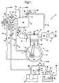
- the reference numeral 10 generally designates a conventional internal combustion engine system.
- the engine system 10 includes various sensors and actuators, described in reference to Figure 1, which are coupled to an electronic controller (Controller 214) as diagramatically shown in Figure 2.
- the engine system 10 is diagrammed as an interdependent network of gas mass flows designated by arrows labeled F 1 - F 16 between a network of pneumatic volume nodes designated as N1 - N7 .
- Inlet air at atmospheric, or barometric, pressure P at at node N1 passes through fresh air inlet 11, through air cleaner 13 and into intake duct 15 at node N2 .
- the inlet air is drawn through throttle body 17 in which is rotatably disposed a throttle plate 19, the position of which is manually or electronically controlled to vary restriction to inlet air passing through the throttle body 17.
- the position of throttle plate 19 is detected by the sensor 18 and provides as an input (TP) to the Controller 214.
- a portion of inlet air is routed past throttle plate 19 trough conduits 59 and 61 and a conventional idle air bypass valve 60.
- the bypass valve 60 may be electrically controlled by an internal stepper motor (not shown) in response to an idle air command signal from the Controller 214 on line 81 under engine idle conditions when a precise control of relatively low intake airflow is required.
- the position of the valve 60 may be known to the Controller 214 based on the number of incremental movements or steps of the bypass valve 60 from a known limit position.
- Airflow out of throttle body 17 is coupled through intake duct 21 into intake manifold 23 at node N3 .
- a conventional pressure transducer 24 is exposed to gas pressure in the intake manifold 23 and provides a manifold absolute pressure (MAP) signal in accordance therewith on line 12.
- MAP manifold absolute pressure
- Individual cylinder intake runners one runner 25 being illustrated in Figure 1, open into the intake manifold 23 and into the combustion chamber of respective engine cylinders, one combustion chamber 31 of one respective cylinder 30 being shown in Figure 1.
- Each cylinder includes a combustion chamber 31 and crankcase 33, separated by a piston 34 which engages the inside wall of the cylinder.
- a quantity of fuel is injected into the intake runner 25 via conventional fuel injector 87 in response to a fuel injection command signal from the Controller 214 on line 88.
- the fuel mixes with the inlet air and is drawn into the combustion chamber 31 during a cylinder intake event during which an intake valve 26 is driven to an open position and during which a low pressure condition is present in the combustion chamber 31.
- the air-fuel mixture is ignited in the combustion chamber 31 during a combustion event initiated by a timed ignition arc across the spaced electrodes of spark plug 32 in response to the Controller 214.
- the piston 34 within the cylinder 30 is reciprocally driven under the effective pressure of the combustion event for driving vehicle wheels, accessory loads, etc., as is generally understood in the art.
- Gasses produced in the combustion process within the combustion chamber 31 are exhausted from the combustion chamber 31 during a cylinder exhaust event and through exhaust runner 27 to exhaust manifold 29 at node N5 .
- the exhaust gasses pass through the exhaust manifold 29 to exhaust duct 35 leading to catalytic treatment device and muffler (generally illustrated as element 37) and then to the atmosphere at the pressure of node N1 .
- Vacuum is selectively applied to the cylinder crankcase 33 at node N4 through a positive crankcase ventilation (PCV) conduit 49 including a standard PCV valve 51, the PCV conduit being connected between the crankcase 33 and the intake duct 21.
- the intake vacuum serves to draw out blow-by gasses that have been driven from the cylinder combustion chamber 31 to the crankcase 33 under the pressure of the combustion process.
- a supply of fresh inlet air from node N2 is provided to the crankcase 33 via a fresh air conduit 63 connected between the intake duct 15 and the crankcase 33.
- the PCV valve selectively draws the blow-by gasses from the crankcase 33 for mixing with intake air for consumption in engine cylinders 30 for purifying engine system lubricants.
- a portion of the exhaust gasses are drawn from the exhaust manifold 29 at node N5 through an exhaust gas recirculation (EGR) conduit 43 and across an EGR valve 41 and a conduit 45 into the intake manifold 23 at node N3 for mixing with inlet air for delivery to the engine cylinder combustion chambers.
- the EGR valve 41 is electrically operated by the Controller 214 via line 83 as is generally understood in the art in response to general operating conditions to vary the dilution of the fresh inlet air with substantially inert exhaust gas to provide for a reduction in the engine emissions component of oxides of nitrogen (NOx).
- NOx oxides of nitrogen
- a pneumatic brake boost conduit 47 opens into intake manifold 23 at node N3 providing for a minor gas flow F 16 during application of the vehicle service brakes (not shown) as is well-known in the art.
- Vehicles equipped with well-known evaporative emission controls may also have gas flow through a canister purge valve 53 and canister purge conduits 55 and 57 into throttle body 17 downstream of throttle plate 19.
- Charcoal canister 65 generally releases fuel vapors when fresh air is drawn through purge vent 67 and purge vent conduits 69 and 71.
- Fuel tank 75 may also release fuel vapors which may be absorbed in canister 65, may be released thereby, or may pass directly to the engine along with released fuel vapors through conduit 55 at node N6 for consumption in the described cylinder combustion process.
- Fuel tank 75 having a supply of fuel therein at node N7 may include a leak orifice 76 through which fresh air may enter the fuel tank.
- Conventional pressure transducer 78 is disposed within the fuel tank 75 and provides a fuel vapor pressure signal FP to the Controller 214 as shown. Fuel vapor passes from the fuel tank 75 through a conventional rollover orifice 92 and to the canister 65 via tank vapor recovery conduit 73.
- flow paths including flow path F 1 across the air cleaner 13 between nodes N1 and N2 , flow path F 2 along PCV fresh air conduit 63 between nodes N2 and N4 , flow path F 3 through throttle body 17 across the inlet air valve 19 from node N2 to intake duct 21, flow path F 4 through idle air bypass conduits 59 and 61, flow path F 5 through the intake runner 25 between node N3 and the cylinder combustion chamber 31, flow path F 6 between the combustion chamber and the crankcase (node N4 ) of an engine cylinder 30, flow path F 7 to the atmosphere at node N1 through catalytic treatment device and muffler elements 37 and exhaust ducts 35 and 39, flow path F 8 through EGR conduits 43 and 45 between node N5 and the EGR valve 41, flow path F 9 through the PCV conduit 49 between node N4 and the intake duct 21 (effectively at node N3 ), flow path F 10 through the conduit 55 between node N6 and the throttle body 17 (effectively at
- the intake system airflow through air inlet 11 is referred to herein as the intake flow MAF int .
- the total effective area of the intake system, A int is the sum of the effective throttle body area A thr and the effective idle air control area A iac .
- P AT /MAP ⁇ ([MAF int * (R*T AT ) 1 ⁇ 2 /MAP], A int ) where ⁇ is a non-linear function of [MAF int * (R * T AT ) 1 ⁇ 2 /MAP] and A int that can be determined empirically using standard test procedures at any elevation.
- the barometric pressure P AT may be estimated using the above described model by solving for the ratio P AT /MAP and multiplying the result by the measured intake pressure MAP.
- a conventional mass air flow sensor 100 (used for engine control in many automotive control systems) disposed just downstream of the air cleaner 13 is used to measure the intake mass air flow MAF int
- estimated airflows in flow paths F 5 , F 8 and F 10 are used to estimate the intake mass air flow MAF int .
- a temperature sensor (not shown) provides the air temperature T AT
- the pressure sensor 24 provides the intake pressure MAP.
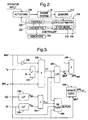
- FIG 2 is a general block diagram of the system 10 of Figure 1, including an engine 210, sensors 212, and the Controller 214 which controls the engine operation.
- the Controller 214 additionally carries out a sequence of state estimator operations for estimating pressures of interest at certain of the nodes of Figure 1, and for determining mass flow rates through certain of the flow branches of Figure 1.
- a state model 218 for modeling such pressures and flows is included with the state estimator 216.
- the flow outputs are used to estimate the intake mass air flow MAF int for the purpose of estimating the barometric pressure P AT , which in turn, is used in conjunction with the flow and pressure estimators to schedule engine fueling and various other controls, as indicated by the block 220.
- the pressure and flow information may also be used in various diagnostic procedures 222 for diagnosing certain engine control systems.
- the controls 220 issue control signals to drive various engine system control actuators 226, such as fuel injectors 87, idle air bypass valve 60, EGR valve 41, etc. in accordance with generally available control strategies. Manual operator inputs may further be applied to such actuators, as is generally understood in the art.
- the diagnostics 222 interact with the controls according to standard control and diagnostic procedures and may provide diagnostic information to various conventional indicators 224, such lamps or chimes.
- the Controller 214 may take the form of a conventional single-chip micro-controller including such conventional elements as a central processing unit, an input-output unit, and memory devices including random access memory RAM devices, read only memory ROM devices and other standard elements.
- Figures 3-5 depict a block diagram of the barometric pressure estimation portion of the control, according to the first embodiment where a mass air flow sensor 100 is used to measure the intake mass air flow MAF int .
- the system inputs include the manifold absolute pressure MAP, the intake or ambient air temperature T AT , the intake mass air flow MAF int , the idle air control position IAC, and the throttle position TP.
- the elements 230-234 combine the flow related terms (FT) as a function of inverse MAP, T AT , MAF int , and the universal gas constant for air R.
- FT flow related terms
- the inverter element 230 inverts the MAP signal
- the square-root element 232 forms the quantity (R * T AT ) 1 ⁇ 2
- the multiplier element forms the quantity [MAF int * (R * T AT ) 1 ⁇ 2 ]/ MAP.
- the elements 236-240 form the effective intake area term A int as defined above.
- the look-up table (LUT) element 236 provides the effective idle bypass area A iac as a function of the IAC input
- the look-up table (LUT) element 238 provides the effective throttle area A thr as a function of the TP input
- the adder element forms the total effective intake area A int as the sum of A thr and A iac .
- the flow term FT and the total effective intake area A int are provided as inputs to the 3D look-up table (LUT) element 242, which effectuates the non-linear ⁇ -function described above.
- the output of element 242 is the pressure ratio P AT /MAP.
- the multiplier element 244 forms the product MAP[P AT /MAP] to provide the estimate of barometric pressure, designated in Figure 3 as BPE new .
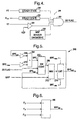
- the element 246, described below in reference to Figure 4 determines the status of a Steady State flag, and the element 248, described below in reference to Figure 5, provides update logic to update the barometric pressure output value BPE out .
- the status of the Steady State flag is determined based on four inputs: flow parameter FT, intake area A int , throttle position TP, and a MAP sensor diagnostic 256.
- the blocks 250-258 check the condition of the various inputs, and provide inputs to AND-gate 260. If the various conditions defined by blocks 250-258 are satisfied, the SS Flag output of AND-gate 260 provides an indication to Update Logic element 248 that BPE new is valid and may be used to update BPE out . If any of the conditions are not satisfied, the SS Flag output of AND-gate 260 indicates to Update Logic element 248 that BPE new should not be used to update BPE out .
- the blocks 250 and 252 determine if the respective input values FT and A int are in an apparent steady state condition. This may be determined by filtering the input value, and comparing the filtered version to the current input value to determine if the input is changing by more than a predefined rate. If a steady state condition is detected (i.e., input rate of change less than a predefined rate) the respective elements 250, 252 provide a logic one output to AND-gate 260.
- the compare element 254 compares the TP input to a reference value (for example, corresponding to 30% open throttle position) and provides a logic one input to AND-gate 260 if TP exceeds the reference value. Thus, if TP is less than the reference value, BPE new is not used to update BPE out .
- the MAP sensor diagnostic 256 develops a flag output based on a diagnostic evaluation of the MAP sensor 24, and supplies a logic one input to AND-gate 260 if proper operation of the MAP sensor 24 is confirmed.
- the Update Logic element 248 receives BPE new , the SS Flag and MAP as inputs, and provides BPE out , as an output.
- the element 262 is a two input switch controlled by the status of the SS Flag. When the SS Flag is set, indicating that BPE new is valid and may be used to update BPE out , the switch allows the output of adder element 264 to appear on line 266. When the SS Flag is cleared, indicating that BPE new should not be used to update BPE out , the switch applies BPE out to line 266.
- the adder element 264 along with gain elements 268 and 270, form an updated or filtered version of the pressure estimate (referred to in Figure 5 as BPE f ) in which a specified fraction of BPE new is added to a specified fraction of BPE out .
- the element 272 compares the output of switch 262 to the MAP value, and supplies the larger of the two as an input to limit element 274; this recognizes that the actual barometric pressure is always at least as great as the intake manifold pressure MAP.
- the limit block 274 limits the output of block 272 to a range of values bounded by maximum and minimum reference values BPE max and BPE min , the output of block 274 forming the output estimate BPE out .
- the diagram of Figure 6 generally depicts a mechanization according to the second embodiment of this invention where the intake mass air flow MAF int is determined not by a mass air flow sensor, but by a combination of various estimated flows within the engine system 10. This, of course, eliminates the requirement of a mass air flow sensor, and it particularly useful in systems that utilize a speed-density technique to schedule engine fueling.
- non-intake flows include the purge valve flow (designated in Figure 1 as F 10 ) and the EGR valve flow (designated in Figure 1 as F 8 ).
- Flows F 16 and F 9 attributable to the pneumatic brake boost system and the PCV valve 51 are neglected due to their relatively small magnitudes.
- the intake system flow MAF int is formed in adder element in accordance with the engine flow F 5 less the EGR flow F 8 and the purge valve flow F 10 .
- the flows F 5 , F 8 and F 10 are determined in accordance with a state estimator technique in which the various flow rates identified in Figure 1 are estimated based on corresponding pressure ratios (including the barometric pressure estimate described above), the flow rates are used to determine net flows in the various nodes identified in Figure 1, the net flows are used to estimate the pressure change at the various nodes, and the estimated pressure changes are integrated to provide pressure estimates for the next computation cycle.
- the flow and pressure information is then applied in general engine system control and diagnostic operations.
- Figures 7-9 represent computer program instructions executed by the Controller 214 of Figure 2 in carrying out a control in accordance with the second embodiment of this invention in which the intake airflow is estimated based on related airflows determined by a state estimator.
- the control is greatly simplified when carried out in accordance with the first embodiment, where the intake airflow is measured by mass air flow sensor 100, and the state estimator is not required.
- the block 306 is then executed to carry out any required general initialization operations including such well-known startup operations as operations to clear memory locations, to transfer data and program instructions from ROM devices to RAM devices, and to set pointers, counters and constants to initial values.
- Numerous time and event based interrupts are next enabled at block 310 to occur following certain time intervals, or following certain engine system events such as cylinder top dead center events whereby interrupt service operations are carried out following such interrupts to provide for synchronous and asynchronous engine system control, diagnostic and maintenance operations.
- Background operations are then carried out at block 312 including general, low priority maintenance and diagnostic operations, including operations to diagnose the engine system through application of the pneumatic state estimation information provided by the state estimator 216 of Figure 2.
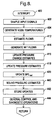
- Figure 8 depicts a series of operations for servicing a timer or event based interrupt 400 enabled at block 310 of Figure 7. Following each such interrupt occurrence, after temporarily suspending any ongoing controller operations of lower priority in a pre-established priority hierarchy, the block 402 samples input signals including MAP, TP, RPM, and FP of Figure 1. Temperature estimation operations are next carried out at block 404, including operations for directly measuring or estimating gas temperature at various nodes within the engine system 10, including at nodes N1 , N3 , N5 , N6 , and N7 of Figure 1. For example, the temperature estimation operations described in the disclosure of copending U.S. patent application serial number 08/862,074, filed May 22, 1997, assigned to the assignee of this application and hereby incorporated herein by reference, may be carried out at block 404 with respect to such nodes.
- the flow estimates from block 412 are combined to determine the net flow of each node of interest within the engine system 10.
- f net / ec (t) f rol (t) - f prg (t) - f vnt (t) .
- the pressure estimates are subject to certain instabilities, for example due to the relatively granular iteration rate h, which is selected as the highest iteration rate that can be tolerated within the throughput constraints and competing priorities the Controller 214 so as to provide as much estimation stability as possible.
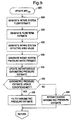
- the barometric pressure is then estimated at block 420 as described above in reference to the block diagram of Figures 3-6, using the determined flows f prg (t) , f egr (t) and f eng (t) is to estimate the intake mass air flow MAF int .
- Block 428 determines the intake effective area A int as described above in reference to Figure 3, using the 2D lookup tables 236 and 238, and combining the throttle and idle air control values.
- Block 430 determines the pressure ratio P AT /MAP as a 3D lookup table function of FT and A int , and block 432 determines the instantaneous barometric pressure estimate BPE new based on the product of P AT /MAP and MAP. If the steady state flag conditions described above in reference to Figure 4 are satisfied, as determined at block 434, the block 436 is executed to compute the filtered term BPE f based on BPE new and BPE out . Otherwise, the current value of BPE out is retained, as indicated at block 438.
- the block 440 is then executed to suitably bound the pressure estimates.
- the estimates are bounded as follows:
- the block 442 is then executed to store the updated temperature, pressure and flow values are then stored in a memory of the Controller 214 as the most recent temperature, pressure and flow information for use in engine system control and diagnostic operations, and for use in the next iteration of the interrupt routine during which such stored values are updated in the manner described for steps 402-420. Conventional engine control and diagnostic operations are then carried out at block 444.
- Such operations include, for example, operations to determine and provide for issuance of a fuel injector drive command to fuel injector 87 as a function of the estimated gas flow rate along flow branch F 5 , an idle air command to bypass valve 60 as a function of manual operator input and estimated gas flow into the intake manifold via flow path F 4 , a canister purge valve position command for the canister purge valve 53 as a function of estimated gas flow rate along flow branch F 10 , an EGR position command to EGR valve 41 as a function of gas flow along flow branch F 8 , etc.
- Conventional diagnostic operations such as operations to diagnose operability of elements 19, 60, 41, 67, and 92 may further be carried out at the step 426 using the temperature, pressure and flow information determined through the operations of Figure 8.
- this invention provides an engine control with a model-based estimation of barometric pressure that, in a first embodiment eliminates the necessity of a barometric pressure sensor, and in a second embodiment eliminates the necessity of both a barometric pressure sensor and a mass air flow sensor.
- the model-based nature of the control significantly simplifies the calibration effort, as the required lookup table may be calibrated at any altitude.
- the mass airflows needed to estimate the intake airflow MAF int according to the second embodiment of this invention may be determined in a different manner than described herein. Accordingly, it will be understood that systems and controls incorporating these and other modifications may fall within the scope of this invention, which is defined by the appended claims.
Landscapes
- Engineering & Computer Science (AREA)
- Chemical & Material Sciences (AREA)
- Combustion & Propulsion (AREA)
- Mechanical Engineering (AREA)
- General Engineering & Computer Science (AREA)
- Combined Controls Of Internal Combustion Engines (AREA)
- Electrical Control Of Air Or Fuel Supplied To Internal-Combustion Engine (AREA)
Applications Claiming Priority (2)
| Application Number | Priority Date | Filing Date | Title |
|---|---|---|---|
| US174234 | 1998-10-16 | ||
| US09/174,234 US6016460A (en) | 1998-10-16 | 1998-10-16 | Internal combustion engine control with model-based barometric pressure estimator |
Publications (2)
| Publication Number | Publication Date |
|---|---|
| EP0994246A2 true EP0994246A2 (de) | 2000-04-19 |
| EP0994246A3 EP0994246A3 (de) | 2002-02-13 |
Family
ID=22635382
Family Applications (1)
| Application Number | Title | Priority Date | Filing Date |
|---|---|---|---|
| EP99203062A Withdrawn EP0994246A3 (de) | 1998-10-16 | 1999-09-20 | Brennkraftmaschinensteuerung mit modelbasiertem barometrischen Druckabschätzer |
Country Status (2)
| Country | Link |
|---|---|
| US (1) | US6016460A (de) |
| EP (1) | EP0994246A3 (de) |
Cited By (4)
| Publication number | Priority date | Publication date | Assignee | Title |
|---|---|---|---|---|
| FR2813100A1 (fr) * | 2000-08-16 | 2002-02-22 | Bosch Gmbh Robert | Procede et dispositif pour la mise en oeuvre d'un moteur a combustion interne |
| CN103748588A (zh) * | 2011-08-22 | 2014-04-23 | 罗伯特·博世有限公司 | 用于建立模型的方法 |
| US9261432B2 (en) | 2013-07-25 | 2016-02-16 | Ford Global Technologies, Llc | Barometric pressure inference based on tire pressure |
| AT523182B1 (de) * | 2019-12-06 | 2021-06-15 | Avl List Gmbh | Brennkraftmaschine mit einem einlasstrakt |
Families Citing this family (36)
| Publication number | Priority date | Publication date | Assignee | Title |
|---|---|---|---|---|
| US6119512A (en) * | 1999-01-15 | 2000-09-19 | Daimlerchrysler Corporation | Method of determining a fuel tank vapor flow rate |
| US6430515B1 (en) * | 1999-09-20 | 2002-08-06 | Daimlerchrysler Corporation | Method of determining barometric pressure for use in an internal combustion engine |
| US6305350B1 (en) * | 2000-06-20 | 2001-10-23 | General Motors Corporation | Engine speed control |
| US6390055B1 (en) | 2000-08-29 | 2002-05-21 | Ford Global Technologies, Inc. | Engine mode control |
| US6366847B1 (en) | 2000-08-29 | 2002-04-02 | Ford Global Technologies, Inc. | Method of estimating barometric pressure in an engine control system |
| DE10065122A1 (de) * | 2000-12-28 | 2002-08-14 | Bosch Gmbh Robert | Verfahren zur Erfassung von Stand der Technik Massenströmen zum Saugrohr einer Brennkraftmaschine |
| US6658364B2 (en) * | 2001-01-12 | 2003-12-02 | Delphi Technologies, Inc. | Method of estimating gas pressure in an engine exhaust manifold |
| DE10115750B4 (de) * | 2001-03-20 | 2017-05-24 | Robert Bosch Gmbh | Verfahren und Vorrichtung zur Steuerung und/oder Diagnose eines einen Massenstrom beeinflussenden Steuersystems |
| US6459985B1 (en) * | 2001-06-19 | 2002-10-01 | Ford Global Technologies, Inc. | Flow measurement system providing indication of atmospheric (barometric) pressure |
| US6435170B1 (en) | 2001-08-01 | 2002-08-20 | Dana Corporation | Crankcase bypass system with oil scavenging device |
| FR2853012B1 (fr) * | 2003-03-26 | 2006-06-16 | Siemens Vdo Automotive | Mesure de la pression ambiante dans un moteur turbocompresse |
| US7024301B1 (en) | 2005-01-14 | 2006-04-04 | Delphi Technologies, Inc. | Method and apparatus to control fuel metering in an internal combustion engine |
| CN100441852C (zh) * | 2005-03-31 | 2008-12-10 | 丰田自动车株式会社 | 内燃机控制装置 |
| US7117078B1 (en) | 2005-04-22 | 2006-10-03 | Gm Global Technology Operations, Inc. | Intake oxygen estimator for internal combustion engine |
| US7433775B2 (en) * | 2006-11-17 | 2008-10-07 | Gm Global Technology Operations, Inc. | Engine torque control at high pressure ratio |
| US7565236B2 (en) * | 2007-07-20 | 2009-07-21 | Gm Global Technology Operations, Inc. | Airflow estimation method and apparatus for internal combustion engine |
| US7631551B2 (en) * | 2007-07-27 | 2009-12-15 | Gm Global Technology Operations, Inc. | Adaptive barometric pressure estimation in which an internal combustion engine is located |
| US20090050116A1 (en) * | 2007-08-21 | 2009-02-26 | Cummings Craig D | Fluid ionizing device for internal combustion engines |
| US20090049897A1 (en) * | 2007-08-24 | 2009-02-26 | Olin Peter M | Method for on-line adaptation of engine volumetric efficiency using a mass air flow sensor |
| US7912623B2 (en) * | 2007-09-25 | 2011-03-22 | Denso Corporation | Engine control system designed to manage schedule of engine control tasks |
| DE102008025549B4 (de) * | 2008-05-28 | 2010-07-01 | Continental Automotive Gmbh | Verfahren und Vorrichtung zum Betreiben einer Brennkraftmaschine |
| CN102308075B (zh) | 2009-02-06 | 2014-11-26 | 本田技研工业株式会社 | 大气压估计装置 |
| CN102317606B (zh) | 2009-02-17 | 2014-04-02 | 本田技研工业株式会社 | 内燃机的汽缸吸入空气量计算装置 |
| JP4862083B2 (ja) | 2010-01-12 | 2012-01-25 | 本田技研工業株式会社 | 内燃機関の気筒吸入空気量算出装置 |
| DE102010052644A1 (de) * | 2010-11-29 | 2012-05-31 | Audi Ag | Verfahren zum Betreiben einer Brennkraftmaschine, Steuerelement, Brennkraftmaschine |
| US9297319B2 (en) * | 2010-12-31 | 2016-03-29 | GM Global Technology Operations LLC | Control of EGR, fresh mass air flow, and boost pressure for internal combustion engines |
| US20140318500A1 (en) * | 2011-10-26 | 2014-10-30 | Toyota Jidosha Kabushiki Kaisha | Fuel property determination system for vehicle |
| US9359923B2 (en) | 2012-10-25 | 2016-06-07 | Ford Global Technologies, Llc | Method and system for fuel vapor management |
| US9347368B2 (en) | 2012-10-25 | 2016-05-24 | Ford Global Technologies, Llc | Method and system for fuel vapor management |
| US9435283B2 (en) | 2013-12-03 | 2016-09-06 | Ford Global Technologies, Llc | Method for inferring barometric pressure at low throttle angles |
| US9810171B2 (en) | 2013-12-03 | 2017-11-07 | Ford Global Technologies, Llc | Method for determining an offset of a manifold pressure sensor |
| JP6156429B2 (ja) * | 2014-05-26 | 2017-07-05 | トヨタ自動車株式会社 | 内燃機関の制御装置 |
| US9644543B2 (en) * | 2015-02-17 | 2017-05-09 | GM Global Technology Operations LLC | Prediction of intake manifold pressure in an engine system |
| CN105785791B (zh) * | 2016-02-26 | 2018-05-18 | 南京航空航天大学 | 一种超声速状态下机载推进系统的建模方法 |
| JP6755781B2 (ja) * | 2016-11-22 | 2020-09-16 | 愛三工業株式会社 | 吸気システム |
| US11085382B2 (en) * | 2018-03-02 | 2021-08-10 | Ford Global Technologies, Llc | Evaporative emission control system and method |
Family Cites Families (9)
| Publication number | Priority date | Publication date | Assignee | Title |
|---|---|---|---|---|
| DE3238190C2 (de) * | 1982-10-15 | 1996-02-22 | Bosch Gmbh Robert | Elektronisches System zum Steuern bzw. Regeln von Betriebskenngrößen einer Brennkraftmaschine |
| DE68904437D1 (de) * | 1988-01-29 | 1993-03-04 | Hitachi Ltd | Steuerung fuer motor-kraftstoffeinspritzung. |
| US4926335A (en) * | 1988-07-25 | 1990-05-15 | General Motors Corporation | Determining barometric pressure using a manifold pressure sensor |
| US5136517A (en) * | 1990-09-12 | 1992-08-04 | Ford Motor Company | Method and apparatus for inferring barometric pressure surrounding an internal combustion engine |
| US5070846A (en) * | 1990-11-26 | 1991-12-10 | General Motors Corporation | Method for estimating and correcting bias errors in a software air meter |
| JP2625048B2 (ja) * | 1991-06-10 | 1997-06-25 | 三菱電機株式会社 | 排ガス還流装置の故障検出装置 |
| US5481462A (en) * | 1992-10-15 | 1996-01-02 | Toyota Jidosha Kabushiki Kaisha | Apparatus for determining an altitude condition of an automotive vehicle |
| JP3354304B2 (ja) * | 1994-07-29 | 2002-12-09 | 本田技研工業株式会社 | 内燃機関の燃料噴射制御装置 |
| JP3154038B2 (ja) * | 1995-01-06 | 2001-04-09 | 株式会社ユニシアジェックス | 内燃機関の吸気圧力推定装置及び燃料供給装置 |
-
1998
- 1998-10-16 US US09/174,234 patent/US6016460A/en not_active Expired - Fee Related
-
1999
- 1999-09-20 EP EP99203062A patent/EP0994246A3/de not_active Withdrawn
Cited By (5)
| Publication number | Priority date | Publication date | Assignee | Title |
|---|---|---|---|---|
| FR2813100A1 (fr) * | 2000-08-16 | 2002-02-22 | Bosch Gmbh Robert | Procede et dispositif pour la mise en oeuvre d'un moteur a combustion interne |
| CN103748588A (zh) * | 2011-08-22 | 2014-04-23 | 罗伯特·博世有限公司 | 用于建立模型的方法 |
| US9261432B2 (en) | 2013-07-25 | 2016-02-16 | Ford Global Technologies, Llc | Barometric pressure inference based on tire pressure |
| AT523182B1 (de) * | 2019-12-06 | 2021-06-15 | Avl List Gmbh | Brennkraftmaschine mit einem einlasstrakt |
| AT523182A1 (de) * | 2019-12-06 | 2021-06-15 | Avl List Gmbh | Brennkraftmaschine mit einem einlasstrakt |
Also Published As
| Publication number | Publication date |
|---|---|
| US6016460A (en) | 2000-01-18 |
| EP0994246A3 (de) | 2002-02-13 |
Similar Documents
| Publication | Publication Date | Title |
|---|---|---|
| US6016460A (en) | Internal combustion engine control with model-based barometric pressure estimator | |
| EP0881374B1 (de) | Pneumatischer Zustandschätzer für Brennkraftmaschine | |
| EP0845586B1 (de) | Verfahren zur Bestimmung von pneumatischen Zuständen in einem Brennkraftmaschinensystem | |
| US7748217B2 (en) | System and method for modeling of turbo-charged engines and indirect measurement of turbine and waste-gate flow and turbine efficiency | |
| US7438061B2 (en) | Method and apparatus for estimating exhaust pressure of an internal combustion engine | |
| EP0845587A2 (de) | Durchflussbestimmung in einer Einlassöffnung einer Brennkraftmaschine | |
| EP0478120B1 (de) | Verfahren und Vorrichtung zur Ableitung des den Innenverbrennungsmotor umgebenden atmosphärischen Druckes | |
| EP2003315B1 (de) | Steuerung der Kraftstoffeinspritzung für einen Verbrennungsmotor | |
| EP0476811B1 (de) | Verfahren und Vorrichtung zum Steuern eines Verbrennungsmotors | |
| KR20050040808A (ko) | 내연 엔진에서의 흡입 가스 온도의 추정 장치 및 방법 | |
| US6293267B1 (en) | Flow-based control method for an engine control valve | |
| US20200132002A1 (en) | Throttle controller and throttle controlling method | |
| US20040045526A1 (en) | Method and system for controlling partial pressure of air in an intake manifold of an engine | |
| JPH07293358A (ja) | エバポパージシステムの故障診断方法 | |
| JPH11166455A (ja) | 内燃機関の空燃比制御装置 | |
| US7004156B2 (en) | Method for determining intake port flow in an internal combustion engine | |
| JPH1061481A (ja) | 外部排気ガス再循環を有する内燃機関の負荷信号の決定方法 | |
| CN110361198A (zh) | 车辆蒸发排放系统脱附流量故障检测装置、方法及车辆 | |
| US7957886B2 (en) | Apparatus for and method of controlling internal combustion engine equipped with turbocharger | |
| US11047319B2 (en) | Method and system for calculating fuel injection amount of fuel vapor dual purge system | |
| DE102016203333A1 (de) | Emissionsabschätzungsvorrichtung für maschine mit interner verbrennung | |
| US20120298080A1 (en) | Method for operating an internal combustion engine, control element, internal combustion engine | |
| JP4248209B2 (ja) | 内燃機関の蒸発燃料処理 | |
| EP1568873B1 (de) | Steuerungsvorrichtung für eine Brennkraftmaschine | |
| JPS59192858A (ja) | キヤニスタパ−ジ制御装置 |
Legal Events
| Date | Code | Title | Description |
|---|---|---|---|
| PUAI | Public reference made under article 153(3) epc to a published international application that has entered the european phase |
Free format text: ORIGINAL CODE: 0009012 |
|
| AK | Designated contracting states |
Kind code of ref document: A2 Designated state(s): AT BE CH CY DE DK ES FI FR GB GR IE IT LI LU MC NL PT SE Kind code of ref document: A2 Designated state(s): DE FR GB |
|
| AX | Request for extension of the european patent |
Free format text: AL;LT;LV;MK;RO;SI |
|
| PUAL | Search report despatched |
Free format text: ORIGINAL CODE: 0009013 |
|
| RIC1 | Information provided on ipc code assigned before grant |
Free format text: 7F 02D 41/32 A, 7F 02D 41/18 B |
|
| AK | Designated contracting states |
Kind code of ref document: A3 Designated state(s): AT BE CH CY DE DK ES FI FR GB GR IE IT LI LU MC NL PT SE |
|
| AX | Request for extension of the european patent |
Free format text: AL;LT;LV;MK;RO;SI |
|
| 17P | Request for examination filed |
Effective date: 20020813 |
|
| AKX | Designation fees paid |
Free format text: DE FR GB |
|
| 17Q | First examination report despatched |
Effective date: 20030509 |
|
| STAA | Information on the status of an ep patent application or granted ep patent |
Free format text: STATUS: THE APPLICATION IS DEEMED TO BE WITHDRAWN |
|
| 18D | Application deemed to be withdrawn |
Effective date: 20030920 |