EP0997337A2 - Kraftstoff-Einfüllstutzen, insbesondere für ein Kraftfahrzeug - Google Patents
Kraftstoff-Einfüllstutzen, insbesondere für ein Kraftfahrzeug Download PDFInfo
- Publication number
- EP0997337A2 EP0997337A2 EP99121411A EP99121411A EP0997337A2 EP 0997337 A2 EP0997337 A2 EP 0997337A2 EP 99121411 A EP99121411 A EP 99121411A EP 99121411 A EP99121411 A EP 99121411A EP 0997337 A2 EP0997337 A2 EP 0997337A2
- Authority
- EP
- European Patent Office
- Prior art keywords
- cap
- filler
- cylinder
- locking member
- control portion
- Prior art date
- Legal status (The legal status is an assumption and is not a legal conclusion. Google has not performed a legal analysis and makes no representation as to the accuracy of the status listed.)
- Withdrawn
Links
- 239000000945 filler Substances 0.000 title claims abstract description 69
- 239000000446 fuel Substances 0.000 title claims abstract description 9
- 230000002441 reversible effect Effects 0.000 claims abstract description 13
- 230000002093 peripheral effect Effects 0.000 claims description 5
- 238000007789 sealing Methods 0.000 claims description 5
- 230000005489 elastic deformation Effects 0.000 claims description 2
- 230000004075 alteration Effects 0.000 description 1
- 230000000712 assembly Effects 0.000 description 1
- 238000000429 assembly Methods 0.000 description 1
- 239000002828 fuel tank Substances 0.000 description 1
- 239000002861 polymer material Substances 0.000 description 1
Images

Classifications
-
- B—PERFORMING OPERATIONS; TRANSPORTING
- B60—VEHICLES IN GENERAL
- B60K—ARRANGEMENT OR MOUNTING OF PROPULSION UNITS OR OF TRANSMISSIONS IN VEHICLES; ARRANGEMENT OR MOUNTING OF PLURAL DIVERSE PRIME-MOVERS IN VEHICLES; AUXILIARY DRIVES FOR VEHICLES; INSTRUMENTATION OR DASHBOARDS FOR VEHICLES; ARRANGEMENTS IN CONNECTION WITH COOLING, AIR INTAKE, GAS EXHAUST OR FUEL SUPPLY OF PROPULSION UNITS IN VEHICLES
- B60K15/00—Arrangement in connection with fuel supply of combustion engines or other fuel consuming energy converters, e.g. fuel cells; Mounting or construction of fuel tanks
- B60K15/03—Fuel tanks
- B60K15/04—Tank inlets
- B60K15/0406—Filler caps for fuel tanks
- B60K15/0409—Provided with a lock
-
- Y—GENERAL TAGGING OF NEW TECHNOLOGICAL DEVELOPMENTS; GENERAL TAGGING OF CROSS-SECTIONAL TECHNOLOGIES SPANNING OVER SEVERAL SECTIONS OF THE IPC; TECHNICAL SUBJECTS COVERED BY FORMER USPC CROSS-REFERENCE ART COLLECTIONS [XRACs] AND DIGESTS
- Y10—TECHNICAL SUBJECTS COVERED BY FORMER USPC
- Y10T—TECHNICAL SUBJECTS COVERED BY FORMER US CLASSIFICATION
- Y10T70/00—Locks
- Y10T70/50—Special application
- Y10T70/5093—For closures
- Y10T70/554—Cover, lid, cap, encasing shield
- Y10T70/5562—Removable
- Y10T70/5571—Freely movable when locked
-
- Y—GENERAL TAGGING OF NEW TECHNOLOGICAL DEVELOPMENTS; GENERAL TAGGING OF CROSS-SECTIONAL TECHNOLOGIES SPANNING OVER SEVERAL SECTIONS OF THE IPC; TECHNICAL SUBJECTS COVERED BY FORMER USPC CROSS-REFERENCE ART COLLECTIONS [XRACs] AND DIGESTS
- Y10—TECHNICAL SUBJECTS COVERED BY FORMER USPC
- Y10T—TECHNICAL SUBJECTS COVERED BY FORMER US CLASSIFICATION
- Y10T70/00—Locks
- Y10T70/50—Special application
- Y10T70/5093—For closures
- Y10T70/554—Cover, lid, cap, encasing shield
- Y10T70/5562—Removable
- Y10T70/5575—Directly seating
- Y10T70/558—Cover-carried lock
- Y10T70/5589—Latching bolt
-
- Y—GENERAL TAGGING OF NEW TECHNOLOGICAL DEVELOPMENTS; GENERAL TAGGING OF CROSS-SECTIONAL TECHNOLOGIES SPANNING OVER SEVERAL SECTIONS OF THE IPC; TECHNICAL SUBJECTS COVERED BY FORMER USPC CROSS-REFERENCE ART COLLECTIONS [XRACs] AND DIGESTS
- Y10—TECHNICAL SUBJECTS COVERED BY FORMER USPC
- Y10T—TECHNICAL SUBJECTS COVERED BY FORMER US CLASSIFICATION
- Y10T70/00—Locks
- Y10T70/70—Operating mechanism
- Y10T70/7441—Key
- Y10T70/7768—Key-removal preventing
Definitions
- the present invention relates to a fuel filler assembly, in particular for a motor vehicle.
- Vehicle fuel filler assemblies are known wherein the cap, once screwed onto the filler, is locked by a key-operated locking device, e.g. using the ignition key of the vehicle itself, and the key can be withdrawn from the lock cylinder (inside the cap) even when the cap is not fitted or is fitted improperly to the filler, so that the danger exists of the vehicle being started up with a badly fitted or no cap at all, thus resulting in possible leakage of fuel vapours or even actual fuel.
- a key-operated locking device e.g. using the ignition key of the vehicle itself
- a fuel filler assembly in particular for a motor vehicle, comprising a filler and a cap for closing a mouth of said filler; said cap being provided internally with a cylinder rotated by means of an operating key; characterized by also comprising reversible locking means for reversibly locking relative rotation of said cylinder with respect to said cap; and actuating means for selectively moving said reversible locking means into a first operating position when said cap is detached from said filler, and a second operating position when said cap is fitted closing the filler : in said first operating position, said reversible locking means securing said cylinder angularly to said cap to prevent said relative rotation of the cylinder with respect to the cap and, hence, withdrawal of the operating key from the cylinder; and, in said second operating position, said reversible locking means permitting relative rotation of the cylinder with respect to the cap to permit withdrawal of the operating key from the cylinder.
- the cylinder therefore only rotates inside the cap when set to the second operating position by the actuating means of the filler, which in turn only occurs when the cap is fitted correctly closing the filler. Conversely, when the cap is detached from the filler, the cylinder is secured angularly to the cap and prevented from being rotated into the position permitting withdrawal of the key.
- the filler assembly according to the invention is also cheap and easy to produce, and may be applied to various vehicles with no particularly complex alterations required.
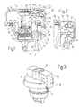
- number 1 indicates as a whole a motor vehicle filler assembly comprising a tubular filler 2 connected, in known manner not shown for the sake of simplicity, to a fuel tank and defined at one end by a circular mouth 3 for receiving a cap 4 for closing filler 2.
- Cap 4 is fitted to filler 2 in known manner and comprises a known key-operated locking device not described in detail for the sake of simplicity. More specifically, cap 4 is provided internally with a cylinder 5 housed for rotation inside a respective cylindrical seat 6 defined by a lateral wall 7; cylinder 5 is rotated inside cylindrical seat 6 by means of an operating key inserted inside a slot 8 in cylinder 5; and cap 4 also has an annular chamber 9 extending about and radially outwards of cylindrical seat 6.
- filler assembly 1 comprises reversible locking means 10 for reversibly locking relative rotation of cylinder 5 with respect to cap 4.
- reversible locking means 10 comprise a locking member 11 fitted movably inside annular chamber 9 of cap 4 : in the example shown, locking member 11 comprises a rocker-arm body 12 made, for example, of substantially rigid polymer material and hinged to cap 4 at at least one fulcrum 13 by, for example, two pins 14 ( Figure 5) inserted inside respective supports (not shown for the sake of simplicity) on cap 4; opposite arms of rocker-arm body 12, located on opposite sides of fulcrum 13, respectively define a lock tooth 15 and a control portion 16, which is housed in sliding manner inside a guide 17 formed at a peripheral edge 18 of cap 4 and more specifically inside an eccentric projecting portion 19 of cap 4; and control portion 16 of locking member 11 is connected in one piece to rocker-arm body 12 by a narrow section 20, which acts as a virtual hinge permitting predetermined elastic deformation of control portion 16 with respect to rocker-
- Lock tooth 15 of locking member 11 extends radially through a through opening 23 formed in lateral wall 7 defining cylindrical seat 6 of cylinder 5 and separating cylindrical seat 6 from annular chamber 9.
- Cylinder 5 comprises a seat 24 defined, in the example shown, by a slot of predetermined size formed in a circumferential collar 25, of predetermined height, of cylinder 5. As explained later on, seat 24 provides for receiving lock tooth 15 of locking member 11.
- Locking member 11 also comprises elastic means 26 for exerting a predetermined action on and for maintaining locking member 11 in a predetermined position. More specifically, elastic means 26 comprise a fork-shaped spring made of bent wire, a first arm 27 of which is secured integrally to locking member 11, and a second arm 28 of which rests on an inner surface 29 of cap 4, e.g. a wall of annular chamber 9.
- Filler 2 comprises an actuating member 31 defined, in the non-limiting embodiment shown in Figures 1 and 2, by a stop surface 32 of an annular collar 33 located radially outwards, and a predetermined distance from an end edge 34, of mouth 3.
- Filler assembly 1 also comprises, in substantially known manner, face and/or radial sealing means 35 between cap 4 and filler 2.
- sealing means 35 may comprise a face sealing ring 36, e.g. housed in a circumferential seat on cap 4 and which rests on end edge 34 of mouth 3, and/or a radial sealing ring 37, e.g. housed in a respective circumferential seat formed on a lateral outer surface of filler 2, close to mouth 3, and which cooperates with an inner edge 38 of cap 4.
- locking means 10 are in an operating position 10a wherein locking member 11 is maintained by spring 26 in a stop position 11a with lock tooth 15 engaging seat 24 of cylinder 5; and control portion 16 of locking member 11 is of such an extension that a free end 39 of the control portion projects a given amount from guide 17.
- locking means 10 prevent relative rotation of cylinder 5 with respect to cap 4, and in particular rotation of cylinder 5 into the position enabling withdrawal of the operating key, which therefore cannot be extracted.
- actuating member 31 of filler 2 pushes control portion 16 of locking member 11 projecting from guide 17 so as to rotate locking member 11 about fulcrum 13 and, in opposition to the elastic reaction of spring 26, into a rest position lib wherein lock tooth 15 is withdrawn from seat 24 of cylinder 5 and moved into a position beneath circumferential collar 25 of cylinder 5.
- reversible locking means 10 therefore assume an operating position 10b permitting relative rotation of cylinder 5 with respect to cap 4, and in particular rotation of cylinder 5 into the position enabling withdrawal of the operating key.
- Filler assembly 1a is identical to filler assembly 1 described above, except for control portion 16 of locking member 11, which in this case is again housed in sliding manner inside guide 17 of cap 4, but is of such an extension as to be housed entirely inside guide 17 even when locking member 11 is in stop position 11a ( Figure 6).
- actuating member 31 of filler 2 again comprises an annular collar 33 located radially outwards, and a predetermined distance from an end edge 34, of mouth 3, but also comprises a projection 40 projecting from an outer peripheral edge 41 of annular collar 33 and so sized as to be insertable inside guide 17 of cap 4 to push the free end 39 of control portion 16 of locking member 11 when cap 4 is fitted closing mouth 3 of filler 2 ( Figure 7).
Landscapes
- Engineering & Computer Science (AREA)
- Life Sciences & Earth Sciences (AREA)
- Sustainable Development (AREA)
- Sustainable Energy (AREA)
- Chemical & Material Sciences (AREA)
- Combustion & Propulsion (AREA)
- Transportation (AREA)
- Mechanical Engineering (AREA)
- Cooling, Air Intake And Gas Exhaust, And Fuel Tank Arrangements In Propulsion Units (AREA)
- Lock And Its Accessories (AREA)
- Catalysts (AREA)
Applications Claiming Priority (2)
| Application Number | Priority Date | Filing Date | Title |
|---|---|---|---|
| ITTO980914 | 1998-10-28 | ||
| IT1998TO000914A IT1305144B1 (it) | 1998-10-28 | 1998-10-28 | Gruppo bocchettone per il rifornimento di carburante, in particolareper un veicolo a motore. |
Publications (2)
| Publication Number | Publication Date |
|---|---|
| EP0997337A2 true EP0997337A2 (de) | 2000-05-03 |
| EP0997337A3 EP0997337A3 (de) | 2000-10-18 |
Family
ID=11417143
Family Applications (1)
| Application Number | Title | Priority Date | Filing Date |
|---|---|---|---|
| EP99121411A Withdrawn EP0997337A3 (de) | 1998-10-28 | 1999-10-27 | Kraftstoff-Einfüllstutzen, insbesondere für ein Kraftfahrzeug |
Country Status (3)
| Country | Link |
|---|---|
| US (1) | US6220064B1 (de) |
| EP (1) | EP0997337A3 (de) |
| IT (1) | IT1305144B1 (de) |
Cited By (1)
| Publication number | Priority date | Publication date | Assignee | Title |
|---|---|---|---|---|
| EP1264725A1 (de) * | 2001-06-09 | 2002-12-11 | Ti Group Automotive Systems (Fuldabrück) GmbH | Verschluss für einen Tank eines Kraftfahrzeuges |
Families Citing this family (6)
| Publication number | Priority date | Publication date | Assignee | Title |
|---|---|---|---|---|
| DE10039737A1 (de) * | 2000-08-16 | 2002-02-28 | Franzen Soehne Gmbh & Co Kg S | Drehverschluss |
| US20040056472A1 (en) * | 2002-09-25 | 2004-03-25 | L&L Products, Inc. | Fuel fill assembly and method of forming same |
| ATE427232T1 (de) * | 2006-01-20 | 2009-04-15 | Bemis Mfg Co | Verfahren zur montage eines modularen sperrverschluss |
| US8162375B2 (en) * | 2008-01-25 | 2012-04-24 | Illinois Tool Works Inc. | Hinge mounted fuel housing seal |
| DE102009010686B3 (de) * | 2009-02-27 | 2010-10-14 | Blau Kunststofftechnik Zweigniederlassung Magna Steyr Fuel Systems Gmbh | Tankdeckel |
| SE542883C2 (en) * | 2018-09-21 | 2020-08-04 | Mann Teknik Ab | Pressure tight plug comprising a pressure relief channel |
Family Cites Families (22)
| Publication number | Priority date | Publication date | Assignee | Title |
|---|---|---|---|---|
| US2308892A (en) * | 1941-01-21 | 1943-01-19 | J B Miller Keyless Lock Compan | Filler pipe cap lock |
| US2685191A (en) * | 1952-02-19 | 1954-08-03 | Ford Meter Box Company Inc | Lock, primarily for meter box covers |
| US2696100A (en) * | 1953-03-09 | 1954-12-07 | Charles H Nehls | Cap construction |
| US2816433A (en) * | 1956-05-28 | 1957-12-17 | Stant Mfg Company Inc | Push-on type, locking gas tank cap |
| US2946215A (en) * | 1957-09-11 | 1960-07-26 | Gen Motors Corp | Press-on closure for filler pipes |
| US3136148A (en) * | 1963-04-26 | 1964-06-09 | Charles H Nehls | Locking closure |
| JPS519218B1 (de) * | 1969-11-24 | 1976-03-25 | ||
| US3798935A (en) * | 1972-02-10 | 1974-03-26 | Best Lock Corp | Rotating push lock for sliding doors |
| US3901407A (en) * | 1974-07-10 | 1975-08-26 | Mercury Manufacturing Company | Locking cap assembly for a filler neck |
| DE2644792A1 (de) * | 1976-10-04 | 1978-04-06 | Tokai Rika Co Ltd | Kraftstoffbehaelterdeckel eines kraftfahrzeuges |
| US4342208A (en) * | 1976-10-29 | 1982-08-03 | Stant Inc. | Locking gas cap with torque override feature |
| US4280347A (en) * | 1979-05-21 | 1981-07-28 | Stant Inc. | Torque override threaded locking cap |
| US4351446A (en) * | 1981-07-20 | 1982-09-28 | Pomeco Corporation | High-security fill cap for underground storage tanks |
| US4754627A (en) * | 1987-06-22 | 1988-07-05 | Butler Iii Charles A | Closure for a vehicle gasoline filler tube |
| US4942748A (en) * | 1989-06-09 | 1990-07-24 | Palco Telecom Inc. | Security mechanism for telephone paystations |
| US4986097A (en) * | 1990-07-09 | 1991-01-22 | Derman Jay S | Tank filler tube lock |
| US5079935A (en) * | 1990-08-09 | 1992-01-14 | Zaucha John A | Trapped key lock mechanism |
| NL9100685A (nl) * | 1991-04-19 | 1992-11-16 | Hagenberg Projekten Bv | Samenstel van mondstuk, stop en slot voor de afsluiting van een pijpmond. |
| US5317889A (en) * | 1992-08-13 | 1994-06-07 | Emhart Inc. | Front loaded cylinder for door lockset |
| US5467621A (en) * | 1994-02-10 | 1995-11-21 | Trilby, Ltd. | Lockable closure for a fuel tank filler pipe |
| WO1998047787A1 (en) * | 1997-04-21 | 1998-10-29 | Stant Manufacturing Inc. | Lockable fuel cap |
| FR2764558B1 (fr) * | 1997-06-17 | 1999-07-16 | Antivols Simplex Sa | Bouchon de reservoir de carburant pour vehicule |
-
1998
- 1998-10-28 IT IT1998TO000914A patent/IT1305144B1/it active
-
1999
- 1999-10-27 EP EP99121411A patent/EP0997337A3/de not_active Withdrawn
- 1999-10-27 US US09/427,714 patent/US6220064B1/en not_active Expired - Fee Related
Non-Patent Citations (1)
| Title |
|---|
| None |
Cited By (1)
| Publication number | Priority date | Publication date | Assignee | Title |
|---|---|---|---|---|
| EP1264725A1 (de) * | 2001-06-09 | 2002-12-11 | Ti Group Automotive Systems (Fuldabrück) GmbH | Verschluss für einen Tank eines Kraftfahrzeuges |
Also Published As
| Publication number | Publication date |
|---|---|
| EP0997337A3 (de) | 2000-10-18 |
| IT1305144B1 (it) | 2001-04-10 |
| US6220064B1 (en) | 2001-04-24 |
| ITTO980914A1 (it) | 2000-04-28 |
Similar Documents
| Publication | Publication Date | Title |
|---|---|---|
| EP2396488B1 (de) | Befestigungsvorrichtung zur befestigung einer betätigungsvorrichtung mit push-push-kinematik | |
| US7967042B2 (en) | Fuel-dispensing nozzle inhibitor | |
| CN101823427B (zh) | 燃料箱的开闭装置 | |
| US5524786A (en) | Body conforming fuel tank cap latch mechanism | |
| USRE36959E (en) | Lockable pressure relief fuel cap | |
| US8191588B2 (en) | Fuel tank opening-closing device | |
| JP5406158B2 (ja) | 燃料タンクの開閉装置 | |
| US20040083779A1 (en) | Dust cover lock system for vehicle filler neck | |
| CN112204215B (zh) | 燃料加注口盖开启器 | |
| JP2010195344A (ja) | 燃料タンクの開閉装置 | |
| EP0997337A2 (de) | Kraftstoff-Einfüllstutzen, insbesondere für ein Kraftfahrzeug | |
| US4280346A (en) | Torque override threaded locking cap | |
| CA1125532A (en) | Torque override threaded locking cap | |
| JP3165669B2 (ja) | 自動調節式タペットスイッチ | |
| US2880903A (en) | Locking cap and improved gasket therefor | |
| JP2000225922A (ja) | ステアリングロック装置 | |
| US20090145899A1 (en) | Capless refueling system cover with locking mechanism | |
| CN116534136A (zh) | 机动车辆的充电翻盖组件或油箱翻盖组件以及机动车辆 | |
| JP4924643B2 (ja) | 燃料タンクの開閉装置 | |
| CN110293837B (zh) | 车辆用供油部构造 | |
| JP5125856B2 (ja) | 燃料タンクの開閉装置 | |
| JP2010234929A (ja) | 燃料タンクの開閉装置 | |
| JP2002068260A (ja) | 燃料キャップおよび給油装置 | |
| KR100475823B1 (ko) | 연료 도어 시스템 | |
| JPH06286485A (ja) | 燃料タンクの通気開閉装置 |
Legal Events
| Date | Code | Title | Description |
|---|---|---|---|
| PUAI | Public reference made under article 153(3) epc to a published international application that has entered the european phase |
Free format text: ORIGINAL CODE: 0009012 |
|
| AK | Designated contracting states |
Kind code of ref document: A2 Designated state(s): DE FR GB |
|
| AX | Request for extension of the european patent |
Free format text: AL;LT;LV;MK;RO;SI |
|
| PUAL | Search report despatched |
Free format text: ORIGINAL CODE: 0009013 |
|
| AK | Designated contracting states |
Kind code of ref document: A3 Designated state(s): AT BE CH CY DE DK ES FI FR GB GR IE IT LI LU MC NL PT SE |
|
| AX | Request for extension of the european patent |
Free format text: AL;LT;LV;MK;RO;SI |
|
| 17P | Request for examination filed |
Effective date: 20010122 |
|
| AKX | Designation fees paid |
Free format text: DE FR GB |
|
| 17Q | First examination report despatched |
Effective date: 20020731 |
|
| RAP1 | Party data changed (applicant data changed or rights of an application transferred) |
Owner name: I.T.W. FASTEX ITALIA S.P.A. |
|
| STAA | Information on the status of an ep patent application or granted ep patent |
Free format text: STATUS: THE APPLICATION IS DEEMED TO BE WITHDRAWN |
|
| 18D | Application deemed to be withdrawn |
Effective date: 20030327 |