EP0997627A2 - Steuerungsverfahren für die Steuerung der Einspritzung eines Verbrennungsmotors als Funktion der Krafstoffqualität - Google Patents
Steuerungsverfahren für die Steuerung der Einspritzung eines Verbrennungsmotors als Funktion der Krafstoffqualität Download PDFInfo
- Publication number
- EP0997627A2 EP0997627A2 EP99121412A EP99121412A EP0997627A2 EP 0997627 A2 EP0997627 A2 EP 0997627A2 EP 99121412 A EP99121412 A EP 99121412A EP 99121412 A EP99121412 A EP 99121412A EP 0997627 A2 EP0997627 A2 EP 0997627A2
- Authority
- EP
- European Patent Office
- Prior art keywords
- injection time
- engine
- control method
- operating
- function
- Prior art date
- Legal status (The legal status is an assumption and is not a legal conclusion. Google has not performed a legal analysis and makes no representation as to the accuracy of the status listed.)
- Granted
Links
- 238000002347 injection Methods 0.000 title claims abstract description 110
- 239000007924 injection Substances 0.000 title claims abstract description 110
- 239000000446 fuel Substances 0.000 title claims abstract description 39
- 238000000034 method Methods 0.000 title claims abstract description 38
- 238000002485 combustion reaction Methods 0.000 title claims description 7
- QVGXLLKOCUKJST-UHFFFAOYSA-N atomic oxygen Chemical compound [O] QVGXLLKOCUKJST-UHFFFAOYSA-N 0.000 claims abstract description 21
- 239000001301 oxygen Substances 0.000 claims abstract description 21
- 229910052760 oxygen Inorganic materials 0.000 claims abstract description 21
- 239000000203 mixture Substances 0.000 claims abstract description 14
- 239000007789 gas Substances 0.000 claims abstract description 7
- 230000002596 correlated effect Effects 0.000 claims description 5
- 230000001276 controlling effect Effects 0.000 claims description 3
- 238000007599 discharging Methods 0.000 claims description 2
- GNFTZDOKVXKIBK-UHFFFAOYSA-N 3-(2-methoxyethoxy)benzohydrazide Chemical compound COCCOC1=CC=CC(C(=O)NN)=C1 GNFTZDOKVXKIBK-UHFFFAOYSA-N 0.000 claims 1
- 230000006870 function Effects 0.000 description 12
- 238000010586 diagram Methods 0.000 description 2
- 230000004075 alteration Effects 0.000 description 1
- 230000006399 behavior Effects 0.000 description 1
- 230000000875 corresponding effect Effects 0.000 description 1
- 230000001419 dependent effect Effects 0.000 description 1
- 230000000694 effects Effects 0.000 description 1
- 239000007788 liquid Substances 0.000 description 1
- 239000000463 material Substances 0.000 description 1
- 230000001105 regulatory effect Effects 0.000 description 1
- 239000000243 solution Substances 0.000 description 1
- 239000000126 substance Substances 0.000 description 1
Images

Classifications
-
- F—MECHANICAL ENGINEERING; LIGHTING; HEATING; WEAPONS; BLASTING
- F02—COMBUSTION ENGINES; HOT-GAS OR COMBUSTION-PRODUCT ENGINE PLANTS
- F02D—CONTROLLING COMBUSTION ENGINES
- F02D41/00—Electrical control of supply of combustible mixture or its constituents
- F02D41/24—Electrical control of supply of combustible mixture or its constituents characterised by the use of digital means
- F02D41/2406—Electrical control of supply of combustible mixture or its constituents characterised by the use of digital means using essentially read only memories
- F02D41/2425—Particular ways of programming the data
- F02D41/2429—Methods of calibrating or learning
- F02D41/2451—Methods of calibrating or learning characterised by what is learned or calibrated
- F02D41/2454—Learning of the air-fuel ratio control
-
- F—MECHANICAL ENGINEERING; LIGHTING; HEATING; WEAPONS; BLASTING
- F02—COMBUSTION ENGINES; HOT-GAS OR COMBUSTION-PRODUCT ENGINE PLANTS
- F02D—CONTROLLING COMBUSTION ENGINES
- F02D19/00—Controlling engines characterised by their use of non-liquid fuels, pluralities of fuels, or non-fuel substances added to the combustible mixtures
- F02D19/06—Controlling engines characterised by their use of non-liquid fuels, pluralities of fuels, or non-fuel substances added to the combustible mixtures peculiar to engines working with pluralities of fuels, e.g. alternatively with light and heavy fuel oil, other than engines indifferent to the fuel consumed
- F02D19/0602—Control of components of the fuel supply system
- F02D19/0607—Control of components of the fuel supply system to adjust the fuel mass or volume flow
- F02D19/061—Control of components of the fuel supply system to adjust the fuel mass or volume flow by controlling fuel injectors
-
- F—MECHANICAL ENGINEERING; LIGHTING; HEATING; WEAPONS; BLASTING
- F02—COMBUSTION ENGINES; HOT-GAS OR COMBUSTION-PRODUCT ENGINE PLANTS
- F02D—CONTROLLING COMBUSTION ENGINES
- F02D19/00—Controlling engines characterised by their use of non-liquid fuels, pluralities of fuels, or non-fuel substances added to the combustible mixtures
- F02D19/06—Controlling engines characterised by their use of non-liquid fuels, pluralities of fuels, or non-fuel substances added to the combustible mixtures peculiar to engines working with pluralities of fuels, e.g. alternatively with light and heavy fuel oil, other than engines indifferent to the fuel consumed
- F02D19/0626—Measuring or estimating parameters related to the fuel supply system
- F02D19/0634—Determining a density, viscosity, composition or concentration
- F02D19/0636—Determining a density, viscosity, composition or concentration by estimation, i.e. without using direct measurements of a corresponding sensor
-
- F—MECHANICAL ENGINEERING; LIGHTING; HEATING; WEAPONS; BLASTING
- F02—COMBUSTION ENGINES; HOT-GAS OR COMBUSTION-PRODUCT ENGINE PLANTS
- F02D—CONTROLLING COMBUSTION ENGINES
- F02D2200/00—Input parameters for engine control
- F02D2200/02—Input parameters for engine control the parameters being related to the engine
- F02D2200/06—Fuel or fuel supply system parameters
- F02D2200/0611—Fuel type, fuel composition or fuel quality
- F02D2200/0612—Fuel type, fuel composition or fuel quality determined by estimation
-
- F—MECHANICAL ENGINEERING; LIGHTING; HEATING; WEAPONS; BLASTING
- F02—COMBUSTION ENGINES; HOT-GAS OR COMBUSTION-PRODUCT ENGINE PLANTS
- F02D—CONTROLLING COMBUSTION ENGINES
- F02D41/00—Electrical control of supply of combustible mixture or its constituents
- F02D41/0025—Controlling engines characterised by use of non-liquid fuels, pluralities of fuels, or non-fuel substances added to the combustible mixtures
-
- F—MECHANICAL ENGINEERING; LIGHTING; HEATING; WEAPONS; BLASTING
- F02—COMBUSTION ENGINES; HOT-GAS OR COMBUSTION-PRODUCT ENGINE PLANTS
- F02D—CONTROLLING COMBUSTION ENGINES
- F02D41/00—Electrical control of supply of combustible mixture or its constituents
- F02D41/24—Electrical control of supply of combustible mixture or its constituents characterised by the use of digital means
- F02D41/2406—Electrical control of supply of combustible mixture or its constituents characterised by the use of digital means using essentially read only memories
- F02D41/2425—Particular ways of programming the data
- F02D41/2429—Methods of calibrating or learning
- F02D41/2432—Methods of calibration
-
- F—MECHANICAL ENGINEERING; LIGHTING; HEATING; WEAPONS; BLASTING
- F02—COMBUSTION ENGINES; HOT-GAS OR COMBUSTION-PRODUCT ENGINE PLANTS
- F02D—CONTROLLING COMBUSTION ENGINES
- F02D41/00—Electrical control of supply of combustible mixture or its constituents
- F02D41/24—Electrical control of supply of combustible mixture or its constituents characterised by the use of digital means
- F02D41/2406—Electrical control of supply of combustible mixture or its constituents characterised by the use of digital means using essentially read only memories
- F02D41/2425—Particular ways of programming the data
- F02D41/2429—Methods of calibrating or learning
- F02D41/2451—Methods of calibrating or learning characterised by what is learned or calibrated
- F02D41/2464—Characteristics of actuators
- F02D41/2467—Characteristics of actuators for injectors
-
- Y—GENERAL TAGGING OF NEW TECHNOLOGICAL DEVELOPMENTS; GENERAL TAGGING OF CROSS-SECTIONAL TECHNOLOGIES SPANNING OVER SEVERAL SECTIONS OF THE IPC; TECHNICAL SUBJECTS COVERED BY FORMER USPC CROSS-REFERENCE ART COLLECTIONS [XRACs] AND DIGESTS
- Y02—TECHNOLOGIES OR APPLICATIONS FOR MITIGATION OR ADAPTATION AGAINST CLIMATE CHANGE
- Y02T—CLIMATE CHANGE MITIGATION TECHNOLOGIES RELATED TO TRANSPORTATION
- Y02T10/00—Road transport of goods or passengers
- Y02T10/10—Internal combustion engine [ICE] based vehicles
- Y02T10/30—Use of alternative fuels, e.g. biofuels
Definitions
- the present invention relates to a control method for controlling injection of an internal combustion engine as a function of fuel quality.
- the quality of a fuel i.e. its chemical and physical characteristics (composition, stoichiometric air/fuel ratio, density and heat value) as a whole, may vary significantly and at times in ways that are unpredictable by the user, and depends on numerous factors, including: different supply sources, different climatic conditions, season-dependent supply factors, different percentages of inert material, different fuel mixtures, etc.
- the operating injection time of an injector in each operating state of the engine equals a calibration injection time determined at the initial engine calibration stage using a reference fuel, plus a closed-loop injection time correlated to the composition of the exhaust gases produced by the engine - any alteration in fuel quality may affect the behaviour of the engine in terms of performance and emissions and in direct proportion to the extent to which the fuel used differs from the reference fuel used to calibrate the engine.
- a control method for controlling injection of an internal combustion engine comprising a number of injectors for injecting fuel for a respective operating injection time in each operating state of the engine, and an oxygen concentration sensor generating a composition signal correlated to the oxygen difference in the exhaust gases with respect to a stoichiometric condition; each of said injectors being assigned, in each operating state of the engine, a respective calibration injection time determined at an initial engine calibration stage using a reference fuel; for a given operating state of the engine, said method being characterized by comprising the steps of:
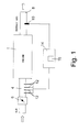
- Number 1 in Figure 1 indicates an internal combustion engine of a vehicle (not shown) comprising an air intake conduit 4 for feeding air into the combustion chambers of the cylinders of engine 1 and fitted with a butterfly valve 6 for regulating the amount of air supplied to engine 1; and an exhaust conduit 8 for discharging the exhaust gases produced by engine 1 and fitted with an oxygen concentration (lambda) sensor 10 for generating a composition signal S depending on the oxygen difference in the exhaust gases with respect to the stoichiometric condition (i.e. correlated to the air/fuel ratio of the burnt mixture) and therefore containing information relative to any variation in quality between the fuel actually used and the reference fuel used to calibrate the engine.
- an air intake conduit 4 for feeding air into the combustion chambers of the cylinders of engine 1 and fitted with a butterfly valve 6 for regulating the amount of air supplied to engine 1
- an exhaust conduit 8 for discharging the exhaust gases produced by engine 1 and fitted with an oxygen concentration (lambda) sensor 10 for generating a composition signal S depending on the oxygen difference
- a number of injectors 12 are located along, and provide for injecting fuel into, intake conduit 4.
- Fuel injection of engine 1 is controlled by a central control unit 14, which receives the composition signal S generated by oxygen concentration sensor 10 and a number of information signals correlated to engine quantities, such as engine speed and load, determined on engine 1, and which generates output signals for driving injectors 12.
- Central control unit 14 comprises a memory 16 for storing a value map - hereinafter referred to as a calibration map - containing calibration injection times TJC for each injector 12 in each operating state of engine 1 - defined by the speed and load of engine 1 - and which are defined at the initial engine 1 calibration stage using a reference fuel, and are used by central control unit 14 to generate drive signals for injectors 12.
- a value map - hereinafter referred to as a calibration map - containing calibration injection times TJC for each injector 12 in each operating state of engine 1 - defined by the speed and load of engine 1 - and which are defined at the initial engine 1 calibration stage using a reference fuel, and are used by central control unit 14 to generate drive signals for injectors 12.
- Memory 16 also stores an engine 1 reference condition, which is established at the initial engine 1 calibration stage as a condition governing recognition of any variation in fuel quality, and which is defined as follows: engine 1 speed within a predetermined range; engine 1 load within a predetermined range; butterfly valve 6 position within a predetermined range; and feedback injection control, using oxygen concentration sensor 10, activated for at least a predetermined time.
- engine 1 reference condition which is established at the initial engine 1 calibration stage as a condition governing recognition of any variation in fuel quality, and which is defined as follows: engine 1 speed within a predetermined range; engine 1 load within a predetermined range; butterfly valve 6 position within a predetermined range; and feedback injection control, using oxygen concentration sensor 10, activated for at least a predetermined time.
- Memory 16 also stores a reference injection time TJR - for the purpose explained later on - which is determined at the initial engine 1 calibration stage and in said reference condition of engine 1 using the reference fuel.
- Memory 16 also stores a first and second proportion coefficient KF1, KF2, and a first, second and third threshold value TH1, TH2, TH3, which are determined at the initial engine 1 calibration stage as a function of the speed and load of engine 1, and the purpose of which is explained later on.
- memory 16 also stores an applied correction coefficient KCA, which is updated periodically by central control unit 14 as described in detail later on, and which indicates the injection correction required to take into account the difference between the fuel actually used and the reference fuel used at the engine 1 calibration stage to calculate calibration injection times TJC.
- KCA applied correction coefficient
- central control unit 14 performs the operations described below with reference to Figure 2 to determine the quality of the fuel actually used and to update the applied correction coefficient KCA used to adapt injection to any variations in the quality of the fuel used.
- central control unit 14 determines the presence of engine 1 operating conditions permitting reliable interpretation of the information from oxygen concentration sensor 10 and, hence, implementation of the method according to the present invention.
- oxygen concentration sensor 10 is deemed reliable when engine 1 is in the steady operating state; engine 1 is thermally stable; the voltage of the vehicle battery (not shown) is correct; and there are no faults on engine 1, oxygen concentration sensor 10, injectors 12 or central control unit 14. Such conditions may be determined, for example, by reading the logic states of corresponding logic flags stored in memory 16.
- block 100 If the information from oxygen concentration sensor 10 is reliable (YES output of block 100), block 100 goes on to a block 110; conversely, if the information from oxygen concentration sensor 10 is not reliable (NO output of block 100), block 100 goes back to its own input to repeat the check until the information from oxygen concentration sensor 10 is deemed reliable.
- central control unit 14 determines whether the operating condition of engine 1 - defined by the speed and load of engine 1, by the position of butterfly valve 6, and by feedback injection control using oxygen concentration sensor 10 - matches the reference condition defined above.
- block 110 If the operating condition of engine 1 matches the reference condition (YES output of block 110), block 110 goes on to a block 120; conversely, if the operating condition is other than the reference condition (NO output of block 110), block 110 goes back to block 100 to repeat the checks until the operating condition of engine 1 matches the reference condition.
- Block 120 calculates an intermediate injection time TJM equal to the mean value of an N number of operating injection times TJO of injectors 12 in the current operating state of engine 1, and wherein N is the numeric value memorized in memory 16 at the engine 1 calibration stage.
- Block 120 then goes on to a block 130, in which central control unit 14 determines whether intermediate injection time TJM is within a predetermined range comprising reference injection time TJR, i.e. determines whether: TJR-TH1 ⁇ TJM ⁇ TJR+TH1 where TH1 is the first threshold value memorized in memory 16.
- central control unit 14 continues calculating operating injection times TJO of injectors 12 using the applied correction coefficient KCA stored in memory 16.
- central control unit 14 determines, as an absolute value, the variation V in intermediate injection time TJM with respect to reference injection time TJR according to the equation:
- Block 140 then goes on to a block 150 in which central control unit 14 determines whether variation V is below the second threshold value TH2 memorized in memory 16.
- Block 160 then goes on to a block 190 described later on.
- central control unit 14 determines whether variation V is between second threshold value TH2 and the third threshold value TH3 memorized in memory 16 and greater than second threshold value TH2.
- variation V is between the second and third threshold values TH2, TH3 (YES output of block 170), block 170 goes on to a block 180; conversely, if variation V is above third threshold value TH3 (NO output of block 170), this means the calculated intermediate injection time TJM is unreliable by differing excessively from respective reference injection time TJR, so that block 170 goes back to block 100.
- the calculated current correction coefficient KCN therefore becomes the applied correction coefficient KCA used to calculate operating injection times TJO in subsequent engine cycles.
- Block 200 then goes on to a block 210 in which central control unit 14 modifies reference injection time TJR as a function of the value of intermediate injection time TJM.
- the updated applied correction coefficient KCA is then used by central control unit 14 to calculate subsequent operating injection times TJO as described above.
- the operations described above with reference to blocks 100-210 may either be performed cyclically whenever the conditions described with reference to blocks 100 and 110 are determined, or only once, each time engine 1 is turned on.
- control method provides for fully automatically recognizing the quality of any type of gaseous or liquid fuel, and for adapting injection as a function of a variation in fuel quality.
- the control method according to the present invention also provides for minimizing any loss in performance of the engine, and for maintaining emissions within legal limits.
- block 100 - in which central control unit 14 determines the presence of engine 1 operating conditions permitting reliable interpretation of the information from oxygen concentration sensor 10 - need not determine a steady operating state of engine 1.
- central control unit 14, as opposed to N number of any operating injection times TJO, will only take into account N operating injection times TJO relative to the same operating state of engine 1, or to operating states of engine 1 differing in a way which has no effect on the calculation of intermediate injection time TJM.
- intermediate injection time TJM and reference injection time TJR may be determined in different engine operating conditions. In which case, however, the comparison made in block 130 would differ from that described, and would have to take into account the relationship between the operating condition in which intermediate injection time TJM is determined, and that in which reference injection time TJR is determined.
- intermediate injection time TJM may be calculated as a function of the N operating injection times TJO in a way other than that described.
Landscapes
- Engineering & Computer Science (AREA)
- Chemical & Material Sciences (AREA)
- Combustion & Propulsion (AREA)
- Mechanical Engineering (AREA)
- General Engineering & Computer Science (AREA)
- Oil, Petroleum & Natural Gas (AREA)
- Electrical Control Of Air Or Fuel Supplied To Internal-Combustion Engine (AREA)
- Combined Controls Of Internal Combustion Engines (AREA)
Applications Claiming Priority (2)
| Application Number | Priority Date | Filing Date | Title |
|---|---|---|---|
| ITTO980913 | 1998-10-28 | ||
| IT1998TO000913A IT1305143B1 (it) | 1998-10-28 | 1998-10-28 | Metodo di controllo dell'iniezione in un motore a combustione internain funzione della qualita' del combustibile utilizzato. |
Publications (3)
| Publication Number | Publication Date |
|---|---|
| EP0997627A2 true EP0997627A2 (de) | 2000-05-03 |
| EP0997627A3 EP0997627A3 (de) | 2000-11-08 |
| EP0997627B1 EP0997627B1 (de) | 2004-08-11 |
Family
ID=11417142
Family Applications (1)
| Application Number | Title | Priority Date | Filing Date |
|---|---|---|---|
| EP99121412A Expired - Lifetime EP0997627B1 (de) | 1998-10-28 | 1999-10-27 | Steuerungsverfahren für die Steuerung der Einspritzung eines Verbrennungsmotors als Funktion der Krafstoffqualität |
Country Status (6)
| Country | Link |
|---|---|
| US (1) | US6279559B1 (de) |
| EP (1) | EP0997627B1 (de) |
| AU (1) | AU754933B2 (de) |
| DE (1) | DE69919294T2 (de) |
| ES (1) | ES2227952T3 (de) |
| IT (1) | IT1305143B1 (de) |
Cited By (3)
| Publication number | Priority date | Publication date | Assignee | Title |
|---|---|---|---|---|
| DE102006043702B3 (de) * | 2006-09-18 | 2007-07-26 | Audi Ag | Verfahren und Vorrichtung zum Betreiben einer Brennkraftmaschine |
| EP1775584A3 (de) * | 2005-10-11 | 2011-09-14 | Continental Automotive GmbH | Verfahren und Vorrichtung zur Erkennung der Qualität eines Kraftstoffs für Brennkraftmaschine |
| IT202100030989A1 (it) | 2021-12-09 | 2023-06-09 | Fpt Ind Spa | Sistema di alimentazione di un motore ad accensione comandata |
Families Citing this family (3)
| Publication number | Priority date | Publication date | Assignee | Title |
|---|---|---|---|---|
| EP2013464B1 (de) * | 2006-04-18 | 2009-12-23 | Iav Gmbh Ingenieurgesellschaft Auto Und Verkehr | Verfahren zum einstellen des luft-/kraftstoffverhältnisses eines verbrennungsmotors |
| JP2008274883A (ja) * | 2007-05-01 | 2008-11-13 | Toyota Motor Corp | 内燃機関の制御装置 |
| JP6490137B2 (ja) * | 2017-04-19 | 2019-03-27 | 三菱電機株式会社 | インジェクタの制御装置 |
Family Cites Families (9)
| Publication number | Priority date | Publication date | Assignee | Title |
|---|---|---|---|---|
| GB2194359B (en) * | 1986-08-02 | 1990-08-22 | Fuji Heavy Ind Ltd | Air-fuel ratio control system for an automotive engine |
| WO1990006427A1 (en) * | 1988-12-10 | 1990-06-14 | Robert Bosch Gmbh | Fuel control system |
| JP2826601B2 (ja) * | 1990-01-19 | 1998-11-18 | 三菱自動車工業株式会社 | 燃料ブレンド率検出方法 |
| JPH03233151A (ja) * | 1990-02-08 | 1991-10-17 | Suzuki Motor Corp | 内燃機関の燃料供給制御装置 |
| JP3259967B2 (ja) * | 1990-06-01 | 2002-02-25 | ローベルト ボツシユ ゲゼルシヤフト ミツト ベシユレンクテル ハフツング | 燃料と空気の混合気を適応調節する方法 |
| US5158062A (en) * | 1990-12-10 | 1992-10-27 | Ford Motor Company | Adaptive air/fuel ratio control method |
| JPH04224244A (ja) * | 1990-12-21 | 1992-08-13 | Honda Motor Co Ltd | エンジンの空燃比制御装置 |
| US5467755A (en) * | 1994-08-25 | 1995-11-21 | Ford Motor Company | Method and system for controlling flexible fuel vehicle fueling |
| US5775298A (en) * | 1996-12-09 | 1998-07-07 | General Motors Corporation | Internal combustion engine control |
-
1998
- 1998-10-28 IT IT1998TO000913A patent/IT1305143B1/it active
-
1999
- 1999-10-27 ES ES99121412T patent/ES2227952T3/es not_active Expired - Lifetime
- 1999-10-27 DE DE69919294T patent/DE69919294T2/de not_active Expired - Fee Related
- 1999-10-27 EP EP99121412A patent/EP0997627B1/de not_active Expired - Lifetime
- 1999-10-28 AU AU57090/99A patent/AU754933B2/en not_active Ceased
- 1999-10-28 US US09/428,519 patent/US6279559B1/en not_active Expired - Fee Related
Cited By (4)
| Publication number | Priority date | Publication date | Assignee | Title |
|---|---|---|---|---|
| EP1775584A3 (de) * | 2005-10-11 | 2011-09-14 | Continental Automotive GmbH | Verfahren und Vorrichtung zur Erkennung der Qualität eines Kraftstoffs für Brennkraftmaschine |
| DE102006043702B3 (de) * | 2006-09-18 | 2007-07-26 | Audi Ag | Verfahren und Vorrichtung zum Betreiben einer Brennkraftmaschine |
| IT202100030989A1 (it) | 2021-12-09 | 2023-06-09 | Fpt Ind Spa | Sistema di alimentazione di un motore ad accensione comandata |
| US12607150B2 (en) | 2021-12-09 | 2026-04-21 | Fpt Industrial S.P.A. | Fuel system for a spark ignition engine |
Also Published As
| Publication number | Publication date |
|---|---|
| EP0997627B1 (de) | 2004-08-11 |
| ES2227952T3 (es) | 2005-04-01 |
| DE69919294T2 (de) | 2005-09-08 |
| US6279559B1 (en) | 2001-08-28 |
| IT1305143B1 (it) | 2001-04-10 |
| AU5709099A (en) | 2000-05-04 |
| AU754933B2 (en) | 2002-11-28 |
| EP0997627A3 (de) | 2000-11-08 |
| ITTO980913A1 (it) | 2000-04-28 |
| DE69919294D1 (de) | 2004-09-16 |
Similar Documents
| Publication | Publication Date | Title |
|---|---|---|
| JP4292909B2 (ja) | 内燃機関の空燃比制御装置 | |
| US5426935A (en) | Air-fuel ratio control system for internal combustion engines | |
| JP2008309036A (ja) | 燃料推定装置 | |
| US4441473A (en) | Closed loop mixture control using learning data resettable for fuel evaporation compensation | |
| US5836292A (en) | Heater controller for an air-fuel ratio sensor | |
| EP0997627B1 (de) | Steuerungsverfahren für die Steuerung der Einspritzung eines Verbrennungsmotors als Funktion der Krafstoffqualität | |
| EP0997628B1 (de) | Steuerungsverfahren für die Steuerung der Einspritzung eines Verbrennungsmotor als Funktion der Krafstoffqualität | |
| JP5373687B2 (ja) | バイフューエルエンジンのアイドル回転速度制御装置 | |
| US5706654A (en) | Air-fuel ratio control device for an internal combustion engine | |
| KR970007211B1 (ko) | 내연기관 제어장치 | |
| JP4483823B2 (ja) | 燃料噴射制御装置 | |
| US10690083B2 (en) | Air-fuel ration control apparatus for engine | |
| JP2016109030A (ja) | バイフューエルエンジンの空燃比制御装置 | |
| US5617836A (en) | Engine control system for producing and responding to an index of maturity of adaptive learing | |
| CN100390392C (zh) | 发动机空燃比控制系统 | |
| JP2004092529A (ja) | 内燃機関の制御装置 | |
| US6023965A (en) | Method of compensating for boil-off alcohol in a flexible fueled vehicle with a PCV solenoid | |
| JP3882441B2 (ja) | 内燃機関の空燃比制御装置 | |
| JP2817106B2 (ja) | 内燃エンジンの空燃比制御方法 | |
| JP2008223578A (ja) | 内燃機関の空燃比制御装置 | |
| JPH0694848B2 (ja) | Lpgエンジンの空燃比学習制御方法 | |
| JPH062590A (ja) | 内燃機関の空燃比制御方法 | |
| JP2005105978A (ja) | 内燃機関の制御装置 | |
| JP2010025062A (ja) | 内燃機関の燃料噴射制御装置 | |
| JPH0544525A (ja) | Lpgエンジンの空燃比制御装置 |
Legal Events
| Date | Code | Title | Description |
|---|---|---|---|
| PUAI | Public reference made under article 153(3) epc to a published international application that has entered the european phase |
Free format text: ORIGINAL CODE: 0009012 |
|
| AK | Designated contracting states |
Kind code of ref document: A2 Designated state(s): DE ES FR GB NL SE |
|
| AX | Request for extension of the european patent |
Free format text: AL;LT;LV;MK;RO;SI |
|
| RIN1 | Information on inventor provided before grant (corrected) |
Inventor name: ZANET, CLAUDIO Inventor name: VOLPIN, ALESSANDRO Inventor name: FORNATTO, ENRICO Inventor name: CIUTI, STEFANO Inventor name: MAURO, MARCO |
|
| PUAL | Search report despatched |
Free format text: ORIGINAL CODE: 0009013 |
|
| AK | Designated contracting states |
Kind code of ref document: A3 Designated state(s): AT BE CH CY DE DK ES FI FR GB GR IE IT LI LU MC NL PT SE |
|
| AX | Request for extension of the european patent |
Free format text: AL;LT;LV;MK;RO;SI |
|
| 17P | Request for examination filed |
Effective date: 20010414 |
|
| AKX | Designation fees paid |
Free format text: DE ES FR GB NL SE |
|
| 17Q | First examination report despatched |
Effective date: 20030808 |
|
| GRAP | Despatch of communication of intention to grant a patent |
Free format text: ORIGINAL CODE: EPIDOSNIGR1 |
|
| GRAS | Grant fee paid |
Free format text: ORIGINAL CODE: EPIDOSNIGR3 |
|
| GRAA | (expected) grant |
Free format text: ORIGINAL CODE: 0009210 |
|
| AK | Designated contracting states |
Kind code of ref document: B1 Designated state(s): DE ES FR GB NL SE |
|
| REG | Reference to a national code |
Ref country code: GB Ref legal event code: FG4D |
|
| REF | Corresponds to: |
Ref document number: 69919294 Country of ref document: DE Date of ref document: 20040916 Kind code of ref document: P |
|
| REG | Reference to a national code |
Ref country code: SE Ref legal event code: TRGR |
|
| REG | Reference to a national code |
Ref country code: ES Ref legal event code: FG2A Ref document number: 2227952 Country of ref document: ES Kind code of ref document: T3 |
|
| ET | Fr: translation filed | ||
| PLBE | No opposition filed within time limit |
Free format text: ORIGINAL CODE: 0009261 |
|
| STAA | Information on the status of an ep patent application or granted ep patent |
Free format text: STATUS: NO OPPOSITION FILED WITHIN TIME LIMIT |
|
| 26N | No opposition filed |
Effective date: 20050512 |
|
| PGFP | Annual fee paid to national office [announced via postgrant information from national office to epo] |
Ref country code: ES Payment date: 20080829 Year of fee payment: 10 |
|
| PGFP | Annual fee paid to national office [announced via postgrant information from national office to epo] |
Ref country code: NL Payment date: 20080829 Year of fee payment: 10 |
|
| PGFP | Annual fee paid to national office [announced via postgrant information from national office to epo] |
Ref country code: DE Payment date: 20081031 Year of fee payment: 10 |
|
| PGFP | Annual fee paid to national office [announced via postgrant information from national office to epo] |
Ref country code: SE Payment date: 20081014 Year of fee payment: 10 |
|
| PGFP | Annual fee paid to national office [announced via postgrant information from national office to epo] |
Ref country code: FR Payment date: 20081008 Year of fee payment: 10 |
|
| PGFP | Annual fee paid to national office [announced via postgrant information from national office to epo] |
Ref country code: GB Payment date: 20081027 Year of fee payment: 10 |
|
| REG | Reference to a national code |
Ref country code: NL Ref legal event code: V1 Effective date: 20100501 |
|
| EUG | Se: european patent has lapsed | ||
| REG | Reference to a national code |
Ref country code: FR Ref legal event code: ST Effective date: 20100630 |
|
| PG25 | Lapsed in a contracting state [announced via postgrant information from national office to epo] |
Ref country code: NL Free format text: LAPSE BECAUSE OF NON-PAYMENT OF DUE FEES Effective date: 20100501 Ref country code: FR Free format text: LAPSE BECAUSE OF NON-PAYMENT OF DUE FEES Effective date: 20091102 Ref country code: DE Free format text: LAPSE BECAUSE OF NON-PAYMENT OF DUE FEES Effective date: 20100501 |
|
| PG25 | Lapsed in a contracting state [announced via postgrant information from national office to epo] |
Ref country code: GB Free format text: LAPSE BECAUSE OF NON-PAYMENT OF DUE FEES Effective date: 20091027 |
|
| REG | Reference to a national code |
Ref country code: ES Ref legal event code: FD2A Effective date: 20110310 |
|
| PG25 | Lapsed in a contracting state [announced via postgrant information from national office to epo] |
Ref country code: SE Free format text: LAPSE BECAUSE OF NON-PAYMENT OF DUE FEES Effective date: 20091028 |
|
| PG25 | Lapsed in a contracting state [announced via postgrant information from national office to epo] |
Ref country code: ES Free format text: LAPSE BECAUSE OF NON-PAYMENT OF DUE FEES Effective date: 20110309 |
|
| PG25 | Lapsed in a contracting state [announced via postgrant information from national office to epo] |
Ref country code: ES Free format text: LAPSE BECAUSE OF NON-PAYMENT OF DUE FEES Effective date: 20091028 |