EP0999416A2 - Procédé pour installer des paneaux de chauffage pour chauffage par le sol - Google Patents
Procédé pour installer des paneaux de chauffage pour chauffage par le sol Download PDFInfo
- Publication number
- EP0999416A2 EP0999416A2 EP99308772A EP99308772A EP0999416A2 EP 0999416 A2 EP0999416 A2 EP 0999416A2 EP 99308772 A EP99308772 A EP 99308772A EP 99308772 A EP99308772 A EP 99308772A EP 0999416 A2 EP0999416 A2 EP 0999416A2
- Authority
- EP
- European Patent Office
- Prior art keywords
- panels
- pipe
- heating
- channels
- floor
- Prior art date
- Legal status (The legal status is an assumption and is not a legal conclusion. Google has not performed a legal analysis and makes no representation as to the accuracy of the status listed.)
- Withdrawn
Links
Images


Classifications
-
- F—MECHANICAL ENGINEERING; LIGHTING; HEATING; WEAPONS; BLASTING
- F24—HEATING; RANGES; VENTILATING
- F24D—DOMESTIC- OR SPACE-HEATING SYSTEMS, e.g. CENTRAL HEATING SYSTEMS; DOMESTIC HOT-WATER SUPPLY SYSTEMS; ELEMENTS OR COMPONENTS THEREFOR
- F24D3/00—Hot-water central heating systems
- F24D3/12—Tube and panel arrangements for ceiling, wall, or underfloor heating
- F24D3/14—Tube and panel arrangements for ceiling, wall, or underfloor heating incorporated in a ceiling, wall or floor
- F24D3/141—Tube mountings specially adapted therefor
-
- Y—GENERAL TAGGING OF NEW TECHNOLOGICAL DEVELOPMENTS; GENERAL TAGGING OF CROSS-SECTIONAL TECHNOLOGIES SPANNING OVER SEVERAL SECTIONS OF THE IPC; TECHNICAL SUBJECTS COVERED BY FORMER USPC CROSS-REFERENCE ART COLLECTIONS [XRACs] AND DIGESTS
- Y02—TECHNOLOGIES OR APPLICATIONS FOR MITIGATION OR ADAPTATION AGAINST CLIMATE CHANGE
- Y02B—CLIMATE CHANGE MITIGATION TECHNOLOGIES RELATED TO BUILDINGS, e.g. HOUSING, HOUSE APPLIANCES OR RELATED END-USER APPLICATIONS
- Y02B30/00—Energy efficient heating, ventilation or air conditioning [HVAC]
Definitions
- This invention relates to a method of installing underfloor heating in a building.
- the method of the present invention has been developed to make it easier to install underfloor heating in floors which are constructed either as a timber floor deck which is fully supported on rigid insulation (normally referred to as a fully-floating floor) or as a screeded floor over insulation.
- the invention addresses two requirements:
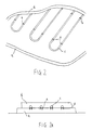
- FIGs 1 and 1a show how rigid insulation panels (a) are covered with steel reinforcing mesh (b) and how the heating pipe (c) is tied to the top of the mesh. Screed (d) is then laid over the whole.
- Figures 2 and 2a show how rigid insulation panels (a) have heating pipe (c) fixed in place using staples (e) which catch into a fabric surface which is bonded to the top surface of the insulation. Screed (d) is then laid over the whole.
- FIGS 3 and 3a show how rigid insulation panels (a) have fixing rails (f) attached and how the heating pipe (c) is held in place by them. Screed (d) is then laid over the whole.
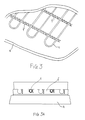
- Figures 4, 4a and 4b show rigid insulation (a) with heat diffuser plates (g) and heating pipe (c) beneath a timber floor deck (h).
- the diffuser plates (g) are typically formed from hard-temper aluminium sheets 0.4 to 0.7 mm. thick and they have channels to accept the heating pipe. The width of the channels formed in the plates corresponds with the outside diameter of the heating pipe.
- Figures 4, 4a and 4b show a configuration having two channels per plate, but it is also common to have a single channel per plate when a plate is to be used with larger diameter pipe.
- the diffuser plates (g) are set on top of the grooved insulation in such a way that each preformed diffuser plate (g) engages with the channels formed in the top of the insulation (a).
- the heating pipe (c) is pressed into the channels in the diffuser plate (g) which then acts as a fin to the pipe (c), conducting the heat away from the pipe (c) and spreading it evenly across the underside of the floor deck.
- the floor deck (h) is typically chipboard, plywood, cement-bonded particle board or timber planks.
- the method of the present invention has been developed to address these shortcomings.
- a method of installing underfloor heating in a building including producing a floor plan, designing a pipe layout including supply and return lines from and to a heat source, which pipe layout is based on the use of modular insulating panels formed with communicating channels in which heating pipes can be fitted, producing and supplying the modular insulating panels to site together with instructions concerning the layout which is required, placing the modular insulating panels in position in accordance with the instructions, inserting the pipes in the channels, and placing flooring over the pipes.
- the floor plan is preferably a CAD design and the pipe layout is preferably added to the floor plan using a computer.
- the pipe layout is preferably overlaid with the layout of the insulation panels which are to be set on the floor and the pipe layout then transferred to each individual panel and transformed into computer programs sent to a computer-controlled machining centre in which production of the panels is effected.
- the invention thus involves harnessing the power of the computer to simplify the production and installation process.
- the individual panels are preferably foamed or expanded polystyrene panels having a thickness of 40 or 50 mm. and a standard module size of 2,400 mm. by 1,200 mm.
- the polystyrene panels may be constructed as described in co-pending Application No. of even date herewith.
- the panels may be covered with aluminium foil which extends over the top surface of each panel and is a close fit in the channels formed in the panels so that, when the heating pipe is inserted in the channels, the aluminium foil acts as a heat diffuser.
- the method of the present invention can include the use of a panel 10 of rigid insulation, for example, foamed polystyrene, which has a channel 11 formed in its top surface into which heating pipe 12 can be pressed.
- a panel 10 of rigid insulation for example, foamed polystyrene
- the pattern of the pipe channel in each panel 10 is determined by the panel's position within a larger pipe layout design, such as that shown in Figure 5, which has been designed to suit the heating requirements of each complete room or space and which is larger than a single panel in area.
- a CAD drawing is produced showing the floor plans of the area to be heated.
- This CAD drawing may be the architect's original drawing and can be moved electronically, by e-mail, between all the professionals involved in the project.
- An underfloor heating designer adds a layer to the original CAD drawing to show the precise position of the heating pipework, taking into account the position of any obstructions in the floor area.
- the designer uses the CAD system to overlay the pipework design with the layout of the insulation panels which are to be set on the floor base.
- a drawing such as that shown in Figure 5 is thus produced.
- the pipe layout design is transferred by means of a computer onto a number of individual panels, as shown in Figure 6, in such a way that the individual panels form a jigsaw of panels which, when placed on a floor in the correct association one with another, collectively create the pipe channels of the larger pipe layout design illustrated in Figure 5.
- the computer takes the information which it receives, based on the information corresponding to the drawing of Figure 5, and turns this into unique programmes which can be used in a computer-controlled machining centre in which each insulation panel is machined individually using a routing cutter to create a jigsaw of insulation panels which are simply set alongside each other on site.
- Each panel can be numbered individually, and it is even possible to arrange for the panels to be stacked in the correct sequence on the pallet on which they are to be delivered to the site.
- a significant feature of the invention is thus to use the computer to transfer the pipe layout design on to the individual insulation panels.
- Another important step in the development of the method of the present invention is the realisation that it is possible to create unique panels which are individual jigsaw pieces of a much larger layout design.
- the insulation panels are set on the ground in the required pattern, in accordance with instructions, e.g. a panel layout, supplied to the on-site installer either with the panels or separately.
- Heating pipe is then pressed into each circuit , the flow and return pipes of each circuit are then connected to the manifold assembly and each circuit is pressure-tested.
- a designer of a heating/cooling system is able to design a system for an entire space and then transfer that design onto a pattern of individual panels of invention which, when assembled on site in the correct association one with another are able to represent the design layout for the entire space.
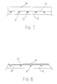
- Figure 7 shows a floor section with a foamed polystyrene panel being used in a screeded floor.
- the foamed or expanded polystyrene panel 10 has channels 11 formed in its top surface which is (optionally) covered with aluminium foil 13 which is pressed down into the channels and which acts as a heat diffuser to conduct heat away from the pipe 12 and spread it beneath the screed 14. Heating pipe 12 is pressed into the channels before the screed 14 is laid.
- Figure 8 shows a floor section with a foamed polystyrene panel 10, as described above, being used in a fully floating timber floor. Aluminium foil is again pressed down into the channels in the panel 10 and acts as a heat diffuser to conduct heat away from the pipe 12 and spread it beneath the timber floor deck 15. The heating pipe 12 is pressed into the channels before the floor deck 15 is laid.
- the method of the present invention offers the following advantages over current practice:
- the method of the present invention makes installation of underfloor heating a simple and inexpensive operation. Rigid insulation would have to be installed in a screeded floor or a floating timber floor construction in any event, even if a different non-underfloor heating system was to be used. There is very little additional cost associated with fitting the heating pipe and this does need specialist labour.
- a panel having aluminium foil across its top surface it is possible to use a panel which has, along the length of the pipe channel, wider channel sections formed between short narrow sections
- the short narrow sections of channel are of such width that they receive the heating pipe as a press fit and the wider sections are intended be filled with an inexpensive thermally-conductive material such as a sand/cement mix which acts as a cheaper alternative to an aluminium foil heat diffuser.
- an inexpensive thermally-conductive material such as a sand/cement mix which acts as a cheaper alternative to an aluminium foil heat diffuser.
- panel which can be used, in addition to the panels described above, is a panel with pipe channels but no aluminium foil. This can be used where the pipe is to remain insulated, for example, where the pipe crosses floor areas where minimal heating is required.
Landscapes
- Engineering & Computer Science (AREA)
- Physics & Mathematics (AREA)
- Thermal Sciences (AREA)
- Chemical & Material Sciences (AREA)
- Combustion & Propulsion (AREA)
- Mechanical Engineering (AREA)
- General Engineering & Computer Science (AREA)
- Steam Or Hot-Water Central Heating Systems (AREA)
- Floor Finish (AREA)
Applications Claiming Priority (2)
| Application Number | Priority Date | Filing Date | Title |
|---|---|---|---|
| GBGB9824084.9A GB9824084D0 (en) | 1998-11-05 | 1998-11-05 | Underfloor heating panels |
| GB9824084 | 1998-11-05 |
Publications (2)
| Publication Number | Publication Date |
|---|---|
| EP0999416A2 true EP0999416A2 (fr) | 2000-05-10 |
| EP0999416A3 EP0999416A3 (fr) | 2002-08-21 |
Family
ID=10841784
Family Applications (1)
| Application Number | Title | Priority Date | Filing Date |
|---|---|---|---|
| EP99308772A Withdrawn EP0999416A3 (fr) | 1998-11-05 | 1999-11-04 | Procédé pour installer des paneaux de chauffage pour chauffage par le sol |
Country Status (2)
| Country | Link |
|---|---|
| EP (1) | EP0999416A3 (fr) |
| GB (2) | GB9824084D0 (fr) |
Cited By (5)
| Publication number | Priority date | Publication date | Assignee | Title |
|---|---|---|---|---|
| EP1813874A3 (fr) * | 2006-01-30 | 2009-03-25 | Polypipe Building Products Ltd. | Appareil et procédé de chauffage d'un espace |
| GB2490475A (en) * | 2011-02-24 | 2012-11-07 | John David Purnell | Underfloor heating panel |
| WO2014204318A1 (fr) * | 2013-06-18 | 2014-12-24 | Hunton Fiber As | Appareil pour produire un élément à spires de plaque de fibres sous plancher pour chauffage sous plancher |
| CN105908938A (zh) * | 2016-05-11 | 2016-08-31 | 张勇 | 一种节能高效地暖装饰陶瓷 |
| DE102024001115A1 (de) * | 2024-04-08 | 2025-10-09 | Thomas Schenk | Verfahren und Vorrichtung zur Herstellung eines Grundkörpers für eine flächige Temperiereinheit |
Families Citing this family (1)
| Publication number | Priority date | Publication date | Assignee | Title |
|---|---|---|---|---|
| GB2640538A (en) * | 2024-04-23 | 2025-10-29 | Uh Ai Ltd | Boards for an underfloor heating system |
Family Cites Families (7)
| Publication number | Priority date | Publication date | Assignee | Title |
|---|---|---|---|---|
| DE2805070C2 (de) * | 1978-02-07 | 1982-04-29 | Dier, geb.Neurohr, Irmgard, 6680 Neunkirchen | Grundplatte für eine Heiz- und/oder Kühleinheit |
| EP0039446A1 (fr) * | 1980-04-24 | 1981-11-11 | Jiri Elias | Dispositif de construction pour le chauffage surfacique de locaux |
| DE3300607A1 (de) * | 1983-01-11 | 1984-07-12 | Hans Dr.-Ing. 7410 Reutlingen Lutz | Fluessigkeitsflaechenheizung fuer fussboeden |
| DE3401868C2 (de) * | 1983-07-18 | 1986-11-27 | Hartmut 5378 Blankenheim Franzen | Platte zum Verlegen von Heizungsrohren von Fußbodenheizungen |
| SE8902324L (sv) * | 1989-06-27 | 1990-12-28 | Bengt Valdemar Eggemar | Foerfarande och anordning vid vaermevaexling |
| EP0696775A1 (fr) * | 1993-04-21 | 1996-02-14 | Hitachi, Ltd. | Système de conception et de production assisté par ordinateur pour la disposition d'éléments et l'interconnexion de tuyaux |
| GB2321302A (en) * | 1997-01-20 | 1998-07-22 | John Lipscomb | Modular heat exchanger |
-
1998
- 1998-11-05 GB GBGB9824084.9A patent/GB9824084D0/en not_active Ceased
-
1999
- 1999-11-04 GB GB9926035A patent/GB2343507B/en not_active Expired - Fee Related
- 1999-11-04 EP EP99308772A patent/EP0999416A3/fr not_active Withdrawn
Cited By (6)
| Publication number | Priority date | Publication date | Assignee | Title |
|---|---|---|---|---|
| EP1813874A3 (fr) * | 2006-01-30 | 2009-03-25 | Polypipe Building Products Ltd. | Appareil et procédé de chauffage d'un espace |
| GB2490475A (en) * | 2011-02-24 | 2012-11-07 | John David Purnell | Underfloor heating panel |
| WO2014204318A1 (fr) * | 2013-06-18 | 2014-12-24 | Hunton Fiber As | Appareil pour produire un élément à spires de plaque de fibres sous plancher pour chauffage sous plancher |
| CN105908938A (zh) * | 2016-05-11 | 2016-08-31 | 张勇 | 一种节能高效地暖装饰陶瓷 |
| CN105908938B (zh) * | 2016-05-11 | 2019-02-26 | 深圳市中装建设集团股份有限公司 | 一种节能高效地暖装饰陶瓷 |
| DE102024001115A1 (de) * | 2024-04-08 | 2025-10-09 | Thomas Schenk | Verfahren und Vorrichtung zur Herstellung eines Grundkörpers für eine flächige Temperiereinheit |
Also Published As
| Publication number | Publication date |
|---|---|
| GB9824084D0 (en) | 1998-12-30 |
| GB9926035D0 (en) | 2000-01-12 |
| EP0999416A3 (fr) | 2002-08-21 |
| GB2343507B (en) | 2002-12-11 |
| GB2343507A (en) | 2000-05-10 |
Similar Documents
| Publication | Publication Date | Title |
|---|---|---|
| FI106406B (fi) | Moduuli käytettäväksi lattialämmitys-/jäähdytysjärjestelmässä, menetelmä lattialämmitys-/jäähdytysjärjestelmän asentamiseksi ja lattialämmitys-/jäähdytysjärjestelmä | |
| US5788152A (en) | Floor heating system | |
| CA2419486C (fr) | Platine de montage de tube pour systeme de chauffage par rayonnement | |
| US6092587A (en) | Heating/cooling systems | |
| US8028742B2 (en) | Radiant heating/cooling tubing substrate with in plane bus | |
| US20060107618A1 (en) | Modular radiant heat panel system | |
| CA2185548C (fr) | Systeme de chauffage au sol | |
| US6009612A (en) | Apparatus for attaching radiating plate to holders of modular unit for radiant floor and wall hydronic heating systems | |
| EP1055087B1 (fr) | Dispositif de chauffage de sol a cable auto-regulateur | |
| EP0999416A2 (fr) | Procédé pour installer des paneaux de chauffage pour chauffage par le sol | |
| EP4259976B1 (fr) | Panneau de mur chauffant et élément de coin de masquage de bord de panneau de mur chauffant | |
| EP0999415A2 (fr) | Panneaux de chauffage pour chauffage par le sol | |
| GB2321302A (en) | Modular heat exchanger | |
| CA2070456C (fr) | Plancher chauffant | |
| RU239085U1 (ru) | Модуль тёплого водяного чернового пола сухого монтажа | |
| JP2000220855A (ja) | 乾式遮音二重床のベースパネルを利用した床暖房システムとその施工方法 | |
| AU701134B2 (en) | Floor heating system | |
| JPH01291021A (ja) | 木質系温水式床暖房パネルおよびその施工方法 | |
| EP1591603A1 (fr) | Procédé de construction d'un sol chauffé électriquement | |
| JPH11190526A (ja) | 床暖房用パネル | |
| JP2000297943A (ja) | 床暖房用温水マットの敷設方法 | |
| JPH0399126A (ja) | 潜熱蓄熱板およびそれを用いた潜熱蓄熱式電気床暖房装置 | |
| JPH0614814U (ja) | 床暖房装置 | |
| JPH0624127U (ja) | 床パネル | |
| JPH04261947A (ja) | 床暖房用alc版 |
Legal Events
| Date | Code | Title | Description |
|---|---|---|---|
| PUAI | Public reference made under article 153(3) epc to a published international application that has entered the european phase |
Free format text: ORIGINAL CODE: 0009012 |
|
| AK | Designated contracting states |
Kind code of ref document: A2 Designated state(s): AT BE CH CY DE DK ES FI FR GB GR IE IT LI LU MC NL PT SE |
|
| AX | Request for extension of the european patent |
Free format text: AL;LT;LV;MK;RO;SI |
|
| PUAL | Search report despatched |
Free format text: ORIGINAL CODE: 0009013 |
|
| AK | Designated contracting states |
Kind code of ref document: A3 Designated state(s): AT BE CH CY DE DK ES FI FR GB GR IE IT LI LU MC NL PT SE |
|
| AX | Request for extension of the european patent |
Free format text: AL;LT;LV;MK;RO;SI |
|
| STAA | Information on the status of an ep patent application or granted ep patent |
Free format text: STATUS: THE APPLICATION IS DEEMED TO BE WITHDRAWN |
|
| 18D | Application deemed to be withdrawn |
Effective date: 20020601 |