EP1003614B1 - Prüfkopf für die ultraschallprüfung nach dem impuls-echo-verfahren - Google Patents
Prüfkopf für die ultraschallprüfung nach dem impuls-echo-verfahren Download PDFInfo
- Publication number
- EP1003614B1 EP1003614B1 EP98933515A EP98933515A EP1003614B1 EP 1003614 B1 EP1003614 B1 EP 1003614B1 EP 98933515 A EP98933515 A EP 98933515A EP 98933515 A EP98933515 A EP 98933515A EP 1003614 B1 EP1003614 B1 EP 1003614B1
- Authority
- EP
- European Patent Office
- Prior art keywords
- transducer
- transmitter
- receiver
- probe according
- electronics
- Prior art date
- Legal status (The legal status is an assumption and is not a legal conclusion. Google has not performed a legal analysis and makes no representation as to the accuracy of the status listed.)
- Expired - Lifetime
Links
- 238000002604 ultrasonography Methods 0.000 title claims abstract description 8
- 238000000034 method Methods 0.000 title claims abstract description 6
- 239000000463 material Substances 0.000 claims abstract description 11
- 239000000523 sample Substances 0.000 claims description 23
- 238000012360 testing method Methods 0.000 claims description 17
- 239000011888 foil Substances 0.000 claims description 5
- 239000003292 glue Substances 0.000 claims 3
- 239000002243 precursor Substances 0.000 claims 2
- 238000013016 damping Methods 0.000 description 8
- 239000010410 layer Substances 0.000 description 7
- 239000002033 PVDF binder Substances 0.000 description 6
- 230000005540 biological transmission Effects 0.000 description 6
- 229920002981 polyvinylidene fluoride Polymers 0.000 description 6
- 239000012790 adhesive layer Substances 0.000 description 4
- 238000007740 vapor deposition Methods 0.000 description 3
- 239000004793 Polystyrene Substances 0.000 description 2
- 238000010586 diagram Methods 0.000 description 2
- 230000000694 effects Effects 0.000 description 2
- 238000005516 engineering process Methods 0.000 description 2
- 229920002223 polystyrene Polymers 0.000 description 2
- 230000001052 transient effect Effects 0.000 description 2
- 238000013459 approach Methods 0.000 description 1
- 230000015572 biosynthetic process Effects 0.000 description 1
- 239000004020 conductor Substances 0.000 description 1
- 238000001514 detection method Methods 0.000 description 1
- 238000007599 discharging Methods 0.000 description 1
- 230000002349 favourable effect Effects 0.000 description 1
- PCHJSUWPFVWCPO-UHFFFAOYSA-N gold Chemical compound [Au] PCHJSUWPFVWCPO-UHFFFAOYSA-N 0.000 description 1
- 238000011835 investigation Methods 0.000 description 1
- 230000003071 parasitic effect Effects 0.000 description 1
- 239000002985 plastic film Substances 0.000 description 1
- 229920006255 plastic film Polymers 0.000 description 1
- 229920003229 poly(methyl methacrylate) Polymers 0.000 description 1
- 239000004926 polymethyl methacrylate Substances 0.000 description 1
- 230000002787 reinforcement Effects 0.000 description 1
- 239000011347 resin Substances 0.000 description 1
- 229920005989 resin Polymers 0.000 description 1
- 230000035945 sensitivity Effects 0.000 description 1
- 238000000926 separation method Methods 0.000 description 1
- 230000008054 signal transmission Effects 0.000 description 1
- 238000005476 soldering Methods 0.000 description 1
- 239000011343 solid material Substances 0.000 description 1
- 238000004154 testing of material Methods 0.000 description 1
- 238000012549 training Methods 0.000 description 1
- 210000003462 vein Anatomy 0.000 description 1
- XLYOFNOQVPJJNP-UHFFFAOYSA-N water Substances O XLYOFNOQVPJJNP-UHFFFAOYSA-N 0.000 description 1
Images

Classifications
-
- G—PHYSICS
- G01—MEASURING; TESTING
- G01N—INVESTIGATING OR ANALYSING MATERIALS BY DETERMINING THEIR CHEMICAL OR PHYSICAL PROPERTIES
- G01N29/00—Investigating or analysing materials by the use of ultrasonic, sonic or infrasonic waves; Visualisation of the interior of objects by transmitting ultrasonic or sonic waves through the object
- G01N29/22—Details, e.g. general constructional or apparatus details
- G01N29/24—Probes
- G01N29/2487—Directing probes, e.g. angle probes
-
- B—PERFORMING OPERATIONS; TRANSPORTING
- B06—GENERATING OR TRANSMITTING MECHANICAL VIBRATIONS IN GENERAL
- B06B—METHODS OR APPARATUS FOR GENERATING OR TRANSMITTING MECHANICAL VIBRATIONS OF INFRASONIC, SONIC, OR ULTRASONIC FREQUENCY, e.g. FOR PERFORMING MECHANICAL WORK IN GENERAL
- B06B1/00—Methods or apparatus for generating mechanical vibrations of infrasonic, sonic, or ultrasonic frequency
- B06B1/02—Methods or apparatus for generating mechanical vibrations of infrasonic, sonic, or ultrasonic frequency making use of electrical energy
- B06B1/06—Methods or apparatus for generating mechanical vibrations of infrasonic, sonic, or ultrasonic frequency making use of electrical energy operating with piezoelectric effect or with electrostriction
-
- B—PERFORMING OPERATIONS; TRANSPORTING
- B06—GENERATING OR TRANSMITTING MECHANICAL VIBRATIONS IN GENERAL
- B06B—METHODS OR APPARATUS FOR GENERATING OR TRANSMITTING MECHANICAL VIBRATIONS OF INFRASONIC, SONIC, OR ULTRASONIC FREQUENCY, e.g. FOR PERFORMING MECHANICAL WORK IN GENERAL
- B06B1/00—Methods or apparatus for generating mechanical vibrations of infrasonic, sonic, or ultrasonic frequency
- B06B1/02—Methods or apparatus for generating mechanical vibrations of infrasonic, sonic, or ultrasonic frequency making use of electrical energy
- B06B1/06—Methods or apparatus for generating mechanical vibrations of infrasonic, sonic, or ultrasonic frequency making use of electrical energy operating with piezoelectric effect or with electrostriction
- B06B1/0688—Methods or apparatus for generating mechanical vibrations of infrasonic, sonic, or ultrasonic frequency making use of electrical energy operating with piezoelectric effect or with electrostriction with foil-type piezoelectric elements, e.g. PVDF
-
- G—PHYSICS
- G01—MEASURING; TESTING
- G01H—MEASUREMENT OF MECHANICAL VIBRATIONS OR ULTRASONIC, SONIC OR INFRASONIC WAVES
- G01H11/00—Measuring mechanical vibrations or ultrasonic, sonic or infrasonic waves by detecting changes in electric or magnetic properties
- G01H11/06—Measuring mechanical vibrations or ultrasonic, sonic or infrasonic waves by detecting changes in electric or magnetic properties by electric means
- G01H11/08—Measuring mechanical vibrations or ultrasonic, sonic or infrasonic waves by detecting changes in electric or magnetic properties by electric means using piezoelectric devices
Definitions
- the invention relates to a probe for ultrasonic testing according to the preamble of claim 1.
- the invention relates to Probes of sufficiently high frequency for the detection of thinner Layers as well as small mistakes.
- the probes typically have one Frequency greater than 20 MHz, the frequency is generally in the range between 10 and 100 MHz, it can also be 150 MHz and higher.
- the disadvantage of the probe according to the article mentioned is that after Transmission of an ultrasonic pulse to be maintained sufficiently long must, until he is ready to receive. For practical exam tasks are the Keeping dead times is not always acceptable. Although you can basically, as is known from ultrasound technology, with a sufficiently long flow body work and so the disadvantages of Avoid dead times to avoid, with high-frequency pulses of here However, this is at the disadvantage of a considerable amount Sound attenuation in the flow body tainted. You want this disadvantage avoid.
- Ultrasonic testing devices usually have a test head with a Transmitter receiver oscillator, as stated in the above article is known by way of example. Basically, there are also probes with separate oscillators, ie a transmitter oscillator and a Receiver oscillator, for this purpose, reference is made only by way of example to the DE-book J. Krautkrämer and W. Krautkrämer "Material Testing with Ultrasound "in Springer Verlag, 6th ed. In the previously known Double-swinging probes are the oscillators in the sound propagation direction arranged side by side. This is the path of ultrasound between Transmitter oscillator and receiver oscillator V-shaped. In the examination of But this is disadvantageous layers, one would like to be at right angles to the Measure the boundary surfaces of the layers.
- test head In this probe are - as known per se - separate oscillator for sending out and for receiving the ultrasonic pulse provided and arranged directly behind one another.
- test head according to the invention behaves essentially like a transient test head, because the two arranged one behind the other Swingarms are made of the same material and are made respectively Plastic film are made.
- the invention thus proposes a spatial formation of the two Schwinger before, which is as similar as possible to the training of a Einschwingerprüfkopfes.
- the two oscillators are galvanic separated from each other, thereby influencing the Receiver electronics largely excluded by the transmission pulse is.
- the dead time is largely suppressed and practical no longer important. In that regard, can already shortly after sending an ultrasonic pulse must be received, accordingly even a small flow path can be used. On a You do not always want to forego the preliminary route because of the supply line and the oscillators are protected.
- the thickness of the adhesive layer between transmitter and receiver oscillator as low as possible. she should be so low that reflections practically do not occur.
- a material for the adhesive layer is used, the As similar sound properties as the material of Schwinger.
- transmitter oscillators and Essentially identical to perform receiver oscillator. Especially The sound fields of these two oscillators should be as equal as possible. On this approach will be as close as possible to a transient test head achieved.
- the transmitter oscillator on his from the receiver oscillator surface facing away with a damping body connect.
- damping body are known ansich, but it is in Advantageous invention, the transmitter oscillator with the damping body connect to. In this way, the shortest possible impulses achieved.
- the flow body with to connect to the receiver transducer In the same vein, it has proven to be favorable, the flow body with to connect to the receiver transducer.
- the receiver transducer is at Although this arrangement radiates directly from the acoustic transmission pulse and accordingly gives an electrical signal at its electrodes but this process is extremely short-lived and has to be measured practically no effect.
- the immediately adjacent Electrodes of the two oscillators to the same potential especially at ground potential. This way, there are no problems a galvanic separation between the two adjacent electrodes given.
- the transmitter electronics and the receiver electronics to arrange as close as possible to the respective vibrators, in particular to accommodate them in the same housing. This becomes the influence largely excluded from parasitic capacitances and inductances.
- the transmitter electronics low impedance, while the input of the receiver electronics high impedance is executed.
- the low-impedance transmitter output allows the desired, short-term voltage drops.
- the high-impedance Transmitter input is the receiver film as little as possible loaded.
- a transmitter oscillator 26 having an upper electrode 28th and a lower electrode 30, a receiver oscillator 32 having an upper one Electrode 34 and a lower electrode 36 and a flow body 38. All these parts are round or cylindrical, they are to an axis 40th arranged coaxially.
- the damping body 24 is made of a material as possible the same characteristic impedance as the two identical oscillators 26, 32nd Has. He is concretely made of cast resin and directly on the transmitter oscillator 26, that is, the upper electrode 28, infused. He is axial about 10 mm long.
- transmitter oscillator 26 and receiver oscillator 32 are identical Used oscillator. Starting with a finished PVDF film, like her commercially available, the electrodes 28 and 30 and 34 and 36 applied by vapor deposition and then the electrodes contacted. The corresponding connection lines 42, 44, 46 are in Figure 1 shown. Above the damping body 24 are three soldering pads appropriate. To them, the connecting lines 42 to 46 are guided.
- the two oscillators 26, 32 are interconnected by an adhesive layer 48 connected. This is located between the lower electrode 30 of the transmitter oscillator 26 and the upper electrode 34 of the receiver oscillator 32nd She is as thin as possible. It can be made of a conductive material consist. Its thickness is chosen so that it is much smaller as the wavelength for which the two vibrators 26, 32 are designed.
- a flow body 38 made of polystyrene At the front sits to protect the sensitive films, a flow body 38 made of polystyrene.
- Polystyrene points to high frequencies, for example 100 MHz, the lowest losses of the materials studied on. It has a good impedance matching to PVDF. Is possible also a lead body made of acrylic glass, he has slightly higher losses.
- the arrangement of the two films of transmitter oscillator 26 and receiver oscillator 32 is chosen to achieve a maximum of sensitivity becomes.
- the connection of the individual Materials must be done very carefully, especially air bubbles be avoided. In the frequency domain make themselves thinner Bonding layers, such as adhesive layers, noticeable.
- FIG. 2 shows another embodiment of the actual test head.
- the vibrators 26, 32 are not made from pre-made foils, but made by vapor deposition of the material PVDF. This vapor deposition is done either on a very thin ground electrode 30, 34, for both Schwinger 26, 32 is provided in common. Used is a wafer-thin Gold foil or a foil of appropriate material. She will be at her both surfaces vaporized in the same way with PVDF. Subsequently For example, the upper electrode 28 and the lower electrode 36 are applied. On the upper electrode 28, in turn, the damping body 24 is poured. A lead body 38 made of solid material is not provided this time. Instead, a water supply line 50 is used.
- FIG. 2 shows a thin layer 52 as they are checked with the probe should, it is on a support 54.
- the transmitter oscillator 26 is slow charged and discharged abruptly with a transmission trigger (SAP).
- SAP transmission trigger
- About the resistor R1 can with knowledge of the capacitance C of the film Charging time constant can be set. By a slow charge is prevents an acoustic signal from being emitted during charging becomes.
- the discharge of the transmitter oscillator 26 takes place via the transistor V2.
- a VMOS transistor is used for this transistor.
- the control This transistor is made using the avalanche effect in the transistor V1.
- the transmitter electronics are located inside the probe housing 20th
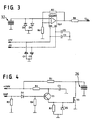
- the receiver electronics according to FIG. 4 are likewise integrated in the test head. It is respected on the shortest possible supply lines, these should less than 2 cm long, preferably shorter.
- the receiver electronics uses an op-amp Op1 CLC 449 from Comlinear, he is set to quadruple gain. He forms a high-impedance Termination of the receiver so as not to stress the receiving foil. In this way a Signalvermerschuug is avoided.
- the reinforcement is determined by the resistors R6 and R7.
- Op Amp is a cable driver for the subsequent 50 ohm coaxial cable for signal transmission of the output signal Usig.
- the two oscillators 26, 32 is in the receiver oscillator 32 an electrical crosstalk of the transmission signal.
- the anti-parallel connected Diodes D3 and D4 have the task of crosstalk too limit. At the same time they protect the op amp from being in to reach the saturation region.
- Transmitter electronics and receiver electronics are realized in SMD technology to minimize the size.
- the entire electronics finds it on a circuit board that has a size of 15mm x 32mm.
Landscapes
- Physics & Mathematics (AREA)
- General Physics & Mathematics (AREA)
- Engineering & Computer Science (AREA)
- Mechanical Engineering (AREA)
- Chemical & Material Sciences (AREA)
- Life Sciences & Earth Sciences (AREA)
- Health & Medical Sciences (AREA)
- Analytical Chemistry (AREA)
- Biochemistry (AREA)
- General Health & Medical Sciences (AREA)
- Immunology (AREA)
- Pathology (AREA)
- Investigating Or Analyzing Materials By The Use Of Ultrasonic Waves (AREA)
- Transducers For Ultrasonic Waves (AREA)
- Measurement Of Velocity Or Position Using Acoustic Or Ultrasonic Waves (AREA)
Abstract
Description
- FIG. 1:
- eine Seitenansicht in Explosionsdarstellung eines Prüfkopfes,
- FIG. 2:
- eine Seitenansicht eines Prüfkopfes in geänderter Ausführung,
- FIG. 3:
- ein elektronisches Schaltbild der Empfängerelektronik und
- FIG. 4:
- ein elektronisches Schaltbild der Senderelektronik.
Claims (10)
- Prüfkopf für die Ultraschallprüfung nach dem Impuls-Echo-Verfahren, insbesondere zur Erzeugung eines kurzzeitigen, möglichst unipolaren Ultraschallimpulses, mit einem Senderschwinger (26) und einem Empfängerschwinger (32), die jeweils mit Elektroden (28, 30, 34, 36) versehen sind, wobei der Senderschwinger (26) und der Empfängerschwinger (32) in Schallausbreitungsrichtung unmittelbar hintereinander angeordnet sind, dadurch gekennzeichnet, dass Senderschwinger (26) und Empfängerschwinger (32) aus dem gleichen Material gefertigt sind und jeweils aus Kunststofffolie hergestellt sind.
- Prüfkopf nach Anspruch 1, dadurch gekennzeichnet, dass Senderschwinger (26) und Empfängerschwinger (32) durch eine Klebschicht (48) miteinander verbunden sind, und dass die Dicke der Klebschicht (48) zwischen Senderschwinger (26) und Empfängerschwinger (32) möglichst gering ist, insbesondere wesentlich kleiner ist als die Wellenlänge, für die die Schwinger (26, 32) ausgelegt sind.
- Prüfkopf nach Anspruch 1, dadurch gekennzeichnet, dass der Senderschwinger (26) und der Empfängerschwinger (32) im Wesentlichen baugleich sind.
- Prüfkopf nach Anspruch 1, dadurch gekennzeichnet, dass der Senderschwinger (26) an seiner vom Empfängerschwinger (32) abgewandten Fläche mit einem Dämpfungskörper (24) verbunden ist.
- Prüfkopf nach Anspruch 1, dadurch gekennzeichnet, dass der Empfängerschwinger (32) an seiner vom Senderschwinger (26) abgewandten Fläche mit einem Vorlaufkörper (38) verbunden ist, insbesondere, dass ein Vorlaufkörper (38) verwendet wird, der nur wenige Millimeter dick ist, typischerweise zwischen 1 bis 4 mm dick, vorzugsweise 2 mm dick ist.
- Prüfkopf nach Anspruch 1, bei dem der Senderschwinger (26) mit einer Senderelektronik und der Empfängerschwinger (32) mit einer Empfängerelektronik verbunden ist, dadurch gekennzeichnet, dass die unmittelbar benachbarten, durch die Klebschicht (48) verbundenen Elektroden (28, 30, 34, 36) auf gleichem Potential liegen, insbesondere auf Massepotential liegen.
- Prüfkopf nach Anspruch 6 mit einem Prüfkopfgehäuse, dadurch gekennzeichnet, dass Senderelektronik und Empfängerelektronik so nah wie möglich an den Schwingern (26, 32) angeordnet sind, insbesondere sich in dem Gehäuse des Prüfkopfs befinden.
- Prüfkopf nach Anspruch 6, dadurch gekennzeichnet, dass der Senderschwinger (26) mit einem niederohmig ausgeführten Ausgang der Senderelektronik verbunden ist und dass der Empfängerschwinger (32) mit einem hochohmig ausgebildeten Empfängereingang verbunden ist.
- Prüfkopf nach Anspruch 1, dadurch gekennzeichnet, dass die Schwinger aus PVDF-Folien hergestellt sind.
- Verfahren zum Betreiben eines Prüfkopfes nach einem der vorangegangenen Patentansprüche, dadurch gekennzeichnet, dass zur Erzeugung der Anregungsspannung des Senderschwingers (26) an diesen eine zeitlich langsam ansteigende Spannung angelegt wird und nach Erreichen einer ausreichenden Spannung der Senderschwinger (26) anschließend möglichst in sehr kurzer Zeit kurzgeschlossen wird.
Applications Claiming Priority (3)
| Application Number | Priority Date | Filing Date | Title |
|---|---|---|---|
| DE19735101 | 1997-08-13 | ||
| DE19735101A DE19735101A1 (de) | 1997-08-13 | 1997-08-13 | Prüfkopf für die Ultraschallprüfung nach dem Impuls-Echo-Verfahren |
| PCT/DE1998/001323 WO1999008809A1 (de) | 1997-08-13 | 1998-05-13 | Prüfkopf für die ultraschallprüfung nach dem impuls-echo-verfahren |
Publications (3)
| Publication Number | Publication Date |
|---|---|
| EP1003614A1 EP1003614A1 (de) | 2000-05-31 |
| EP1003614B1 true EP1003614B1 (de) | 2005-08-10 |
| EP1003614B8 EP1003614B8 (de) | 2005-10-12 |
Family
ID=7838867
Family Applications (1)
| Application Number | Title | Priority Date | Filing Date |
|---|---|---|---|
| EP98933515A Expired - Lifetime EP1003614B8 (de) | 1997-08-13 | 1998-05-13 | Prüfkopf für die ultraschallprüfung nach dem impuls-echo-verfahren |
Country Status (9)
| Country | Link |
|---|---|
| US (1) | US6286371B1 (de) |
| EP (1) | EP1003614B8 (de) |
| JP (1) | JP4197577B2 (de) |
| KR (1) | KR20010022692A (de) |
| AU (1) | AU8332098A (de) |
| CA (1) | CA2300091C (de) |
| DE (2) | DE19735101A1 (de) |
| IL (1) | IL134209A (de) |
| WO (1) | WO1999008809A1 (de) |
Families Citing this family (4)
| Publication number | Priority date | Publication date | Assignee | Title |
|---|---|---|---|---|
| AU2003222969A1 (en) * | 2002-04-12 | 2003-10-27 | Azea Networks Limited | Transmission system |
| RU2248850C1 (ru) * | 2004-06-21 | 2005-03-27 | Общество с ограниченной ответственностью "Ультразвуковая техника - инлаб" | Ультразвуковое устройство |
| US8007659B2 (en) | 2008-06-03 | 2011-08-30 | Graftech International Holdings Inc. | Reduced puffing needle coke from coal tar distillate |
| WO2016148860A1 (en) * | 2015-03-16 | 2016-09-22 | The Regents Of The University Of California | Ultrasonic microphone and ultrasonic acoustic radio |
Family Cites Families (11)
| Publication number | Priority date | Publication date | Assignee | Title |
|---|---|---|---|---|
| JPS5728500A (en) * | 1980-07-29 | 1982-02-16 | Kureha Chem Ind Co Ltd | Ultrasonic wave transducer |
| FR2496919A1 (fr) * | 1980-12-22 | 1982-06-25 | Labo Electronique Physique | Appareil d'examen de milieux par methode ultrasonore |
| JPS6066882A (ja) * | 1983-09-22 | 1985-04-17 | Murata Mfg Co Ltd | 圧電変位素子およびその分極方法 |
| DE3441563A1 (de) | 1984-11-14 | 1985-05-30 | Michael Dipl.-Phys. 5600 Wuppertal Platte | Kombinierte ultraschallwandler aus keramischen und hochpolymeren piezoelektrischen materialien |
| JPS61205100A (ja) * | 1985-03-08 | 1986-09-11 | Murata Mfg Co Ltd | 圧電発音体 |
| DE3710339A1 (de) * | 1987-03-28 | 1988-10-06 | Deutsch Pruef Messgeraete | Piezopolymerer ultraschallwandler |
| US4868447A (en) * | 1987-09-11 | 1989-09-19 | Cornell Research Foundation, Inc. | Piezoelectric polymer laminates for torsional and bending modal control |
| JP3039971B2 (ja) * | 1989-09-19 | 2000-05-08 | 株式会社日立製作所 | 接合型圧電装置及び製造方法並びに接合型圧電素子 |
| JP3185226B2 (ja) * | 1991-01-30 | 2001-07-09 | 株式会社村田製作所 | 圧電バイモルフ素子の駆動方法及び圧電バイモルフ素子 |
| JPH0773732A (ja) * | 1993-06-23 | 1995-03-17 | Sharp Corp | 誘電体薄膜素子及びその製造方法 |
| US5629906A (en) * | 1995-02-15 | 1997-05-13 | Hewlett-Packard Company | Ultrasonic transducer |
-
1997
- 1997-08-13 DE DE19735101A patent/DE19735101A1/de not_active Ceased
-
1998
- 1998-05-13 IL IL13420998A patent/IL134209A/xx not_active IP Right Cessation
- 1998-05-13 CA CA002300091A patent/CA2300091C/en not_active Expired - Fee Related
- 1998-05-13 US US09/485,496 patent/US6286371B1/en not_active Expired - Lifetime
- 1998-05-13 AU AU83320/98A patent/AU8332098A/en not_active Abandoned
- 1998-05-13 JP JP2000509535A patent/JP4197577B2/ja not_active Expired - Fee Related
- 1998-05-13 DE DE59812997T patent/DE59812997D1/de not_active Expired - Lifetime
- 1998-05-13 EP EP98933515A patent/EP1003614B8/de not_active Expired - Lifetime
- 1998-05-13 KR KR1020007001287A patent/KR20010022692A/ko not_active Withdrawn
- 1998-05-13 WO PCT/DE1998/001323 patent/WO1999008809A1/de not_active Ceased
Also Published As
| Publication number | Publication date |
|---|---|
| AU8332098A (en) | 1999-03-08 |
| IL134209A (en) | 2003-04-10 |
| IL134209A0 (en) | 2001-04-30 |
| WO1999008809A1 (de) | 1999-02-25 |
| EP1003614B8 (de) | 2005-10-12 |
| DE59812997D1 (de) | 2005-09-15 |
| EP1003614A1 (de) | 2000-05-31 |
| CA2300091C (en) | 2005-02-08 |
| JP4197577B2 (ja) | 2008-12-17 |
| DE19735101A1 (de) | 1999-02-18 |
| US6286371B1 (en) | 2001-09-11 |
| JP2001515214A (ja) | 2001-09-18 |
| KR20010022692A (ko) | 2001-03-26 |
| CA2300091A1 (en) | 1999-02-25 |
Similar Documents
| Publication | Publication Date | Title |
|---|---|---|
| DE2512494C2 (de) | ||
| EP0547060B1 (de) | Ultraschallwandler für die laufzeitmessung von ultraschall-impulsen in einem gas | |
| EP0017216B1 (de) | Ultraschallwandler | |
| DE3390293T1 (de) | Ultraschallwandler | |
| DE4008768A1 (de) | Piezoelektrischer wandler | |
| DE102008041835A1 (de) | Impulsechoverfahren mittels Gruppenstrahler und Temperaturkompensation | |
| EP0040375A1 (de) | Ultraschallwandleranordnung | |
| DE2202989A1 (de) | Fokussierter ultraschallwandler | |
| EP1003614B1 (de) | Prüfkopf für die ultraschallprüfung nach dem impuls-echo-verfahren | |
| DE3924919C2 (de) | ||
| DE3206111A1 (de) | Wandler mit verbesserter aufloesung systeme und verfahren fuer die aussendung und/oder den empfang von durch schwingungen ausgebteiteten wellen | |
| DE29916826U1 (de) | Vorrichtung zum Messen der spezifischen Dichte eines gasförmigen oder flüssigen Mediums | |
| EP0600911B1 (de) | Messverfahren für die schleimhautdicke eines kieferknochenkamms | |
| DE19937479A1 (de) | Ultraschall-Sensoranordnung | |
| EP0086531B1 (de) | Anordnung zur Untersuchung mit Ultraschall | |
| CH456191A (de) | Verfahren zur Temperaturmessung und Einrichtung zur Ausführung des Verfahrens | |
| DE2708226A1 (de) | Sende- und empfangswandler fuer ultraschall-strahlung, geeignet fuer grossen entfernungsbereich | |
| DE3720574C2 (de) | ||
| Felix et al. | High bandwidth, high density arrays for advanced ultrasound imaging | |
| EP3265763B1 (de) | Schallwandler zum empfangen von wasserschallwellen, wandlervorrichtung, sonar und wasserfahrzeug | |
| DE3401979A1 (de) | Ultraschall-wandler | |
| DE3221209C2 (de) | Gerät zur Untersuchung von Körpern durch Abtastung mittels Ultraschall | |
| DE102018119206A1 (de) | Verfahren zum Erfassen der Geometrie eines Bereichs eines Gegenstandes mittels Ultraschall | |
| Johnson et al. | Studies of the Otic Capsule: I. Reduced Dead Time Ultrasonic Probe for Measurement of Bone Thickness | |
| DE1013898B (de) | Ultraschallschwingeranordnung zur zerstoerungsfreien Werkstoffpruefung mittels Ultraschallimpulsen |
Legal Events
| Date | Code | Title | Description |
|---|---|---|---|
| PUAI | Public reference made under article 153(3) epc to a published international application that has entered the european phase |
Free format text: ORIGINAL CODE: 0009012 |
|
| 17P | Request for examination filed |
Effective date: 20000313 |
|
| AK | Designated contracting states |
Kind code of ref document: A1 Designated state(s): CH DE FR GB IT LI |
|
| 17Q | First examination report despatched |
Effective date: 20040525 |
|
| GRAP | Despatch of communication of intention to grant a patent |
Free format text: ORIGINAL CODE: EPIDOSNIGR1 |
|
| GRAS | Grant fee paid |
Free format text: ORIGINAL CODE: EPIDOSNIGR3 |
|
| GRAA | (expected) grant |
Free format text: ORIGINAL CODE: 0009210 |
|
| AK | Designated contracting states |
Kind code of ref document: B1 Designated state(s): CH DE FR GB IT LI |
|
| PG25 | Lapsed in a contracting state [announced via postgrant information from national office to epo] |
Ref country code: IT Free format text: LAPSE BECAUSE OF FAILURE TO SUBMIT A TRANSLATION OF THE DESCRIPTION OR TO PAY THE FEE WITHIN THE PRESCRIBED TIME-LIMIT;WARNING: LAPSES OF ITALIAN PATENTS WITH EFFECTIVE DATE BEFORE 2007 MAY HAVE OCCURRED AT ANY TIME BEFORE 2007. THE CORRECT EFFECTIVE DATE MAY BE DIFFERENT FROM THE ONE RECORDED. Effective date: 20050810 |
|
| REG | Reference to a national code |
Ref country code: GB Ref legal event code: FG4D Free format text: NOT ENGLISH |
|
| REG | Reference to a national code |
Ref country code: CH Ref legal event code: EP |
|
| REF | Corresponds to: |
Ref document number: 59812997 Country of ref document: DE Date of ref document: 20050915 Kind code of ref document: P |
|
| RAP2 | Party data changed (patent owner data changed or rights of a patent transferred) |
Owner name: GE INSPECTION TECHNOLOGIES GMBH |
|
| GBT | Gb: translation of ep patent filed (gb section 77(6)(a)/1977) |
Effective date: 20060206 |
|
| ET | Fr: translation filed | ||
| PLBE | No opposition filed within time limit |
Free format text: ORIGINAL CODE: 0009261 |
|
| STAA | Information on the status of an ep patent application or granted ep patent |
Free format text: STATUS: NO OPPOSITION FILED WITHIN TIME LIMIT |
|
| 26N | No opposition filed |
Effective date: 20060511 |
|
| PGFP | Annual fee paid to national office [announced via postgrant information from national office to epo] |
Ref country code: CH Payment date: 20130530 Year of fee payment: 16 |
|
| PGFP | Annual fee paid to national office [announced via postgrant information from national office to epo] |
Ref country code: GB Payment date: 20140527 Year of fee payment: 17 |
|
| PGFP | Annual fee paid to national office [announced via postgrant information from national office to epo] |
Ref country code: FR Payment date: 20140519 Year of fee payment: 17 |
|
| REG | Reference to a national code |
Ref country code: CH Ref legal event code: PL |
|
| PG25 | Lapsed in a contracting state [announced via postgrant information from national office to epo] |
Ref country code: LI Free format text: LAPSE BECAUSE OF NON-PAYMENT OF DUE FEES Effective date: 20140531 Ref country code: CH Free format text: LAPSE BECAUSE OF NON-PAYMENT OF DUE FEES Effective date: 20140531 |
|
| GBPC | Gb: european patent ceased through non-payment of renewal fee |
Effective date: 20150513 |
|
| REG | Reference to a national code |
Ref country code: FR Ref legal event code: ST Effective date: 20160129 |
|
| PG25 | Lapsed in a contracting state [announced via postgrant information from national office to epo] |
Ref country code: GB Free format text: LAPSE BECAUSE OF NON-PAYMENT OF DUE FEES Effective date: 20150513 |
|
| PG25 | Lapsed in a contracting state [announced via postgrant information from national office to epo] |
Ref country code: FR Free format text: LAPSE BECAUSE OF NON-PAYMENT OF DUE FEES Effective date: 20150601 |
|
| PGFP | Annual fee paid to national office [announced via postgrant information from national office to epo] |
Ref country code: DE Payment date: 20160527 Year of fee payment: 19 |
|
| REG | Reference to a national code |
Ref country code: DE Ref legal event code: R119 Ref document number: 59812997 Country of ref document: DE |
|
| PG25 | Lapsed in a contracting state [announced via postgrant information from national office to epo] |
Ref country code: DE Free format text: LAPSE BECAUSE OF NON-PAYMENT OF DUE FEES Effective date: 20171201 |