EP1004799B1 - Engrenage différentiel avec couvercle refroidisseur - Google Patents
Engrenage différentiel avec couvercle refroidisseur Download PDFInfo
- Publication number
- EP1004799B1 EP1004799B1 EP19990123312 EP99123312A EP1004799B1 EP 1004799 B1 EP1004799 B1 EP 1004799B1 EP 19990123312 EP19990123312 EP 19990123312 EP 99123312 A EP99123312 A EP 99123312A EP 1004799 B1 EP1004799 B1 EP 1004799B1
- Authority
- EP
- European Patent Office
- Prior art keywords
- lubricant
- conduits
- final drive
- drive unit
- rotatable member
- Prior art date
- Legal status (The legal status is an assumption and is not a legal conclusion. Google has not performed a legal analysis and makes no representation as to the accuracy of the status listed.)
- Expired - Lifetime
Links
Images

Classifications
-
- F—MECHANICAL ENGINEERING; LIGHTING; HEATING; WEAPONS; BLASTING
- F16—ENGINEERING ELEMENTS AND UNITS; GENERAL MEASURES FOR PRODUCING AND MAINTAINING EFFECTIVE FUNCTIONING OF MACHINES OR INSTALLATIONS; THERMAL INSULATION IN GENERAL
- F16H—GEARING
- F16H57/00—General details of gearing
- F16H57/04—Features relating to lubrication or cooling or heating
- F16H57/048—Type of gearings to be lubricated, cooled or heated
- F16H57/0482—Gearings with gears having orbital motion
- F16H57/0483—Axle or inter-axle differentials
-
- F—MECHANICAL ENGINEERING; LIGHTING; HEATING; WEAPONS; BLASTING
- F16—ENGINEERING ELEMENTS AND UNITS; GENERAL MEASURES FOR PRODUCING AND MAINTAINING EFFECTIVE FUNCTIONING OF MACHINES OR INSTALLATIONS; THERMAL INSULATION IN GENERAL
- F16H—GEARING
- F16H57/00—General details of gearing
- F16H57/04—Features relating to lubrication or cooling or heating
- F16H57/0412—Cooling or heating; Control of temperature
- F16H57/0415—Air cooling or ventilation; Heat exchangers; Thermal insulations
- F16H57/0416—Air cooling or ventilation
-
- F—MECHANICAL ENGINEERING; LIGHTING; HEATING; WEAPONS; BLASTING
- F16—ENGINEERING ELEMENTS AND UNITS; GENERAL MEASURES FOR PRODUCING AND MAINTAINING EFFECTIVE FUNCTIONING OF MACHINES OR INSTALLATIONS; THERMAL INSULATION IN GENERAL
- F16H—GEARING
- F16H57/00—General details of gearing
- F16H57/04—Features relating to lubrication or cooling or heating
- F16H57/0457—Splash lubrication
-
- F—MECHANICAL ENGINEERING; LIGHTING; HEATING; WEAPONS; BLASTING
- F16—ENGINEERING ELEMENTS AND UNITS; GENERAL MEASURES FOR PRODUCING AND MAINTAINING EFFECTIVE FUNCTIONING OF MACHINES OR INSTALLATIONS; THERMAL INSULATION IN GENERAL
- F16H—GEARING
- F16H57/00—General details of gearing
- F16H57/02—Gearboxes; Mounting gearing therein
- F16H57/031—Gearboxes; Mounting gearing therein characterised by covers or lids for gearboxes
-
- Y—GENERAL TAGGING OF NEW TECHNOLOGICAL DEVELOPMENTS; GENERAL TAGGING OF CROSS-SECTIONAL TECHNOLOGIES SPANNING OVER SEVERAL SECTIONS OF THE IPC; TECHNICAL SUBJECTS COVERED BY FORMER USPC CROSS-REFERENCE ART COLLECTIONS [XRACs] AND DIGESTS
- Y10—TECHNICAL SUBJECTS COVERED BY FORMER USPC
- Y10T—TECHNICAL SUBJECTS COVERED BY FORMER US CLASSIFICATION
- Y10T74/00—Machine element or mechanism
- Y10T74/21—Elements
- Y10T74/2186—Gear casings
- Y10T74/2189—Cooling
Definitions
- This invention relates generally to an automotive drive unit and more particularly to an automotive final drive unit with a lubricant cooling cover.
- the rear wheels of a rear drive automobile are driven by a final drive unit that splits the torque received from a longitudinal propeller shaft between the two rear wheels by means of a differential gear set inside a gear housing of the final drive unit.
- the propeller shaft drives an internal pinion gear that drives an internal ring gear attached to a rotary differential case.
- the differential case supports equalizing gears that drive two side gears that are attached to drive shafts that are connected to the respective rear wheels.
- the bottom of the gear housing is a reservoir that is filled with lubricant that is distributed to the various differential gears during operation of the final drive unit.
- This lubricant can become quite hot. Consequently, a final drive unit often has lubricant cooling provisions.
- U.S. Patent 5,540,300 granted July 30, 1996 discloses an axle that includes a final drive unit that has a gear housing and a cover attached to the gear housing forming a lubricant reservoir.
- the final drive unit includes a rotatable member forming part of a gear assembly that is rotatably mounted in the gear housing with a lower portion of the rotatable member immersed in the lubricant reservoir.
- the axle has a lubricant cooling system which comprises a lubricant cooling passage in the cover in fluid communication with the lubricant reservoir via an inlet that is exposed to lubricant in the lubricant reservoir.
- the inlet is disposed with respect to the rotatable member so that lubricant flows into the lubricant passage when the rotatable member rotates.
- the lubricant passage is connected to outlets located above the inlet and the lubricant in the lubricant reservoir.
- This invention provides a final drive unit having a cover that provides an improved lubricant cooling arrangement.
- the cover has a lubricant cooling passage that divides the lubricant delivered by a rotatable member forming part of a gear assembly amongst several parallel lubricant cooling conduits.
- the cover may have an inner part and an outer part that may be shells.
- the several parallel lubricant cooling conduits that are preferably partially formed by embossments in an outer shell of the cover to increase the wall area of the lubricant cooling conduits that is exposed to cooling ambient air.
- the several parallel lubricant cooling conduits may be configured to equalize flow rates through the several lubricant cooling conduits.
- a final drive unit 10 of the invention comprises a gear housing 12, a differential gear assembly 14 that is rotatably mounted in the gear housing 12 and a removable cover 16.
- the gear housing 12 has journal openings 18 and 20 in opposite sides of the gear housing 12. These journal openings include bearing seats for rotatably mounting the differential gear assembly 14 inside the gear housing 12 as best shown in figure 2.
- the differential gear assembly 14 is drivingly connected to an engine driven propeller shaft (not shown) by a rotary stub shaft 22 that extends through a journal opening in the front of the gear housing 12 (not shown).
- Stub shaft 22 has a yoke 24 at the outside end for connecting the stub shaft 22 to the propeller shaft by a conventional Cardan type universal joint (not shown).
- Stub shaft 22 has a pinion gear 26 at the inside end that drives a ring gear 28 of the rotary differential gear assembly 14.
- the differential gear assembly 14 is a conventional bevel gear differential of the type that is customarily used in automotive final drives, particularly in final rear drives.
- a bevel gear differential operates in a well known manner so that its operation need not be described in detail for those skilled in the art to understand the invention. Suffice it to say that the ring gear 28 is attached to and rotates a differential case 30 in one direction or the other whenever the vehicle is in motion.
- the rotary differential case 30 houses equalizing gears that mesh with side gears that are attached to the inner ends of drive shafts 31.
- the differential gear assembly 14 is installed in the gear housing 12 through a large rear opening that is conventionally closed by a removable cover after the differential gear assembly 14 is installed.
- the removable cover 16 of final drive unit 10 provides an improved lubricant cooling arrangement as explained below.
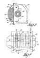
- a lubricant reservoir 32 is formed inside the gear housing 12. This reservoir is filled with lubricant 34 to a predetermined fill level so that ring gear 28 forming part of the rotary differential assembly 14 is partially emersed in lubricant 34 is lubricant reservoir 32 as best shown in figure 3.
- the meshing gears of the differential gear assembly 14 are constantly rotating when the vehicle is in motion, particularly the ring gear 28 and the pinion gear 26 that drives ring gear 28. This constant working of the meshing gears during vehicle operation, along with other internal frictions, produces heat that raises the temperature of lubricant 34 in lubricant reservoir 32.
- the final drive unit 10 of the invention includes a lubricant cooling system that reduces operating temperature of lubricant 34.
- This lubricant cooling system comprises a lubricant cooling passage that is formed in removable cover 16.
- Cover 16 comprises an outer member that is preferably a shell 36 that is fastened to gear housing 12 and an inner member that is also preferably a shell 38.
- Inner shell 38 nests in the outer shell 36 as best shown in figure 2.
- Outer shell 36 has a peripheral wall 39 and several lands 40 that engage inner shell 38 (figure 3) and a fork-like embossment 42 (figure 4) that cooperate with inner shell 38 to form the lubricant cooling passage of the invention.
- the lubricant cooling passage commences with an inlet 44 that is aligned with rotary ring gear 28 so that ring gear 28 pushes lubricant into the cooling passage via inlet 44 as indicated by the arrows 46 when ring gear 28 rotates in the clockwise direction as viewed in figure 3.
- Inlet 44 is preferably as near the bottom of cover 16 as possible.
- Manifold 48 communicates with a horizontal manifold 48.
- Manifold 48 is just above inlet 44 and preferably extends for substantially the entire width of the drive unit 10 as best shown in figure 4.
- Manifold 48 in turn communicates with a plurality of laterally spaced, vertical conduits 50, 52, 53.
- Vertical conduits 50, 52, 53 are preferably all spaced laterally of ring gear 28 while vertical conduits 50 on either side of ring gear 28 preferably have a smaller cross section than intermediate conduits 52.
- End conduits 53 also preferably have a larger cross section than intermediate conduits 52.
- Vertical conduits 50, 52, 53 each extend from manifold 48 to an outlet 54 that is located well above inlet 44, manifold 48 and the lubricant 34 in reservoir 32.
- Outlets 54 are preferably located above axis 55 of the differential gear assembly 14 and as high as possible without restricting flow through the outlets to any appreciable degree so as to maximize their height and consequently the cooling effect of vertical conduits 50, 52, 53.
- ring gear 28 pushes lubricant from reservoir 32 into the lubricant cooling passage via inlet 44 where the manifold 48 of the lubricant cooling passage divides the lubricant 32 amongst the several vertical conduits 50, 52, 53 of the lubricant cooling passage.
- Lubricant flows up conduits 50, 52, 53 and out through several outlets 54 and then returns to reservoir 32 by gravity flow.
- the majority of the manifold 48 and the conduits 50, 52, 53 forming the lubricant cooling passage of the invention are formed by walls constituting part of the fork-like embossment 42 of the outer shell 36.
- the hot lubricant is not only divided into smaller parcels for cooling but the hot lubricant also flows through a lubricant cooling passage that is mostly exposed to ambient cooling air for improved heat transfer by conduction.
- the removable cover 16 provides a very efficient radiator for cooling the lubricant in drive unit 10.
- the cooling can be further enhanced by incorporating optional cooling fins 56 on the exterior of outer shell 36 that extend crosswise of the vertical cooling conduits 50, 52, 53 as shown in figure 4. Any number of vertically spaced cooling fins 56 can be used.
- the shells 36 and 38 of cover 16 may be a steel or aluminum sheet metal stamping or an aluminum or aluminum alloy casting.
- the removable cover 16 of the invention with its improved cooling arrangement has been illustrated in conjunction with a final drive unit 10 of the type that is used in independent suspensions.
- the removable cover 16 of the invention is particularly useful in such a drive unit because of a heat transfer area limited to the confines of the gear housing 12 and cover 16.
- the removable cover of the invention can also be used with final drive units that are part of an axle assembly that includes axle tubes extending out the sides of the gear housing that can also be used for heat transfer.
Landscapes
- Engineering & Computer Science (AREA)
- General Engineering & Computer Science (AREA)
- Mechanical Engineering (AREA)
- General Details Of Gearings (AREA)
Claims (10)
- Engrenage différentiel arrière ayant un carter (12) d'engrenages, un couvercle (16) fixé au carter d'engrenages formant un réservoir (32) à lubrifiant dans le carter d'engrenages, un élément rotatif (14) faisant partie d'un assemblage d'engrenages monté rotatif dans le carter d'engrenages, l'élément rotatif ayant une portion inférieure qui est immergée dans le lubrifiant dans le réservoir à lubrifiant et un système de refroidissement du lubrifiant qui comprend un passage de refroidissement du lubrifiant dans le couvercle en communication fluidique avec le réservoir à lubrifiant via une entrée (44) qui est exposée au lubrifiant dans le réservoir à lubrifiant, l'entrée étant disposée par rapport à l'élément rotatif de telle sorte que le lubrifiant s'écoule dans le passage de refroidissement du lubrifiant lorsque l'élément rotatif tourne, et le passage pour le lubrifiant étant relié à des sorties (54) situées au-dessus de ladite entrée et du lubrifiant dans ledit réservoir à lubrifiant, caractérisé en ce que :
le passage de refroidissement du lubrifiant comprend un collecteur (48) et une pluralité de conduits parallèles (50, 52, 53) qui sont reliés au collecteur et qui ont des sorties respectives qui sont situées au-dessus de l'entrée et du lubrifiant dans ledit réservoir à lubrifiant, ce qui fait que le lubrifiant s'écoulant dans le passage de refroidissement pour le lubrifiant est divisé entre la pluralité de conduits parallèles avant que le lubrifiant soit renvoyé au réservoir (32) via lesdites sorties. - Engrenage différentiel arrière selon la revendication 1, dans lequel le collecteur (48) est situé juste au-dessus de l'entrée (44).
- Engrenage différentiel arrière selon la revendication 1 ou 2, dans lequel tous les conduits parallèles (50, 52, 53) sont écartés latéralement de l'élément rotatif (14).
- Engrenage différentiel arrière selon la revendication 3, dans lequel le couvercle (16) possède un élément extérieur (36) et un élément intérieur (38).
- Engrenage différentiel arrière selon la revendication 4, dans lequel le collecteur (48) et les conduits (50, 52, 53) sont partiellement formés dans les éléments extérieurs (36).
- Engrenage différentiel arrière selon la revendication 4, dans lequel les conduits (50) de part et d'autre de l'élément rotatif (14) ont une section transversale plus petite que le reste des conduits (52, 53).
- Engrenage différentiel arrière selon la revendication 4, dans lequel les conduits comprennent une première paire de conduits (50) situés de part et d'autre de l'élément rotatif, un second jeu de conduits (53) aux extrémités respectives du couvercle et au moins un conduit intermédiaire (52) qui a une section transversale, la première paire de conduits (50) ayant une section transversale plus petite que la section transversale du conduit intermédiaire (52) et le second jeu de conduits (53) ayant une section transversale qui est supérieure à la section transversale du conduit intermédiaire (52).
- Engrenage différentiel arrière selon la revendication 4, dans lequel l'élément intérieur (38) et élément extérieur (36) sont des enveloppes.
- Engrenage différentiel arrière selon la revendication 8, dans lequel l'enveloppe extérieure (36) possède une pluralité d'ailettes de refroidissement (56) qui s'étendent transversalement aux conduits.
- Engrenage différentiel arrière selon l'une quelconque des revendications précédentes, dans lequel les sorties sont situées au-dessus de l'axe (55) de l'élément rotatif (14).
Applications Claiming Priority (2)
| Application Number | Priority Date | Filing Date | Title |
|---|---|---|---|
| US09/197,779 US6155135A (en) | 1998-11-23 | 1998-11-23 | Drive unit with lubricant cooling cover |
| US197779 | 1998-11-23 |
Publications (3)
| Publication Number | Publication Date |
|---|---|
| EP1004799A2 EP1004799A2 (fr) | 2000-05-31 |
| EP1004799A3 EP1004799A3 (fr) | 2000-10-18 |
| EP1004799B1 true EP1004799B1 (fr) | 2003-08-06 |
Family
ID=22730733
Family Applications (1)
| Application Number | Title | Priority Date | Filing Date |
|---|---|---|---|
| EP19990123312 Expired - Lifetime EP1004799B1 (fr) | 1998-11-23 | 1999-11-22 | Engrenage différentiel avec couvercle refroidisseur |
Country Status (5)
| Country | Link |
|---|---|
| US (1) | US6155135A (fr) |
| EP (1) | EP1004799B1 (fr) |
| CA (1) | CA2290262A1 (fr) |
| DE (1) | DE69910153T2 (fr) |
| ES (1) | ES2205684T3 (fr) |
Families Citing this family (26)
| Publication number | Priority date | Publication date | Assignee | Title |
|---|---|---|---|---|
| US6499565B1 (en) * | 2000-03-15 | 2002-12-31 | Case Corporation | Apparatus and method for cooling an axle |
| US6997238B1 (en) * | 2001-02-27 | 2006-02-14 | W.S. Darley & Co. | Cooler plate and gearbox assembly |
| US6997284B1 (en) | 2001-06-26 | 2006-02-14 | Spicer Technology, Inc. | Lubricant cooling system for a motor vehicle axle |
| US6675676B2 (en) | 2001-12-14 | 2004-01-13 | Americam Axle & Manufacturing, Inc. | Differential cover for a vehicle that provides uniform sealing |
| US20050126749A1 (en) * | 2002-05-14 | 2005-06-16 | Matti Assil I. | Heat pipe cooler for differential assembly |
| DE10255720B4 (de) * | 2002-11-29 | 2005-07-28 | Audi Ag | Differential für Kraftfahrzeuge |
| US7004879B2 (en) * | 2004-01-12 | 2006-02-28 | American Axle & Manufacturing, Inc. | Axle differential with stamped carrier cover pan |
| US7188699B2 (en) * | 2004-02-11 | 2007-03-13 | American Axle & Manufacturing, Inc. | Axle assembly with cooling pump |
| DE102004022863B4 (de) * | 2004-05-06 | 2010-08-05 | Sew-Eurodrive Gmbh & Co. Kg | Getriebe |
| US7374507B2 (en) * | 2006-02-13 | 2008-05-20 | Ford Motor Company | Lubrication system for differential mechanism |
| US7465158B2 (en) * | 2006-04-04 | 2008-12-16 | Bevan Weston | Reduction gear pump |
| DE102006020801B4 (de) * | 2006-05-03 | 2025-05-08 | Sew-Eurodrive Gmbh & Co Kg | Kühlmodul für ein Getriebe, Getriebe mit Kühlvorrichtung und Baukasten für Getriebekühlvorrichtungen |
| GB2471651A (en) | 2009-06-30 | 2011-01-12 | Meritor Technology Inc | Axle crown wheel housing with nested bowls defining a reservoir |
| US8707826B2 (en) * | 2010-01-05 | 2014-04-29 | Chrysler Group Llc | Axle with variable volume sump |
| US9599406B2 (en) * | 2010-01-27 | 2017-03-21 | Rexnord Industries, Llc | Transmission having a fluid cooling shroud |
| US8475314B2 (en) * | 2010-01-28 | 2013-07-02 | American Axle & Manufacturing, Inc. | Differential assembly with features for improved lubrication |
| US20120230843A1 (en) * | 2011-03-07 | 2012-09-13 | Caterpillar Inc. | Cooling system for an electric drive machine and method |
| US20140260788A1 (en) * | 2011-10-05 | 2014-09-18 | Schaeffler Technologies Gmbh & Co. Kg | Gearbox device with cooled dry-sump area |
| US8813609B1 (en) * | 2013-03-04 | 2014-08-26 | Gm Global Technology Operations, Llc | System for de-aerating fluid in a transmission |
| US9140349B1 (en) | 2014-04-23 | 2015-09-22 | American Axle & Manufacturing, Inc. | Compact axle assembly with locking differential |
| DE102016206841B3 (de) | 2016-04-22 | 2017-07-13 | Audi Ag | Antriebskomponente für ein Kraftfahrzeug sowie Kraftfahrzeug |
| US10876800B2 (en) * | 2018-07-12 | 2020-12-29 | Abb Schweiz Ag | Mechanical system with cooling apparatus |
| US10443705B1 (en) * | 2018-10-23 | 2019-10-15 | Gale C. Banks, III | Differential cover |
| US11378176B2 (en) * | 2019-12-13 | 2022-07-05 | Verlyn Ray Fast | Devices, systems, and methods for differential lubrication |
| US20260063197A1 (en) * | 2024-08-28 | 2026-03-05 | American Axle & Manufacturing, Inc. | Active cooling system |
| US12313156B1 (en) | 2024-10-25 | 2025-05-27 | Gale C. Banks, III | Transmission cooling system |
Family Cites Families (13)
| Publication number | Priority date | Publication date | Assignee | Title |
|---|---|---|---|---|
| US1318706A (en) * | 1919-10-14 | Willakd e | ||
| US2147391A (en) * | 1935-10-15 | 1939-02-14 | Cleveland Worm And Gear Compan | Reduction gear |
| US4002200A (en) * | 1972-12-07 | 1977-01-11 | Dean Products, Inc. | Extended fin heat exchanger panel |
| AT345051B (de) * | 1974-08-07 | 1978-08-25 | Louis Joerg Ges M B H | Einrichtung zum kuehlen eines schmiermittelgefuellten, mit kuehlrippen versehenen getriebegehaeuses mittels eines angebauten ventilators |
| US4235287A (en) * | 1975-05-02 | 1980-11-25 | Olin Corporation | Heat exchange panel |
| GB2103301A (en) | 1981-06-11 | 1983-02-16 | Gkn Axles | Cooling axle lubricants |
| DE3606963A1 (de) * | 1985-03-15 | 1986-09-25 | Zahnradfabrik Friedrichshafen Ag, 7990 Friedrichshafen | Maschinengehaeusemantel als oelkuehler |
| SE455716B (sv) * | 1987-02-24 | 1988-08-01 | Hypeco Ab | Vermevexlingsanordning for kylning av en maskin |
| DE4011022A1 (de) * | 1989-04-08 | 1990-10-11 | Zahnradfabrik Friedrichshafen | Triebachse |
| WO1991004427A1 (fr) * | 1989-09-23 | 1991-04-04 | Zahnradfabrik Friedrichshafen Ag | Carter de boite de vitesses |
| US4932469A (en) * | 1989-10-04 | 1990-06-12 | Blackstone Corporation | Automotive condenser |
| US5540300A (en) * | 1995-01-09 | 1996-07-30 | American Axle & Manufacturing Inc. | Drive axle assembly with lubricant cooling system |
| US5737922A (en) * | 1995-01-30 | 1998-04-14 | Aerojet General Corporation | Convectively cooled liner for a combustor |
-
1998
- 1998-11-23 US US09/197,779 patent/US6155135A/en not_active Expired - Lifetime
-
1999
- 1999-11-22 CA CA002290262A patent/CA2290262A1/fr not_active Abandoned
- 1999-11-22 DE DE1999610153 patent/DE69910153T2/de not_active Expired - Fee Related
- 1999-11-22 EP EP19990123312 patent/EP1004799B1/fr not_active Expired - Lifetime
- 1999-11-22 ES ES99123312T patent/ES2205684T3/es not_active Expired - Lifetime
Also Published As
| Publication number | Publication date |
|---|---|
| EP1004799A2 (fr) | 2000-05-31 |
| CA2290262A1 (fr) | 2000-05-23 |
| DE69910153D1 (de) | 2003-09-11 |
| US6155135A (en) | 2000-12-05 |
| DE69910153T2 (de) | 2004-06-09 |
| ES2205684T3 (es) | 2004-05-01 |
| EP1004799A3 (fr) | 2000-10-18 |
Similar Documents
| Publication | Publication Date | Title |
|---|---|---|
| EP1004799B1 (fr) | Engrenage différentiel avec couvercle refroidisseur | |
| US5540300A (en) | Drive axle assembly with lubricant cooling system | |
| US5839327A (en) | Drive axle assembly with lubricant cooling system | |
| US5316106A (en) | Lubricant cooling system for a motor vehicle axle | |
| US6997284B1 (en) | Lubricant cooling system for a motor vehicle axle | |
| US6432018B1 (en) | Integrated heat exchange circuit for an axle | |
| MXPA96004141A (en) | Assembly of impulsor axis with lubricating cooling system | |
| US8585526B2 (en) | Vehicle driveline component having heat sink for increased heat rejection capabilities | |
| WO2009088795A1 (fr) | Ensemble d'essieu ayant un ensemble de boîtier d'essieu comprenant des prises d'air de refroidissement | |
| US4947931A (en) | Plastic vehicular radiator-condenser with metal cooling inserts | |
| KR100317090B1 (ko) | 4륜구동차의동력전달장치 | |
| US7819769B2 (en) | Vehicle driveline component having heat sink for increased heat rejection capabilities | |
| JPH074590A (ja) | 歯車装置用潤滑剤再調質装置 | |
| CN106104084A (zh) | 动力传输单元 | |
| RU2158686C2 (ru) | Приводной агрегат, в частности, для автомобиля | |
| JPH08247260A (ja) | 差動装置の潤滑構造 | |
| JPH10138774A (ja) | 自動車におけるトランスファのブリーザ装置 | |
| EP1505312B1 (fr) | Dispositif de suppression de vibrations d'une groupe motopropulseur et procédé de suppression de vibrations pour une groupe motopropulseur | |
| CN207660664U (zh) | 油底壳、发动机和车辆 | |
| MXPA99010803A (es) | Unidad motriz con cubierta de enfriamiento de lubricante | |
| JPH10272944A (ja) | 4輪駆動車のトランスファ構造 | |
| JPH0633240Y2 (ja) | 4輪駆動車のトランスファ構造 | |
| CN118242426B (zh) | 驱动桥的润滑结构及车辆 | |
| JP2007064318A (ja) | 動力分配装置 | |
| JP3722095B2 (ja) | 四輪駆動車の駆動装置 |
Legal Events
| Date | Code | Title | Description |
|---|---|---|---|
| PUAI | Public reference made under article 153(3) epc to a published international application that has entered the european phase |
Free format text: ORIGINAL CODE: 0009012 |
|
| AK | Designated contracting states |
Kind code of ref document: A2 Designated state(s): DE ES FR GB IT |
|
| AX | Request for extension of the european patent |
Free format text: AL;LT;LV;MK;RO;SI |
|
| PUAL | Search report despatched |
Free format text: ORIGINAL CODE: 0009013 |
|
| AK | Designated contracting states |
Kind code of ref document: A3 Designated state(s): AT BE CH CY DE DK ES FI FR GB GR IE IT LI LU MC NL PT SE |
|
| AX | Request for extension of the european patent |
Free format text: AL;LT;LV;MK;RO;SI |
|
| 17P | Request for examination filed |
Effective date: 20010405 |
|
| AKX | Designation fees paid |
Free format text: DE ES FR GB IT |
|
| 17Q | First examination report despatched |
Effective date: 20020723 |
|
| GRAH | Despatch of communication of intention to grant a patent |
Free format text: ORIGINAL CODE: EPIDOS IGRA |
|
| GRAH | Despatch of communication of intention to grant a patent |
Free format text: ORIGINAL CODE: EPIDOS IGRA |
|
| GRAA | (expected) grant |
Free format text: ORIGINAL CODE: 0009210 |
|
| AK | Designated contracting states |
Designated state(s): DE ES FR GB IT |
|
| REG | Reference to a national code |
Ref country code: GB Ref legal event code: FG4D |
|
| REF | Corresponds to: |
Ref document number: 69910153 Country of ref document: DE Date of ref document: 20030911 Kind code of ref document: P |
|
| REG | Reference to a national code |
Ref country code: ES Ref legal event code: FG2A Ref document number: 2205684 Country of ref document: ES Kind code of ref document: T3 |
|
| ET | Fr: translation filed | ||
| PLBE | No opposition filed within time limit |
Free format text: ORIGINAL CODE: 0009261 |
|
| STAA | Information on the status of an ep patent application or granted ep patent |
Free format text: STATUS: NO OPPOSITION FILED WITHIN TIME LIMIT |
|
| 26N | No opposition filed |
Effective date: 20040507 |
|
| PGFP | Annual fee paid to national office [announced via postgrant information from national office to epo] |
Ref country code: ES Payment date: 20081126 Year of fee payment: 10 |
|
| PGFP | Annual fee paid to national office [announced via postgrant information from national office to epo] |
Ref country code: IT Payment date: 20081126 Year of fee payment: 10 |
|
| PGFP | Annual fee paid to national office [announced via postgrant information from national office to epo] |
Ref country code: FR Payment date: 20081117 Year of fee payment: 10 |
|
| PGFP | Annual fee paid to national office [announced via postgrant information from national office to epo] |
Ref country code: DE Payment date: 20081223 Year of fee payment: 10 |
|
| PGFP | Annual fee paid to national office [announced via postgrant information from national office to epo] |
Ref country code: GB Payment date: 20081128 Year of fee payment: 10 |
|
| GBPC | Gb: european patent ceased through non-payment of renewal fee |
Effective date: 20091122 |
|
| REG | Reference to a national code |
Ref country code: FR Ref legal event code: ST Effective date: 20100730 |
|
| PG25 | Lapsed in a contracting state [announced via postgrant information from national office to epo] |
Ref country code: FR Free format text: LAPSE BECAUSE OF NON-PAYMENT OF DUE FEES Effective date: 20091130 |
|
| PG25 | Lapsed in a contracting state [announced via postgrant information from national office to epo] |
Ref country code: DE Free format text: LAPSE BECAUSE OF NON-PAYMENT OF DUE FEES Effective date: 20100601 |
|
| PG25 | Lapsed in a contracting state [announced via postgrant information from national office to epo] |
Ref country code: GB Free format text: LAPSE BECAUSE OF NON-PAYMENT OF DUE FEES Effective date: 20091122 |
|
| REG | Reference to a national code |
Ref country code: ES Ref legal event code: FD2A Effective date: 20110324 |
|
| PG25 | Lapsed in a contracting state [announced via postgrant information from national office to epo] |
Ref country code: IT Free format text: LAPSE BECAUSE OF NON-PAYMENT OF DUE FEES Effective date: 20091122 |
|
| PG25 | Lapsed in a contracting state [announced via postgrant information from national office to epo] |
Ref country code: ES Free format text: LAPSE BECAUSE OF NON-PAYMENT OF DUE FEES Effective date: 20110310 |
|
| PG25 | Lapsed in a contracting state [announced via postgrant information from national office to epo] |
Ref country code: ES Free format text: LAPSE BECAUSE OF NON-PAYMENT OF DUE FEES Effective date: 20091123 |