EP1006272A2 - Mehrzylinderkopf - Google Patents
Mehrzylinderkopf Download PDFInfo
- Publication number
- EP1006272A2 EP1006272A2 EP99303906A EP99303906A EP1006272A2 EP 1006272 A2 EP1006272 A2 EP 1006272A2 EP 99303906 A EP99303906 A EP 99303906A EP 99303906 A EP99303906 A EP 99303906A EP 1006272 A2 EP1006272 A2 EP 1006272A2
- Authority
- EP
- European Patent Office
- Prior art keywords
- exhaust
- cylinder head
- cylinder
- collecting
- engine according
- Prior art date
- Legal status (The legal status is an assumption and is not a legal conclusion. Google has not performed a legal analysis and makes no representation as to the accuracy of the status listed.)
- Granted
Links
Images


Classifications
-
- F—MECHANICAL ENGINEERING; LIGHTING; HEATING; WEAPONS; BLASTING
- F01—MACHINES OR ENGINES IN GENERAL; ENGINE PLANTS IN GENERAL; STEAM ENGINES
- F01N—GAS-FLOW SILENCERS OR EXHAUST APPARATUS FOR MACHINES OR ENGINES IN GENERAL; GAS-FLOW SILENCERS OR EXHAUST APPARATUS FOR INTERNAL-COMBUSTION ENGINES
- F01N13/00—Exhaust or silencing apparatus characterised by constructional features
- F01N13/011—Exhaust or silencing apparatus characterised by constructional features having two or more purifying devices arranged in parallel
-
- F—MECHANICAL ENGINEERING; LIGHTING; HEATING; WEAPONS; BLASTING
- F02—COMBUSTION ENGINES; HOT-GAS OR COMBUSTION-PRODUCT ENGINE PLANTS
- F02F—CYLINDERS, PISTONS OR CASINGS, FOR COMBUSTION ENGINES; ARRANGEMENTS OF SEALINGS IN COMBUSTION ENGINES
- F02F1/00—Cylinders; Cylinder heads
- F02F1/24—Cylinder heads
- F02F1/243—Cylinder heads and inlet or exhaust manifolds integrally cast together
-
- F—MECHANICAL ENGINEERING; LIGHTING; HEATING; WEAPONS; BLASTING
- F02—COMBUSTION ENGINES; HOT-GAS OR COMBUSTION-PRODUCT ENGINE PLANTS
- F02F—CYLINDERS, PISTONS OR CASINGS, FOR COMBUSTION ENGINES; ARRANGEMENTS OF SEALINGS IN COMBUSTION ENGINES
- F02F1/00—Cylinders; Cylinder heads
- F02F1/24—Cylinder heads
- F02F1/42—Shape or arrangement of intake or exhaust channels in cylinder heads
- F02F1/4214—Shape or arrangement of intake or exhaust channels in cylinder heads specially adapted for four or more valves per cylinder
-
- F—MECHANICAL ENGINEERING; LIGHTING; HEATING; WEAPONS; BLASTING
- F02—COMBUSTION ENGINES; HOT-GAS OR COMBUSTION-PRODUCT ENGINE PLANTS
- F02F—CYLINDERS, PISTONS OR CASINGS, FOR COMBUSTION ENGINES; ARRANGEMENTS OF SEALINGS IN COMBUSTION ENGINES
- F02F1/00—Cylinders; Cylinder heads
- F02F1/24—Cylinder heads
- F02F1/42—Shape or arrangement of intake or exhaust channels in cylinder heads
- F02F1/4264—Shape or arrangement of intake or exhaust channels in cylinder heads of exhaust channels
-
- F—MECHANICAL ENGINEERING; LIGHTING; HEATING; WEAPONS; BLASTING
- F02—COMBUSTION ENGINES; HOT-GAS OR COMBUSTION-PRODUCT ENGINE PLANTS
- F02M—SUPPLYING COMBUSTION ENGINES IN GENERAL WITH COMBUSTIBLE MIXTURES OR CONSTITUENTS THEREOF
- F02M26/00—Engine-pertinent apparatus for adding exhaust gases to combustion-air, main fuel or fuel-air mixture, e.g. by exhaust gas recirculation [EGR] systems
- F02M26/13—Arrangement or layout of EGR passages, e.g. in relation to specific engine parts or for incorporation of accessories
- F02M26/41—Arrangement or layout of EGR passages, e.g. in relation to specific engine parts or for incorporation of accessories characterised by the arrangement of the recirculation passage in relation to the engine, e.g. to cylinder heads, liners, spark plugs or manifolds; characterised by the arrangement of the recirculation passage in relation to specially adapted combustion chambers
-
- F—MECHANICAL ENGINEERING; LIGHTING; HEATING; WEAPONS; BLASTING
- F02—COMBUSTION ENGINES; HOT-GAS OR COMBUSTION-PRODUCT ENGINE PLANTS
- F02B—INTERNAL-COMBUSTION PISTON ENGINES; COMBUSTION ENGINES IN GENERAL
- F02B75/00—Other engines
- F02B75/12—Other methods of operation
- F02B2075/125—Direct injection in the combustion chamber for spark ignition engines, i.e. not in pre-combustion chamber
-
- F—MECHANICAL ENGINEERING; LIGHTING; HEATING; WEAPONS; BLASTING
- F02—COMBUSTION ENGINES; HOT-GAS OR COMBUSTION-PRODUCT ENGINE PLANTS
- F02B—INTERNAL-COMBUSTION PISTON ENGINES; COMBUSTION ENGINES IN GENERAL
- F02B75/00—Other engines
- F02B75/16—Engines characterised by number of cylinders, e.g. single-cylinder engines
- F02B75/18—Multi-cylinder engines
- F02B2075/1804—Number of cylinders
- F02B2075/1812—Number of cylinders three
-
- F—MECHANICAL ENGINEERING; LIGHTING; HEATING; WEAPONS; BLASTING
- F02—COMBUSTION ENGINES; HOT-GAS OR COMBUSTION-PRODUCT ENGINE PLANTS
- F02B—INTERNAL-COMBUSTION PISTON ENGINES; COMBUSTION ENGINES IN GENERAL
- F02B75/00—Other engines
- F02B75/16—Engines characterised by number of cylinders, e.g. single-cylinder engines
- F02B75/18—Multi-cylinder engines
- F02B2075/1804—Number of cylinders
- F02B2075/1824—Number of cylinders six
-
- F—MECHANICAL ENGINEERING; LIGHTING; HEATING; WEAPONS; BLASTING
- F02—COMBUSTION ENGINES; HOT-GAS OR COMBUSTION-PRODUCT ENGINE PLANTS
- F02B—INTERNAL-COMBUSTION PISTON ENGINES; COMBUSTION ENGINES IN GENERAL
- F02B2275/00—Other engines, components or details, not provided for in other groups of this subclass
- F02B2275/20—SOHC [Single overhead camshaft]
-
- F—MECHANICAL ENGINEERING; LIGHTING; HEATING; WEAPONS; BLASTING
- F02—COMBUSTION ENGINES; HOT-GAS OR COMBUSTION-PRODUCT ENGINE PLANTS
- F02B—INTERNAL-COMBUSTION PISTON ENGINES; COMBUSTION ENGINES IN GENERAL
- F02B75/00—Other engines
- F02B75/16—Engines characterised by number of cylinders, e.g. single-cylinder engines
- F02B75/18—Multi-cylinder engines
- F02B75/20—Multi-cylinder engines with cylinders all in one line
-
- F—MECHANICAL ENGINEERING; LIGHTING; HEATING; WEAPONS; BLASTING
- F02—COMBUSTION ENGINES; HOT-GAS OR COMBUSTION-PRODUCT ENGINE PLANTS
- F02F—CYLINDERS, PISTONS OR CASINGS, FOR COMBUSTION ENGINES; ARRANGEMENTS OF SEALINGS IN COMBUSTION ENGINES
- F02F1/00—Cylinders; Cylinder heads
- F02F1/24—Cylinder heads
- F02F2001/244—Arrangement of valve stems in cylinder heads
- F02F2001/245—Arrangement of valve stems in cylinder heads the valve stems being orientated at an angle with the cylinder axis
-
- F—MECHANICAL ENGINEERING; LIGHTING; HEATING; WEAPONS; BLASTING
- F02—COMBUSTION ENGINES; HOT-GAS OR COMBUSTION-PRODUCT ENGINE PLANTS
- F02M—SUPPLYING COMBUSTION ENGINES IN GENERAL WITH COMBUSTIBLE MIXTURES OR CONSTITUENTS THEREOF
- F02M26/00—Engine-pertinent apparatus for adding exhaust gases to combustion-air, main fuel or fuel-air mixture, e.g. by exhaust gas recirculation [EGR] systems
- F02M26/13—Arrangement or layout of EGR passages, e.g. in relation to specific engine parts or for incorporation of accessories
- F02M26/17—Arrangement or layout of EGR passages, e.g. in relation to specific engine parts or for incorporation of accessories in relation to the intake system
- F02M26/20—Feeding recirculated exhaust gases directly into the combustion chambers or into the intake runners
-
- F—MECHANICAL ENGINEERING; LIGHTING; HEATING; WEAPONS; BLASTING
- F02—COMBUSTION ENGINES; HOT-GAS OR COMBUSTION-PRODUCT ENGINE PLANTS
- F02M—SUPPLYING COMBUSTION ENGINES IN GENERAL WITH COMBUSTIBLE MIXTURES OR CONSTITUENTS THEREOF
- F02M26/00—Engine-pertinent apparatus for adding exhaust gases to combustion-air, main fuel or fuel-air mixture, e.g. by exhaust gas recirculation [EGR] systems
- F02M26/13—Arrangement or layout of EGR passages, e.g. in relation to specific engine parts or for incorporation of accessories
- F02M26/22—Arrangement or layout of EGR passages, e.g. in relation to specific engine parts or for incorporation of accessories with coolers in the recirculation passage
- F02M26/29—Constructional details of the coolers, e.g. pipes, plates, ribs, insulation or materials
- F02M26/30—Connections of coolers to other devices, e.g. to valves, heaters, compressors or filters; Coolers characterised by their location on the engine
-
- F—MECHANICAL ENGINEERING; LIGHTING; HEATING; WEAPONS; BLASTING
- F02—COMBUSTION ENGINES; HOT-GAS OR COMBUSTION-PRODUCT ENGINE PLANTS
- F02M—SUPPLYING COMBUSTION ENGINES IN GENERAL WITH COMBUSTIBLE MIXTURES OR CONSTITUENTS THEREOF
- F02M26/00—Engine-pertinent apparatus for adding exhaust gases to combustion-air, main fuel or fuel-air mixture, e.g. by exhaust gas recirculation [EGR] systems
- F02M26/13—Arrangement or layout of EGR passages, e.g. in relation to specific engine parts or for incorporation of accessories
- F02M26/22—Arrangement or layout of EGR passages, e.g. in relation to specific engine parts or for incorporation of accessories with coolers in the recirculation passage
- F02M26/29—Constructional details of the coolers, e.g. pipes, plates, ribs, insulation or materials
- F02M26/32—Liquid-cooled heat exchangers
-
- F—MECHANICAL ENGINEERING; LIGHTING; HEATING; WEAPONS; BLASTING
- F02—COMBUSTION ENGINES; HOT-GAS OR COMBUSTION-PRODUCT ENGINE PLANTS
- F02M—SUPPLYING COMBUSTION ENGINES IN GENERAL WITH COMBUSTIBLE MIXTURES OR CONSTITUENTS THEREOF
- F02M26/00—Engine-pertinent apparatus for adding exhaust gases to combustion-air, main fuel or fuel-air mixture, e.g. by exhaust gas recirculation [EGR] systems
- F02M26/13—Arrangement or layout of EGR passages, e.g. in relation to specific engine parts or for incorporation of accessories
- F02M26/42—Arrangement or layout of EGR passages, e.g. in relation to specific engine parts or for incorporation of accessories having two or more EGR passages; EGR systems specially adapted for engines having two or more cylinders
- F02M26/44—Arrangement or layout of EGR passages, e.g. in relation to specific engine parts or for incorporation of accessories having two or more EGR passages; EGR systems specially adapted for engines having two or more cylinders in which a main EGR passage is branched into multiple passages
Definitions
- the present invention relates to a cylinder head structure in a multi-cylinder engine, including a collecting exhaust port which is comprised of exhaust port sections extending from a plurality of combustion chambers arranged along a cylinder array, respectively, the port sections being integrally collected together in an exhaust collecting section defined within a cylinder head.
- an exhaust port defined in a cylinder head in a multi-cylinder engine serves only to collect exhaust gases discharged from a plurality of exhaust valve bores in the same cylinder in the cylinder head, and the collection of the exhaust gases discharged from the cylinders is carried out in a separate exhaust manifold coupled to the cylinder head.
- the cylinder head structure described in Japanese Patent No.2709815 suffers from a problem that the cylinder head is large-sized because the entire side surface of the cylinder head provided with an exhaust collecting section projects in a large amount sideways from a mating surface of the cylinder head with a cylinder block. Further, the structure suffers from a problem that the cylinder head is large-sized to hinder the compactness of the entire engine and increase the vibration, because the entire periphery of the collecting exhaust ports integrally collected together within the cylinder head is surrounded by the water jacket.
- a cylinder head structure in a multi-cylinder engine including a collecting exhaust port which is comprised of exhaust port sections extending from a plurality of combustion chambers arranged along a cylinder array, respectively, and integrally collected together in an exhaust collecting section defined within a cylinder head, wherein the structure includes a protrusion provided in a side surface of the cylinder head to project outside a side surface of a cylinder block to which the cylinder head is coupled, the protrusion projecting outwards in a largest amount in the exhaust collecting section.
- the protrusion projecting outwards from the side surface of the cylinder head projects outwards in the largest amount in the exhaust collecting section. Therefore, the size of the protrusion can be reduced to contribute to the compactness of the cylinder head, as compared with a structure including a water jacket provided outside the exhaust collecting section. Moreover, the weight of the protrusion is decreased and hence, the vibration of the cylinder head can be alleviated.
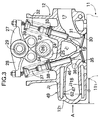
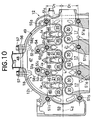
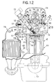
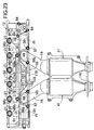
- a serial or in-line type 3-cylinder engine E includes a cylinder head 12 coupled to an upper surface of a cylinder block 11, and a head cover 13 is coupled to an upper surface of the cylinder head 12.
- Pistons 15 are slidably received in three cylinders 14 defined in the cylinder block 11, respectively, and combustion chambers 16 are defined below a lower surface of the cylinder head 12 to which upper surfaces of the pistons 15 are opposed.
- Intake ports 17 connected to the combustion chambers 16 open into a side surface of the cylinder head 12 on the intake side, and a collecting exhaust port 18 connected to the combustion chambers 16 opens into a side surface of the cylinder head 12 on the exhaust side, an exhaust pipe 19 being coupled to the opening of the collecting exhaust port 18.
- Spark plug insertion tubes 21 for attachment and detachment of spark plugs 20 are integrally formed in the cylinder head 12.
- the spark plug insertion tubes 21 are inclined, so that their upper ends are closer to the collecting exhaust port 18, with respect to a cylinder axis L 1 .
- the spark plug 20 facing the combustion chamber 16 is mounted at a lower end of each of the spark plug insertion tubes 21, and an ignition coil 22 is mounted at an upper end of each of the spark plug insertion tubes 21.
- a valve operating chamber 23 is defined in an upper portion of the cylinder head 12 and covered with the head cover 13.
- a cam shaft 26 including intake cams 24 and exhaust cams 25, and a rocker arm shaft 29, on which intake rocker arms 27 and exhaust rocker arms 28 are swingably carried.
- Intake valves 31 for opening and closing two intake valve bores 30 facing each of the combustion chambers 16 have valve stems 32 protruding into the valve operating chamber 23, so that the intake valves 31 are biased in closing directions by valve springs 33 mounted on the protruding portions of the valve stems, respectively.
- a roller 34 is mounted at one end of each of the intake rocker arms 27 to abut against the intake cam 24, and the other end abuts against an upper end of each of the valve stems 32 of the intake valves 31.
- Exhaust valves 36 for opening and closing two exhaust valve bores 35 facing each of the combustion chambers 16 have valve stems 37 protruding into the valve operating chamber 23, so that the exhaust valves 36 are biased in closing directions by valve springs 38 mounted on the protruding portions of the valve stems 37, respectively.
- a roller 39 is mounted at one end of each of the exhaust rocker arms 28 to abut against the exhaust cam 25, and the other end abuts against an upper end of each of the valve stems 37 of the exhaust valves 36.
- An injector 40 is mounted in each of the intake ports 17 and directed to the intake valve bore 30 for injecting fuel.
- each of the three intake ports 17 extending from the three combustion chambers 16 is formed into a Y-shape.
- the three intake ports 17 open independently into the side surface of the cylinder head 12 on the intake side without meeting together.
- the collecting exhaust port 18 is comprised of a total of six exhaust port sections 46 extending from the three combustion chambers 16, and an arch-shaped exhaust collection portion 47 in which the six exhaust port sections 46 are integrally collected together.
- An exhaust outlet 48 is defined at a central portion of the exhaust collecting section 47, and the exhaust pipe 19 is coupled to the exhaust outlet 48.
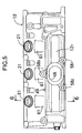
- a side wall 12 1 of the cylinder head 12 on the exhaust side surfaced by the exhaust collecting section 47 is curved into an arch shape to protrude outwards, thereby forming a protrusion 49 projecting from a side wall 11 1 of the cylinder block 11 by a distance d . Therefore, the exhaust collecting section 47 of the collecting exhaust port 18 defined within the protrusion 49 directly faces a side wall 12 1 of the protrusion 49 curved into the arch shape with no water jacket interposed therebetween.
- the cylinder head 12 can be made compact, as compared with a structure in which a water jacket is interposed between the exhaust collecting section 47 and the side wall 12 1 , because the exhaust collecting section 47 of the collecting exhaust port 18 defined within the protrusion 49 directly faces the side wall 12 1 of the protrusion 49 with no water jacket interposed therebetween, as described above. Moreover, the side wall 12 1 is formed into an arch shape and hence, the width of the lengthwise opposite ends of the cylinder head 12 is decreased. Thus, it is possible not only to provide a further compactness, but also to contribute to an enhancement in rigidity of the cylinder head 12.
- FIG.2 to 4 four bolt bores 50 are defined in the cylinder head 12 on the intake and exhaust sides, respectively, so that the cylinder head 12 is fastened to the cylinder block 11 by threadedly inserting eight cylinder head-fastening bolts 51 1 , 51 2 , 51 3 , 51 4 , 51 5 , 51 6 , 51 7 and 51 8 inserted from above in a total of eight bolt bores 50 into bolt bores 52 defined in the cylinder block 11.
- Two wall portions 53 and 54 extend within the collecting exhaust port 18, so that the central cylinder 14 and the cylinders 14 on opposite sides of the central cylinder 14 are partitioned from each other.
- Two cylinder head-fastening bolts 51 2 and 51 3 are passed through the two wall portions 53 and 54.
- Oil return passages 55 1 and 55 2 extend through tip ends of the two wall portions 53 and 54,i.e., through those portions of the two wall portions 53 and 54 which are closer to the exhaust collecting section 47 from the two cylinder head-fastening bolts 51 2 and 51 3 .
- the two wall portions 53 and 54 are curved, so that they extend in the direction of an exhaust gas flowing within the collecting exhaust port 18, i.e., they are directed to the exhaust outlet 48 located centrally. Therefore, the two oil return passages 55 1 and 55 2 are offset toward the exhaust outlet 48 with respect to the two cylinder head fastening bolts 51 2 and 51 3 adjacent the two oil return passages 55 1 and 55 2 .
- the above-described arrangement of the oil return passages 55 1 and 55 2 and the cylinder head fastening bolts 51 2 and 51 3 ensures that an exhaust gas can be allowed to flow within the collecting exhaust port 18, whereby the exhaust resistance can be reduced, while avoiding an increase in size of the cylinder head 12.
- the exhaust outlet 48 in the cylinder head 12 is provided with three boss portions 58 1 , 58 2 and 58 3 , into which three bolts 57 for fastening a mounting flange 56 of the exhaust pipe 19 are threadedly inserted, and the two oil return passages 55 1 and 55 2 are offset by a distance ⁇ in the direction of a cylinder array line L 2 with respect to the two boss portions 58 1 and 58 2 spaced apart from each other in the direction of the cylinder array line L 2 .
- the number of the exhaust pipe 19 is one and hence, the two boss portions 58 1 and 58 2 located below as viewed from above cannot be hidden below the exhaust pipe 19 and thus, it is possible to easily perform the operation of fastening the bolts 57 to the two boss portions 58 1 and 58 2 .
- the exhaust pipe 19 can be fixed at three points to enhance the mounting rigidity, while ensuring the operability of fastening the bolts 57.
- a cam driving chain chamber 59 in which a cam driving chain (not shown) is accommodated, is defined at lengthwise one end of the cylinder head 12.
- a third oil return passage 55 3 is defined in the vicinity of the cylinder head fastening bolt 51 4 located on the side opposite from the cam driving chain chamber 59.
- the three oil return passages 55 1 , 55 2 and 55 3 ensure that the valve operating chamber 23 provided in the cylinder head 12 communicates with an oil pan (not shown) through oil return passages 60 provided in the cylinder block 11.
- the two oil return passages 55 1 and 55 2 are disposed in a region surrounded by the exhaust ports 46 in adjacent ones of the cylinders 14 and the exhaust collecting section 47. Therefore, the oil return passages 55 1 and 55 2 can be defined on the exhaust side of the cylinder head 12 without interference with the collecting exhaust port 18, whereby the oil within the valve operating chamber 23 in the cylinder head 12 can reliably be returned to the oil pan. Moreover, the oil flowing through the oil return passages 55 1 and 55 2 at a low temperature can be heated by an exhaust gas flowing through the collecting exhaust port 18 and hence, the temperature of the oil can be raised without providing a special oil heater, whereby the friction resistance in each of lubricated portions can be reduced.
- the three spark plug insertion tubes 21 disposed to become inclined toward the exhaust side of the cylinder head 12 are connected with an upper surface of the protrusion 49 by reinforcing walls 61 triangular in section.
- the rigidity of the protrusion 49 can be enhanced by the reinforcing walls 61, and the vibration of the protrusion 49 during operation of the engine E can be effectively inhibited.
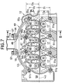
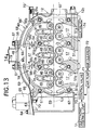
- a water jacket J 1 is defined within the cylinder head 12 to extend along the cylinder array line L 2 .
- Water jackets J 2 and J 3 covering upper and lower surfaces of the collecting exhaust port 18 are also provided in the protrusion 49 of the cylinder head 12, which is heated to a high temperature by an exhaust gas flowing through the collecting exhaust port 18.
- the upper and lower water jackets J 2 and J 3 communicate with each other through three water jackets J 4 at a portion which does not interfere with the exhaust ports 46, i.e., in the vicinity of the three spark plug insertion tubes 21.
- the exhaust side of the cylinder head 12 liable to be heated to a high temperature can be effectively cooled.
- the water jacket J 2 is interposed between ignition coils 22 serving as auxiliaries easily affected by a heat and the collecting exhaust port 18 and hence, the transfer of a heat to the ignition coils 22 can be effectively inhibited (see Fig.6).
- an outer portion of the collecting exhaust port 18 is opposed directly to the side wall 12 1 of the protrusion 49 with no water jacket interposed therebetween. Therefore, it is possible to simplify the structures of cores for forming the water jackets J 2 , J 3 and J 4 and the collecting exhaust port 18 during formation of the cylinder head 12 in a casting manner.
- the cores for forming the water jackets J 2 , J 3 and J 4 are first inserted into a mold in the direction of an arrow A and then, the core for forming the collecting exhaust port 18 is inserted into the mold in the direction of the arrow A.
- an opening 62 exists between the upper and lower water jackets J 2 and J 3 and hence, the core for forming the collecting exhaust port 18 can be inserted through the opening 62.
- the upper and lower water jackets J 2 and J 3 are connected to each other by the three water jackets J 3 , but the cores corresponding to the three water jackets J 4 are meshed alternately with those portions of the core for forming the collecting exhaust port 18 which corresponding to the six exhaust ports 46 and hence, the interference of both the cores with each other is avoided (see Fig.2).
- the cores for forming the water jackets J 2 J 3 and J 4 or the core for forming the collecting exhaust port 18 can be assembled to the mold without being divided. Therefore, when the cylinder head 12 is produced in the casting manner, the cost can be reduced.
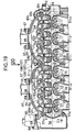
- the four cylinder head fastening bolts 51 5 , 51 6 , 51 7 and 51 8 disposed on the intake side are disposed on a straight line spaced through a distance D 1 apart from the cylinder array line L 2 intersecting the cylinder axis L 1 of the three cylinders 14.
- the distance of the two cylinder head fastening bolts 51 1 and 51 4 at opposite ends from the cylinder array line L 2 is D 1
- the distance of the cylinder head fastening bolts 51 2 and 51 3 from the cylinder array line L 2 is D 2 larger than D 1 .
- the distance between the cylinder array line L 2 and two cylinder head fastening bolts 51 6 and 51 7 , on the intake side, of the four cylinder head fastening bolts 51 2 , 51 3 , 51 6 and 51 7 disposed around an outer periphery of the central cylinder 14 closest to the exhaust collecting section 47 of the collecting exhaust port 18 is set at D 1
- the distance between the cylinder array line L 2 and the two cylinder head fastening bolts 51 2 and 51 3 on the exhaust side is set at D 2 larger than D 1 .
- the two wall portions 53 and 54 extend within the collecting exhaust port 18 to partition the central cylinder 14 and the cylinders 14 on the opposite sides from each other, and the two cylinder head fastening bolts 51 2 and 51 3 are passed through the two wall portions 53 and 54, respectively.
- the oil return passages 55 1 and 55 2 extend through base end portions of the two wall portions 53 and 54, i.e., through those portions of the two wall portions 53 and 54 which are on the side of the cylinder array line L 2 from the two cylinder head fastening bolts 51 2 and 51 3 .
- the two wall portions 53 and 54 are curved, so that they extend in the direction of an exhaust gas flowing within the collecting exhaust port 18,i.e., they are directed to the exhaust outlet 48 located centrally. Therefore, the two cylinder head fastening bolts 51 2 and 51 3 are offset toward the exhaust outlet 48 with respect to the two oil return passages 55 1 and 55 2 adjacent to the two cylinder head fastening bolts 51 2 and 51 3 .
- the protrusion 49 formed to project sideways from the cylinder head 12 has an insufficient rigidity, so that the vibration is liable to be generated during operation of the engine E.
- the protrusion 49 can be firmly fastened to the cylinder block 11, whereby the rigidity can effectively be increased, and the generation of the vibration can be inhibited.
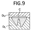
- the water jacket J 1 defined centrally in the cylinder head 12 has a heat radiating wall 12 3 extending rectilinearly along the cylinder array line L 2 therein.
- the water jacket J 1 is formed by a sand core C shown in Fig.9, when the cylinder head 12 is produced in a casting manner.
- the sand core C is formed by a mold including a lower die D L and an upper die D U .
- the heat radiating wall 12 3 is also formed by the sand core C.
- the heat radiating wall 12 3 is formed, so that the thickness is smaller at an upper portion thereof.
- the heat radiating wall 12 3 extending upwards from the lower surface of the water jacket J 1 provided in the cylinder head 12 to extend in the direction of arrangement of the combustion chambers 16 above the combustion chambers 16 is provided on the cylinder head 12 continuously in the direction of arrangement of the combustion chambers 16, the area of transfer of heat from the surroundings of the combustion chambers 16 to cooling water can be increased by the heat radiating wall 12 3 , thereby sufficiently enhancing the radiatability of heat from the surroundings of the combustion chambers 16 to the cooling water.
- the heat radiating wall 12 3 is continuous in the direction of arrangement of the combustion chambers 16, the rigidity of the entire cylinder head 12 can be increased.
- the heat radiating wall 12 3 is formed so that the thickness is smaller at an upper portion thereof, the formation of the sand core by the mold is facilitated, and the heat radiating wall 12 3 is formed integrally with the cylinder head 12 in the casting manner, leading to a remarkable effect of increasing the rigidity of the cylinder head 12 by the heat radiating wall 12 3 .
- a water outlet 12 4 of the water jacket J 1 is offset toward the intake side with respect to the heat radiating wall 12 3 .
- the heat radiating wall 12 3 can be extended to the utmost toward the water outlet 12 4 , while uniformizing the flowing of the cooling water from the opposite sides of the heat radiating wall 12 3 to the water outlet 12 4 . Therefore, the rigidity of the cylinder head 12 can be further increased, and at the same time, the heat radiatability can be enhanced by the uniformization of the flowing of the cooling water on the opposite sides of the heat radiating wall 12 3 .
- the four cylinder head fastening bolts 51 1 , 51 2 , 51 3 and 51 4 disposed on the exhaust side of the cylinder head 12 and four cylinder head fastening bolts 51 5 , 51 6 , 51 7 and 51 8 disposed on the intake side of the cylinder head 12 are all disposed at locations spaced through the distance D 1 apart from the cylinder array line L 2 .
- Two exhaust collecting section fastening bolts 51 9 and 51 10 are disposed in two wall portions 53 and 54 partitioning the central cylinder 14 and the cylinders 14 on the opposite sides from each other, so that the bolts 51 9 and 51 10 are located outside oil return passages 55 1 and 55 2 (at locations farther from the cylinder array line L 2 ).
- the two exhaust collecting section fastening bolts 51 9 and 51 10 on the side of the exhaust collecting section 47 which are additionally provided in this embodiment, have a diameter smaller than those of the two cylinder head fastening bolts 51 2 and 51 3 on the side of the combustion chamber 16. This can contribute to the avoidance of an increase in size of the cylinder head 12 and to a reduction in exhaust resistance.
- the two exhaust collecting section fastening bolts 51 9 and 51 10 are additionally provided on the exhaust side of the cylinder head 12 to couple the exhaust collecting section 47 to the cylinder block 11. Therefore, it is possible not only to increase the rigidity of the protrusion 49 to effectively inhibit the generation of the vibration, but also to ensure the sealability of the coupled surfaces of the cylinder head 12 and the cylinder block 11. Moreover, since each of the two oil return passages 55 1 and 55 2 is interposed between the two bolts 51 2 and 51 9 as well as 51 3 and 51 10 , respectively, the sealability of the oil return passages 55 1 and 55 2 is also enhanced.
- the two wall portions 53 and 54 are curved toward the central exhaust outlet 48 to extend along the direction of an exhaust gas flowing within the collecting exhaust port 18, and the two cylinder head fastening bolts 51 2 and 51 3 , the two oil return passages 55 1 and 55 2 and the two exhaust collecting section fastening bolts 51 9 and 51 10 are disposed in the wall portions 53 and 54 to extend from a location closer to the cylinder array line L 2 or a central cylinder axis L 1 to a location farther from the cylinder array line L 2 or the central cylinder axis L 1 . Therefore, it is possible to ensure that the exhaust gas flows smoothly within the collecting exhaust port 18, whereby the exhaust resistance can be reduced, while avoiding an increase in size of the cylinder head 12.
- the four cylinder head fastening bolts 51 1 , 51 2 , 51 3 and 51 4 disposed on the exhaust side of the cylinder head 12 and four cylinder head fastening bolts 51 5 , 51 6 , 51 7 and 51 8 disposed on the intake side of the cylinder head 12 are all disposed at locations spaced through the distance D 1 apart from the cylinder array line L 2 .
- the protrusion 49 and a protrusion projecting from the side wall 11 1 of the cylinder block 11 are coupled to each other by two exhaust collecting section fastening bolts 51 9 and 51 10 each having a smaller diameter.
- each of the two exhaust collecting section fastening bolts 51 9 and 51 10 on the side of the exhaust collecting section 47 has a diameter smaller than those of the two cylinder head fastening bolts 51 2 and 51 3 on the side of the combustion chamber 16 and hence, an increase in size of the cylinder head 12 can be prevented.
- the exhaust pipe 19 coupled to the exhaust outlet 48 of the collecting exhaust port 18 defined in the protrusion 49 of the cylinder head 12 is bent downwards at 90°, and a substantially cylindrical exhaust emission control catalyst 41 is mounted in the exhaust pipe 19.
- a portion of the exhaust emission control catalyst 41 disposed vertically to extend along a side surface of the cylinder block 11 extends below the protrusion 49 of the cylinder head 12.
- such portion of the exhaust emission control catalyst 41 overlaps with the protrusion 49 below the latter, as viewed in the direction of the cylinder axis L 1 .
- the exhaust emission control catalyst 41 is accommodated in a recess 43 which is defined by a lower surface of the protrusion 49 of the cylinder head 12, the side surface of the cylinder block 11 and an upper surface of a crankcase bulge 11 2 and hence, the entire engine E including the exhaust emission control catalyst 41 can be made compact.
- the exhaust emission control catalyst 41 is disposed at a location extremely near the exhaust outlet 48 of the collecting exhaust port 18 and hence, an exhaust gas having a high temperature can be supplied to the exhaust emission control catalyst 41 to raise the temperature of the exhaust emission control catalyst 41, thereby promoting the activation of the exhaust emission control catalyst 41.
- a first exhaust secondary air passage 66 and a second exhaust secondary air passage 67 are defined in the cylinder head 12.
- Two ribs 68 and 69 are formed in the arch-shaped side wall 12 1 of the protrusion 49 of the cylinder head 12 to extend lengthwise of the cylinder head 12 with the exhaust outlet 48 interposed therebetween, and the first exhaust secondary air passage 66 is defined within one of the ribs 69.
- the first exhaust secondary air passage 66 is defined to extend along the side wall 12 1 of the arch-shaped protrusion 49 and hence, an increase in size of the cylinder head 12 and an increase in vibration can be inhibited.
- An outlet 66 (an air introduction opening for introducing exhaust secondary air into an exhaust system) is provided at one end of the first exhaust secondary air passage 66, and opens in the vicinity of the exhaust outlet 48 of the exhaust collecting section 47, and the other end of the first exhaust secondary air passage 66 opens into an end surface of the cylinder head 12 and is occluded by a plug 70.
- One end of the second exhaust secondary air passage 67 defined along the end surface of the cylinder head 12 opens in the vicinity of the other end of the first exhaust secondary air passage 66, and the other end of the passage 67 opens into the side wall 12 2 of the cylinder head 12 on the intake side.
- Exhaust secondary air introduced from an air cleaner 72 by an air pump 71 is supplied via a control valve 73 to the second exhaust secondary air passage 67 which opens into the side wall 12 2 of the cylinder head 12 on the intake side.
- the air pump 71 and the control valve 73 are connected to and controlled by an electronic control unit U.
- the exhaust emission control catalyst is inactive, immediately after operation of the engine E, the operations of the air pump 71 and the control valve 73 are controlled by a command from the electronic control unit U, and the exhaust secondary air supplied to the second exhaust secondary air passage 67 is supplied via the first exhaust secondary air passage 66 to the exhaust collecting section 47 of the collecting exhaust port 18.
- harmful components such as HC and CO in the exhaust gas can be converted into harmless components by reburning, and moreover, the exhaust emission control catalyst can be activated early, thereby providing a satisfactory exhaust gas purifying effect.
- the outlet 66 1 of the first exhaust secondary air passage 66 opens into the exhaust collecting section 47 which is difficult to be influenced by the inertia and pulsation of the exhaust gas, because the plurality of exhaust ports 46 are collected therein. Therefore, the influence of the inertia and pulsation of the exhaust gas can be eliminated, and the exhaust secondary air can be supplied stably without complication of the structures of the passages for supplying the exhaust secondary air.
- the first and second exhaust secondary air passages 66 and 67 are integrally defined in the cylinder head 12, the space and the number of parts can be reduced, as compared with the case where exhaust secondary air passages are defined by separate members outside the cylinder head 12.
- the rigidity of the protrusion 49 can be increased by the ribs 68 and 69, whereby the vibration can be reduced.
- the two ribs 68 and 69 connect the end of the cylinder head 12 to the boss portions 58 1 and 58 2 for mounting the exhaust pipe 19, which contributes to the increase in rigidity of mounting of the exhaust pipe 19.
- one of the ribs 69 is connected to a tensioner mounting seat 63 for supporting a chain tensioner 65, whereby the rigidity of mounting of the exhaust pipe 19 and the rigidity of mounting of the chain tensioner 65 are effectively increased.
- EGR passages are defined by utilizing the protrusion 49 of the cylinder head 12.
- An EGR gas supply system includes a first EGR gas passage 66' and a second EGR gas passage 67'.
- the first EGR gas passage 66' is defined within the other rib 68 of the protrusion 49 of the cylinder head 12.
- An inlet 66 1 ' at one end of the first EGR gas passage 66' opens in the vicinity of the exhaust outlet 48 of the exhaust collecting section 47, and the other end of the first EGR gas passage 66' opens into the end surface of the cylinder head 12 and is occluded by a plug 70'.
- One end of the second EGR gas passage 67' defined along the end surface of the cylinder head 12 opens in the vicinity of the other end of the first EGR gas passage 66', and the other end of the passage 67' opens into the side wall 12 2 of the cylinder head 12 on the intake side.
- the second EGR gas passage 67' opening into the side wall 12 2 of the cylinder head 12 on the intake side is connected to the three intake ports 17 through an EGR valve 74 for controlling the flow rate of an EGR gas.
- an exhaust gas removed from the collecting exhaust port 18 is recirculated to the intake system through the first and second EGR gas passages 66' and 67' and the EGR valve 74, whereby the generation of NOx by combustion can be inhibited, and NOx in the exhaust gas can be reduced.
- the inlet 66 1 ' of the first EGR gas passage 66' opens into the exhaust collecting section 47 which is difficult to be influenced by the inertia and pulsation of the exhaust gas, because the plurality of exhaust ports 46 are collected therein. Therefore, the influence of the inertia and pulsation of the exhaust gas can be eliminated, and the EGR gas can be stably supplied.
- the first and second EGR gas passages 66' and 67' are integrally defined in the cylinder head 12, the space and the number of parts can be reduced, as compared with the case where EGR gas passages are defined by separate members outside the cylinder head 12.
- an oxygen concentration sensor 82 for detecting a concentration of oxygen in an exhaust gas is mounted in the vicinity of an exhaust outlet 48 defined at an outer end of the protrusion 49 of the cylinder head 12.
- the oxygen concentration sensor 82 includes a body portion 82 1 fixed in the vicinity of the exhaust outlet 48 of the protrusion 49, a detecting portion 82 2 provided at a tip end of the body portion 82 1 to face the exhaust collecting section 47, and a harness 82 3 extending from a rear end of the body portion 82 1 .
- the body portion 82 1 is disposed parallel to the cylinder array line L 2 , so that it is opposed to the side wall 12 1 of the protrusion 49.
- the detecting portion 82 2 of the oxygen concentration sensor 82 faces the exhaust collecting section 47 where exhaust gasses from the three combustion chambers 16 are collected. Therefore, a concentration of oxygen in an exhaust gas in the entire engine E can be detected by the single oxygen concentration sensor 82, and the number of the oxygen concentration sensors 82 can be maintained to the minimum. Moreover, by provision of the oxygen concentration sensor 82 in the exhaust collecting section 47 of the cylinder head 12. the oxygen concentration sensor 82 can be early raised in temperature for activation by heat of the exhaust gas having a high temperature immediately after leaving the combustion chambers 16.
- the protrusion 49 is formed into the arch shape, dead spaces are defined on opposite sides of the protrusion 49 in the direction of the cylinder array line L 2 .
- the oxygen concentration sensor 82 is mounted in the vicinity of the outer end of the arch-shaped protrusion 49 with the body portion 82 1 provided in an opposed relation to and along the side wall 12 1 of the protrusion 49, the oxygen concentration sensor 82 can be disposed compactly by effectively utilizing one of the dead spaces.
- the body portion 82 1 of the oxygen concentration sensor 82 is gradually more and more spaced apart from the side wall 12 1 of the protrusion 49. Therefore, the distance of the harness 82 3 extending from the body portion 82 1 from the protrusion 49 can be ensured sufficiently, thereby alleviating the thermal influence received by the harness 82 3 .
- the oxygen concentration sensor 82 is disposed on the opposite side from the cam driving chain chamber 59 where the other member such as the chain tensioner 65 is mounted. Therefore, it is possible to prevent the interference of the oxygen concentration sensor 82 with the other member such as the chain tensioner 65 during the attachment and removal of the oxygen concentration sensor 82, leading to an enhanced workability, and moreover, the oxygen concentration sensor 82 and the other member can be disposed compactly in a distributed manner on opposite sides in the direction of the cylinder array line L 2 .
- two vibration absorbing means D are mounted in the side wall 11 1 of the cylinder block 11 on the exhaust side.
- a through-bore 11 3 defined in the side wall 11 1 of the cylinder block 11 to mount each of the vibration absorbing means D has an inner end which opens into a water jacket J 5 defined in the cylinder block 11, and an outer end which opens into an outer surface of the side wall 11 1 of the cylinder block 11.
- a housing 92 having an external threaded portion formed in its outer peripheral surface is screwed into internal threaded portion formed in an inner peripheral surface of the through-bore 11 3 from the outer surface of the side wall 11 1 , and is fixed to the inner peripheral surface of the through-bore 11 3 with a seal member 93 interposed between the housing 92 and the cylinder block 11.
- An elastic membrane 94 is affixed to an opening at a tip end of the housing 92 of which inside is hollow, and a closed space 95 is defined between the elastic membrane 94 and the housing 92. In a state in which the housing 92 has been mounted in the through-bore 11 3 , the elastic membrane 94 faces the water jacket J 5 .
- the elastic membrane 94 is formed from a rubber or a synthetic resin reinforced with a fabric, a synthetic fiber or a glass fiber and is fixed in the opening in the housing 92, for example, by baking. In a state in which the vibration absorbing means D has been mounted in the through-bore 11 3 in the side wall 11 1 of the cylinder block 11, the elastic membrane 94 is disposed substantially flush with the wall surface of the water jacket J 5 so as not to protrude in the water jacket J 5 .
- the two vibration absorbing means D are disposed at locations on left and right sides of and deviated from the exhaust pipe 19, as the side wall 11 1 of the cylinder block 11 on the exhaust side is viewed from the front.
- the two vibration absorbing means D are disposed out of a region of such projection.
- the above-described arrangement ensures that the heat of the exhaust pipe 19 heated to a high temperature is difficult to be transferred to the vibration absorbing means D, whereby the degradation in durability of the elastic membrane 94 easily affected by the heat can be prevented.
- the heat transferred to the vibration absorbing means D can be further diminished by the disposition of a heat insulting plate 96 between the exhaust pipe 19 and the cylinder block 11.
- the vibration absorbing means D are disposed at locations close to top dead centers of the pistons 15, namely, at locations close to the cylinder head 12 in order to enhance the noise preventing effect. If the vibration absorbing means D are disposed in proximity to the cylinder head 12, they are liable to interfere with the exhaust pipe 19. According to the present embodiment, however, the disposition of the vibration absorbing means D out of the region of projection of the exhaust pipe 19 ensures that even if the exhaust pipe 19 is disposed in proximity to the cylinder block 11, the exhaust pipe 19 cannot interfere with the vibration absorbing means D. Therefore, the exhaust pipe 19 can be disposed in sufficient proximity to the cylinder block 11, whereby the engine E can be made compact.
- the engine E in the ninth embodiment is a serial or in-line type 6-cylinder engine, wherein each of the six intake ports 17 extending from the six combustion chambers 16 is formed into a Y-shape.
- the six intake ports 17 open independently into a side surface of the cylinder head 12 on the intake side without being collected together.
- each of first and second collecting exhaust ports 18a and 18b is comprised of a total of six exhaust ports 46 extending from the three combustion chambers 16, respectively, and an arch-shaped first/second exhaust collecting section 47a, 47b where the six exhaust ports 46 are integrally collected together.
- Exhaust outlets 48, to which the exhaust pipes 19 are coupled, are defined in central portions of the first and second exhaust collecting section 47a and 47b.
- the first collecting exhaust port 18a permits exhaust gases from the combustion chambers 16 in the three #4, #5 and #6 cylinders on one end side of a cylinder array line L 2 to be collected in the first exhaust collecting section 47a
- the second collecting exhaust port 18b permits exhaust gases from the combustion chambers 16 in the three #1, #2 and #3 cylinders on the other end side of the cylinder array line L 2 to be collected in the second exhaust collecting section 47b.
- the first and second collecting exhaust ports 18a and 18b have substantially the same structure.
- cores for forming the collecting exhaust ports during the casting production of the cylinder head 12 can be reduced in size, and moreover, one type of the cores can be used to contribute to a reduction in cost.
- the order of ignition of the #1, #2, #3, #4, #5 and #6 cylinders is #1 ⁇ #5 ⁇ #3 ⁇ #6 ⁇ #2 ⁇ #4.
- the order of ignition of the three #1, #2 and #3 cylinders corresponding to the first collecting exhaust port 18a is not continuous, and the order of ignition of the three #4, #5 and #6 cylinders corresponding to the second collecting exhaust port 18b is not continuous either. Therefore, an exhaust interference among the three #1, #2 and #3 cylinders corresponding to the first collecting exhaust port 18a is not generated, and an exhaust interference among the three #4, #5 and #6 cylinders corresponding to the second collecting exhaust port 18b is not generated either.
- first and second exhaust collecting sections 47a and 47b of the first and second collecting exhaust ports 18a and 18b defined in the first and second protrusions 49a and 49b directly face the side walls 12 1 of the arch-shaped first and second protrusions 49a and 49b with no water jacket interposed therebetween.
- the cylinder head 12 can be made compact, and it is easy to form the cylinder head 12, as compared with the case where a water jacket is interposed between the first and second exhaust collecting sections 47a and 47b and the side walls 12 1 . Moreover, since the side wall 12 1 is formed into the arch shape, the width of lengthwise opposite ends of the cylinder head 12 is decreased.
- a recess 101 (see Fig.19) is defined between the first and second protrusions 49a and 49b and hence, it is possible to provide a reduction in size of the engine E by effectively utilizing a space in the recess 101.
- Seven bolts bores 50 are defined in the cylinder head 12 on the intake and exhaust sides, respectively.
- the cylinder head 12 is fastened to the cylinder block 11 by screwing fourteen cylinder head fastening bolts 51 1 , 51 2 , 51 3 , 51 4 , 51 5 , 51 6 , 51 7 , 51 8 , 51 9 , 51 10 , 51 11 , 51 12 , 51 13 and 51 14 inserted from above in a total of fourteen bolt bores 50 into the bolt bores 52 defined in the cylinder block 11.
- the two wall portions 53 and 54 extend within the first collecting exhaust port 18a to partition the three cylinders 14 corresponding to the first collecting exhaust port 18a from one another.
- the two cylinder head fastening bolts 51 2 and 51 3 are passed through the two wall portions 53 and 54.
- the oil return passages 55 1 and 55 2 as oil passages are provided to extend through tip end areas of the two wall portions 53 and 54,i.e., areas of the two wall portions 53 and 54 on the side of the first exhaust collecting section 47a from the two cylinder head fastening bolts 51 2 and 51 3 , respectively.
- the two wall portions 53 and 54 extend within the second collecting exhaust port 18b to partition the three cylinders 14 corresponding to the second collecting exhaust port 18b from one another.
- the two cylinder head fastening bolts 51 5 and 51 6 are passed through the two wall portions 53 and 54, respectively.
- the oil return passages 55 3 and 55 4 as oil passages are provided to extend through tip end areas of the two wall portions 53 and 54, i.e., areas of the two wall portions 53 and 54 on the side of the second exhaust collecting section 47b from the two cylinder head fastening bolts 51 5 and 51 6 , respectively.
- the two wall portions 53 and 54 are curved, so that they extend in the direction of flowing of an exhaust gas within the first collecting exhaust port 18a, i.e., so that they are directed to the exhaust outlet 48 located centrally. Therefore, the two oil return passages 55 1 and 55 2 are offset toward the exhaust outlet 48 with respect to the two adjacent cylinder head fastening bolts 51 2 and 51 3 .
- the above-described arrangement of the oil return passages 55 1 and 55 2 and the cylinder head fastening bolts 51 2 and 51 3 ensures that an exhaust gas can flow smoothly within the first collecting exhaust port 18a, whereby the exhaust resistance can be reduced, while avoiding an increase in size of the cylinder head 12.
- the second collecting exhaust port 18b has the same structure as the above-described structure of the first collecting exhaust port 18a.
- the recess 101 is defined between the first and second protrusions 49a and 49b formed into the arch shape and has such a shape that it extends along the first and second collecting exhaust ports 18a and 18b.
- the first and second protrusions 49a and 49b are connected to each other by a pair of upper and lower connecting walls 102 and 103 which are disposed above and below the recess 101.
- a fifteenth cylinder head fastening bolt 51 15 for fastening the cylinder head 12 to the cylinder block 11 is supported at its head on an upper surface of the lower connecting wall 103.
- the above-described arrangement ensures that a portion fastening between the cylinder head 12 and cylinder block 11 by the fifteenth cylinder head fastening bolt 51 15 can be made compact and moreover, the cross section of a flow path in a communication passage 107 (which will be described hereinafter) in the upper connecting wall 102 can be increased.
- a sixth oil return passage 55 6 as an oil passage is defined between the two cylinder head fastening bolts 51 4 and 51 15 and communicates with the oil pan through an oil return passage 109 defined in the cylinder block 11.
- the oil return passage 55 6 is defined at a location between the first and second protrusions 49a and 49b. Therefore, an increase in size of the cylinder head 12 is avoided, and moreover, a portion defining the oil return passage 55 6 can be allowed to function as a wall connecting the first and second protrusions 49a and 49b, thereby increasing the rigidity of the cylinder head 12 to alleviate the vibration of the first and second protrusions 49a and 49b.
- the vicinity of the oil return passage 55 6 can be heated by the heat from the first and second collecting exhaust ports 18a and 18b in the first and second protrusions 49a and 49b without providing a special oil heater, thereby reducing the viscosity of an oil to decrease the friction resistance of each of various sliding portions.
- the first and second protrusions 49a and 49b are connected to each other by the connecting walls 102 and 103, as described above, the first and second protrusions 49a and 49b can be reinforced by each other, whereby the rigidity thereof can be increased, and the generation of the vibration can be inhibited. Additionally, the thermal strain of the first and second protrusions 49a and 49b having the first and second collecting exhaust ports 18a and 18b which are defined therein and through which a high-temperature exhaust gas flows can be maintained to the minimum.
- the rigidity of the first and second protrusions 49a and 49b can be increased, thereby further effectively preventing the generation of the vibration, and moreover, enhancing the sealability between the cylinder head 12 and the cylinder block 11.
- Communication passages 107 and 108 through which cooling water flows, are defined in the upper and lower connecting walls 102 and 103, respectively.
- the upper water jackets J 2 in the first and second protrusions 49a and 49b communicate with each other through the communication passage 107 in the upper connecting wall 102
- the lower water jackets J 3 in the first and second protrusions 49a and 49b communicate with each other through the communication passage 108 in the lower connecting wall 103.
- the basic structure of the engine E in the tenth embodiment is identical to that of a serial or in-line type 6-cylinder engine similar to that in the ninth embodiment.
- Two exhaust pipes 19 coupled to exhaust outlets 48 of the first and second collecting exhaust ports 18a and 18b in the first and second protrusions 49a and 49b are integrally connected at their upstream portions to each other by the common mounting flange 56.
- the mounting flange 56 includes boss portions 56 1 , 56 2 and 56 3 at its opposite ends, respectively.
- the two upper opposed boss portions 56 3 , 56 3 are connected to each other by a bar-shaped connecting portion 114, and two lower opposed boss portions 56 1 , 56 1 are connected to each other by a bar-shaped connecting portion 115. Therefore, the mounting flange 56 for two exhaust pipes 19 is coupled to the cylinder head 12 by a total of six bolts 57.
- the two opposed boss portions 56 3 , 56 3 of the mounting flange 56 for the exhaust pipes 19 are fastened by the bolts 57 to the reinforcing walls 61 which connect the spark plug insertion tubes 21 with the upper surfaces of the first and second protrusions 49a and 49b. Therefore, the rigidity of support of the exhaust pipes 19 can be remarkably increased to alleviate the vibration.
- Two exhaust emission control catalysts 41 mounted at lower portions of the two exhaust pipes 19, respectively, are integrally coupled to each other by a connecting flange 116 which is mounted at lower ends of the exhaust emission control catalysts 41 to couple further downstream exhaust pipes (not shown) integrally coupled each other at opposed portions of the exhaust emission control catalysts 41.
- the distance from the combustion chambers 16 to the exhaust emission control catalysts 41 can be shortened to prevent the drop of the temperature of an exhaust gas, and the exhaust emission control catalysts 41 can be promptly activated by the heat of the exhaust gas to enhance the exhaust emission control performance.
- both of the exhaust pipes 19 are integrally connected to each other at their lower portions by the exhaust emission control catalysts 41 and at their upper portions by the mounting flange 56 and hence, the exhaust pipes 19 the exhaust emission control catalysts 41 and the mounting flange 56 reinforce one another, whereby the vibration can be alleviated.
- the mounting flange 56 is fastened at its opposite ends to the exhaust outlets 48 of the first and second collecting exhaust ports 18a and 18b to have a span long enough in the direction of the cylinder array line L 2 and hence, the rigidity of supporting of the exhaust pipes 19 is increased, and the vibration alleviating effect is further enhanced.
- reinforcing members such as stays for supporting the exhaust pipes 19 and the exhaust emission control catalysts 41 are not required for alleviating the vibration, which can contribute to a reduction in number of parts and the compactness of the engine E.
- in-line type 3-cylinder engine E and the in-line type 6-cylinder engine E have been illustrated in the embodiments, but the present invention is also applicable to banks of other in-line type engines having a different number of cylinders and V-type engines.
- oil return passages 55 1 to 55 6 have been illustrated as the oil passages in the embodiments, but the oil passages used in the present invention include an oil supply passage for supplying an oil from the cylinder block 11 to the valve operating chamber 23 within the cylinder head 12, and a blow-by gas passage which permits the valve operating chamber 23 within the cylinder head 12 to communicate with the crankcase to perform the ventilation of a blow-by gas.
- the exhaust emission control catalyst 41 has a circular cross section in the embodiments, but the cross section of the exhaust emission control catalyst 41 need not be necessarily circular. If the cross section of the exhaust emission control catalyst 41 is of an elliptic shape having a longer axis in the direction toward the cylinder axis L 1 , or of such a non-circular shape that it is bulged in the direction toward the cylinder axis L 1 , the dead space below the protrusion 49 can be effectively utilized.
- the structure of the vibration absorbing means D is not limited to that in each of the embodiments, and other various structures can be employed.
- the pluralities of protrusions, exhaust collecting sections and collecting exhaust ports are provided, and the number of each of them is not necessarily limited to two and may be three or more.
- the number of the connecting walls 102 and 103 is not necessarily limited to two and may be one or three or more.
- the water jackets J 2 and J 3 may be defined in only either one of the upper and lower surfaces of the first and second exhaust collecting sections 47a and 47b, in place of being defined in both of the upper and lower surfaces.
Landscapes
- Engineering & Computer Science (AREA)
- Chemical & Material Sciences (AREA)
- Combustion & Propulsion (AREA)
- Mechanical Engineering (AREA)
- General Engineering & Computer Science (AREA)
- Cylinder Crankcases Of Internal Combustion Engines (AREA)
- Lubrication Of Internal Combustion Engines (AREA)
Priority Applications (1)
| Application Number | Priority Date | Filing Date | Title |
|---|---|---|---|
| EP06018306.8A EP1722090B1 (de) | 1998-12-01 | 1999-05-19 | Mehrzylinderkopf |
Applications Claiming Priority (4)
| Application Number | Priority Date | Filing Date | Title |
|---|---|---|---|
| JP34122898 | 1998-12-01 | ||
| JP34122898A JP3569636B2 (ja) | 1998-12-01 | 1998-12-01 | 多気筒エンジンのシリンダヘッド構造 |
| JP34122798 | 1998-12-01 | ||
| JP34122798A JP3605521B2 (ja) | 1998-12-01 | 1998-12-01 | 多気筒エンジンのシリンダヘッド構造 |
Related Child Applications (1)
| Application Number | Title | Priority Date | Filing Date |
|---|---|---|---|
| EP06018306.8A Division EP1722090B1 (de) | 1998-12-01 | 1999-05-19 | Mehrzylinderkopf |
Publications (3)
| Publication Number | Publication Date |
|---|---|
| EP1006272A2 true EP1006272A2 (de) | 2000-06-07 |
| EP1006272A3 EP1006272A3 (de) | 2003-01-29 |
| EP1006272B1 EP1006272B1 (de) | 2007-04-11 |
Family
ID=26576922
Family Applications (2)
| Application Number | Title | Priority Date | Filing Date |
|---|---|---|---|
| EP06018306.8A Expired - Lifetime EP1722090B1 (de) | 1998-12-01 | 1999-05-19 | Mehrzylinderkopf |
| EP99303906A Expired - Lifetime EP1006272B1 (de) | 1998-12-01 | 1999-05-19 | Mehrzylinderkopf |
Family Applications Before (1)
| Application Number | Title | Priority Date | Filing Date |
|---|---|---|---|
| EP06018306.8A Expired - Lifetime EP1722090B1 (de) | 1998-12-01 | 1999-05-19 | Mehrzylinderkopf |
Country Status (7)
| Country | Link |
|---|---|
| US (2) | US6513506B1 (de) |
| EP (2) | EP1722090B1 (de) |
| CN (1) | CN1153897C (de) |
| CA (1) | CA2272416C (de) |
| DE (1) | DE69935776T2 (de) |
| MY (1) | MY121430A (de) |
| TW (1) | TW399124B (de) |
Cited By (17)
| Publication number | Priority date | Publication date | Assignee | Title |
|---|---|---|---|---|
| EP1195504A3 (de) * | 2000-10-03 | 2003-04-16 | Mazda Motor Corporation | Motorblockstruktur für eine Brennkraftmaschine |
| US7051685B2 (en) | 2003-10-27 | 2006-05-30 | General Motors Corporation | Cylinder head with integrated exhaust manifold |
| EP1840351A3 (de) * | 2006-03-29 | 2007-12-19 | HONDA MOTOR CO., Ltd. | Wassergekühlter Verbrennungsmotor |
| US7367294B2 (en) | 2006-03-14 | 2008-05-06 | Gm Global Technology Operations, Inc. | Cylinder head with integral tuned exhaust manifold |
| EP2077386A1 (de) * | 2008-01-07 | 2009-07-08 | Ford Global Technologies, LLC | Zylinderkopf mit im Zylinderkopf integriertem Abgaskrümmer |
| EP2077385A1 (de) * | 2008-01-07 | 2009-07-08 | Ford Global Technologies, LLC | Zylinderkopf für eine Brennkraftmaschine mit angrenzendem Bauteil |
| EP2077388A3 (de) * | 2008-01-07 | 2009-10-28 | Ford Global Technologies, LLC | Kombination mit Zylinderkopf und Zylinderblock und Verwendung einer derartigen Kombination |
| EP2143898A1 (de) * | 2008-07-09 | 2010-01-13 | Ford Global Technologies, LLC | Anordnung mit Zylinderkopf und Zylinderblock |
| EP2143922A1 (de) * | 2008-07-11 | 2010-01-13 | Ford Global Technologies, LLC | Zylinderkopf mit Abgaskrümmer und Turbolader |
| EP2206896A1 (de) * | 2009-01-09 | 2010-07-14 | Peugeot Citroen Automobiles SA | Kühlungsvorrichtung eines im Zylinderkopf integrierten Abgaskrümmers |
| DE10141534B4 (de) * | 2000-08-25 | 2011-07-07 | Honda Giken Kogyo K.K. | Zylinderkopf einer Mehrzylinder-Brennkraftmaschine mit innen liegenden Auslasskanälen |
| EP2077387B1 (de) * | 2008-01-07 | 2011-07-27 | Ford Global Technologies, LLC | Verfahren zur Kühlung eines rückzuführenden Abgasstroms einer Brennkraftmaschine |
| EP1828604A4 (de) * | 2004-11-29 | 2012-11-07 | Haldex Brake Corp | Verdichter mit verstärktem kolbenkanal |
| EP2113648A4 (de) * | 2007-02-07 | 2013-01-09 | Toyota Motor Co Ltd | Zylinderkopf für einen verbrennungsmotor |
| EP2369161A3 (de) * | 2010-03-26 | 2015-05-20 | Bayerische Motoren Werke Aktiengesellschaft | Zylinderkopf und Abgaskrümmer sowie Abgasabströmanordnung |
| DE102010034953B4 (de) * | 2009-09-21 | 2016-06-16 | GM Global Technology Operations LLC (n. d. Ges. d. Staates Delaware) | Abgasbehandlungssystem für einen Verbrennungsmotor |
| FR3049981A1 (fr) * | 2016-04-11 | 2017-10-13 | Peugeot Citroen Automobiles Sa | Moteur a combustion interne comportant une conduite de redirection des gaz d'echappement integree a la culasse |
Families Citing this family (82)
| Publication number | Priority date | Publication date | Assignee | Title |
|---|---|---|---|---|
| SE521262C2 (sv) * | 2000-06-28 | 2003-10-14 | Volvo Lastvagnar Ab | Förbränningsmotor med återcirkulation av avgaser |
| WO2003071116A1 (en) * | 2002-02-20 | 2003-08-28 | Yamaha Hatsudoki Kabushiki Kaisha | Engine fastening structure |
| JP4133454B2 (ja) * | 2003-03-05 | 2008-08-13 | 本田技研工業株式会社 | 内燃機関のシリンダヘッド |
| AT413861B (de) * | 2003-11-03 | 2006-06-15 | Avl List Gmbh | Auslasskanalanordnung für eine brennkraftmaschine |
| JP4257528B2 (ja) * | 2004-07-05 | 2009-04-22 | 三菱自動車工業株式会社 | 多気筒内燃機関 |
| US8220264B2 (en) * | 2005-09-13 | 2012-07-17 | GM Global Technology Operations LLC | Integrated inboard exhaust manifolds for V-type engines |
| US7552586B1 (en) * | 2005-12-12 | 2009-06-30 | Brunswick Corporation | Marine exhaust system with a downstream oxygen sensor located away from a water reversion liquid trajectory path |
| US20090126674A1 (en) * | 2005-12-14 | 2009-05-21 | Yamaha Hatsudoki Kabushiki Kaisha | Engine and vehicle |
| JP2007309136A (ja) * | 2006-05-16 | 2007-11-29 | Toyota Motor Corp | 内燃機関 |
| US7712802B2 (en) * | 2006-06-12 | 2010-05-11 | Alcon, Inc. | Cassette clamping mechanism |
| JP4525646B2 (ja) * | 2006-08-09 | 2010-08-18 | トヨタ自動車株式会社 | 内燃機関 |
| JP4337851B2 (ja) * | 2006-08-28 | 2009-09-30 | トヨタ自動車株式会社 | シリンダヘッドの冷却水通路構造 |
| JP4306718B2 (ja) * | 2006-11-10 | 2009-08-05 | トヨタ自動車株式会社 | シリンダヘッド |
| JP4748081B2 (ja) * | 2007-02-23 | 2011-08-17 | トヨタ自動車株式会社 | 内燃機関の排気装置 |
| EP2003320B1 (de) * | 2007-06-13 | 2017-10-11 | Ford Global Technologies, LLC | Zylinderkopf für eine Brennkraftmaschine |
| DE102007046657A1 (de) * | 2007-09-28 | 2009-04-09 | Audi Ag | Brennkraftmaschine |
| KR100916773B1 (ko) * | 2007-12-12 | 2009-09-14 | 현대자동차주식회사 | 포트-배기매니폴드 일체형 실리더헤드 |
| DE102008035957B4 (de) | 2008-07-31 | 2014-08-07 | Ford Global Technologies, Llc | Zylinderkopf für eine Brennkraftmaschine |
| WO2010015654A1 (de) * | 2008-08-08 | 2010-02-11 | Ford Global Technologies, Llc | Motoranordnung mit integriertem abgaskrümmer |
| US7926473B2 (en) * | 2008-09-12 | 2011-04-19 | Ford Global Technologies | Air supply system for an internal combustion engine |
| US8146359B2 (en) * | 2008-09-12 | 2012-04-03 | Ford Global Technologies, Llc | Dual inlet turbocharger system for internal combustion engine |
| US8056525B2 (en) * | 2008-09-12 | 2011-11-15 | Ford Global Technologies | Induction system for internal combustion engine |
| US7950363B2 (en) * | 2008-09-12 | 2011-05-31 | Ford Global Technologies | Air inlet system for internal combustion engine |
| US7743756B2 (en) * | 2008-09-12 | 2010-06-29 | Ford Global Technologies | Air inlet system for an internal combustion engine |
| FR2936014B1 (fr) * | 2008-09-18 | 2010-09-17 | Peugeot Citroen Automobiles Sa | Culasse de moteur a combustion integrant un collecteur d'echappement. |
| EP2172635B1 (de) | 2008-10-02 | 2018-12-12 | Ford Global Technologies, LLC | Zylinderkopf für eine Brennkraftmaschine mit zwei integrierten Abgaskrümmern und Verfahren zum Betreiben einer Brennkraftmaschine mit einem derartigen Zylinderkopf |
| KR20100064889A (ko) * | 2008-12-05 | 2010-06-15 | 현대자동차주식회사 | 실린더헤드 일체형 배기순환장치를 갖는 egr시스템 |
| US8146544B2 (en) * | 2009-03-05 | 2012-04-03 | GM Global Technology Operations LLC | Engine cylinder head cooling features and method of forming |
| DE102009001542A1 (de) | 2009-03-13 | 2010-10-07 | Ford Global Technologies, LLC, Dearborn | Zylinderkopf für einen Saugmotor und Verwendung eines derartigen Zylinderkopfes |
| JP5548478B2 (ja) * | 2009-03-31 | 2014-07-16 | 株式会社クボタ | 火花点火式エンジン |
| AT506473B1 (de) | 2009-04-23 | 2010-12-15 | Avl List Gmbh | Zylinderkopf einer brennkraftmaschine |
| DE102009028632A1 (de) | 2009-08-19 | 2011-03-03 | Ford Global Technologies, LLC, Dearborn | Flüssigkeitsgekühlte Brennkraftmaschine mit flüssigkeitsgekühlter Turbine |
| DE102009029289B4 (de) | 2009-09-09 | 2013-08-08 | Ford Global Technologies, Llc | Zylinderkopf mit Ölrückführung |
| JP4961027B2 (ja) * | 2010-03-17 | 2012-06-27 | 本田技研工業株式会社 | 内燃機関のシリンダヘッド内冷却水通路構造 |
| DE102010003143B4 (de) | 2010-03-23 | 2014-08-28 | Ford Global Technologies, Llc | Verfahren zum Betreiben einer fremdgezündeten Brennkraftmaschine und Brennkraftmaschine zur Durchführung eines derartigen Verfahrens |
| DE202010008725U1 (de) | 2010-10-05 | 2010-12-09 | Ford Global Technologies, LLC., Detroit | Brennkraftmaschine mit flüssigkeitsgekühlter Turbine |
| DE102010037969B4 (de) | 2010-10-05 | 2023-01-12 | Ford Global Technologies, Llc. | Brennkraftmaschine mit flüssigkeitsgekühlter Turbine und Verfahren zum Kühlen der Turbine |
| DE102010037378A1 (de) | 2010-09-07 | 2012-03-08 | Ford Global Technologies, Llc | Zylinderkopf mit Turbine |
| DE102010024319B4 (de) * | 2010-06-18 | 2016-03-03 | Audi Ag | Brennkraftmaschine mit Kühlmittel-Sammelschiene für Nachlauf- und/oder Warmlaufkühlung |
| JP5387612B2 (ja) * | 2010-06-25 | 2014-01-15 | マツダ株式会社 | エンジンの排気還流装置 |
| JP5553055B2 (ja) * | 2010-06-29 | 2014-07-16 | マツダ株式会社 | 水冷式エンジンの冷却装置 |
| US8944018B2 (en) | 2010-07-14 | 2015-02-03 | Ford Global Technologies, Llc | Cooling strategy for engine head with integrated exhaust manifold |
| US8839759B2 (en) | 2010-08-16 | 2014-09-23 | Ford Global Technologies, Llc | Integrated exhaust manifold |
| US8100117B2 (en) * | 2010-08-16 | 2012-01-24 | Ford Global Technologies, Llc | Method and system for controlling engine exhaust |
| JP2012062871A (ja) * | 2010-09-17 | 2012-03-29 | Honda Motor Co Ltd | 内燃機関およびその製造方法 |
| US20120073528A1 (en) * | 2010-09-29 | 2012-03-29 | Hyundai Motor Company | Cylinder Head Having Water Jacket |
| DE102010038055A1 (de) | 2010-10-08 | 2012-04-12 | Ford Global Technologies, Llc | Brennkraftmaschine mit Flüssigkeitskühlung |
| US8134469B2 (en) | 2010-10-27 | 2012-03-13 | Ford Global Technologies, Llc | Wireless fuel level sensor for a vehicle fuel tank |
| US9038614B2 (en) * | 2011-02-16 | 2015-05-26 | Ford Global Technologies, Llc | Cam cover coil on plug retention via oil separator |
| US8156923B2 (en) | 2011-04-20 | 2012-04-17 | Ford Global Technologies, Llc | Method and system for pre-ignition control |
| US8347865B2 (en) | 2011-05-09 | 2013-01-08 | Ford Global Technologies, Llc | System and method for returning oil separated from engine crankcase gases |
| JP5288046B2 (ja) * | 2011-06-22 | 2013-09-11 | トヨタ自動車株式会社 | 内燃機関の制御装置 |
| US8887703B2 (en) * | 2011-10-10 | 2014-11-18 | Ford Global Technologies, Llc | Integrated positive crankcase ventilation vent |
| US20130146016A1 (en) * | 2011-12-09 | 2013-06-13 | Hyundai Motor Company | Cylinder head for vehicle |
| US8950374B2 (en) * | 2012-06-25 | 2015-02-10 | Cummins Intellectual Property, Inc. | Cylinder head for internal combustion engine |
| JP5615887B2 (ja) * | 2012-10-19 | 2014-10-29 | 本田技研工業株式会社 | シリンダヘッドのウォータージャケット構造 |
| JP5652463B2 (ja) * | 2012-12-07 | 2015-01-14 | トヨタ自動車株式会社 | シリンダヘッド |
| TWI579453B (zh) * | 2012-12-27 | 2017-04-21 | Kwang Yang Motor Co | Easy to replace the rocker arm of the internal combustion engine |
| JP2014145285A (ja) * | 2013-01-28 | 2014-08-14 | Honda Motor Co Ltd | 内燃機関のシリンダヘッド |
| JP6096518B2 (ja) * | 2013-01-28 | 2017-03-15 | 本田技研工業株式会社 | 内燃機関のシリンダヘッド |
| DE202013100884U1 (de) | 2013-02-28 | 2013-03-21 | Ford Global Technologies, Llc. | Flüssigkeitsgekühlte Turbine mit Lagergehäuse |
| DE102014201732B4 (de) | 2013-02-28 | 2024-03-28 | Ford Global Technologies, Llc | Brennkraftmaschine mit flüssigkeitsgekühlter Turbine |
| DE102013203376A1 (de) | 2013-02-28 | 2014-08-28 | Ford Global Technologies, Llc | Brennkraftmaschine mit flüssigkeitsgekühlter Turbine |
| AT514076B1 (de) * | 2013-08-01 | 2014-10-15 | Steyr Motors Gmbh | Motorgehäuse einer Brennkraftmaschine sowie damit ausgestattete Brennkraftmaschine |
| JP6221727B2 (ja) * | 2013-12-18 | 2017-11-01 | 三菱自動車工業株式会社 | シリンダヘッド構造 |
| CN103759689B (zh) * | 2013-12-31 | 2017-05-24 | 广西玉柴机器股份有限公司 | 气缸盖样件解剖方法 |
| CN105317518B (zh) * | 2014-08-05 | 2018-03-02 | 光阳工业股份有限公司 | 水冷式引擎的汽缸头水道散热结构 |
| JP6390368B2 (ja) * | 2014-11-13 | 2018-09-19 | トヨタ自動車株式会社 | シリンダヘッド |
| JP6524705B2 (ja) * | 2015-02-26 | 2019-06-05 | 三菱自動車工業株式会社 | シリンダヘッド構造 |
| CN104948657B (zh) * | 2015-05-13 | 2017-03-01 | 泰州扬子江车辆部件有限公司 | 一种仿生层发动机缸体减振结构 |
| JP6759160B2 (ja) * | 2017-06-30 | 2020-09-23 | 株式会社クボタ | 水冷エンジン |
| KR102474366B1 (ko) * | 2017-12-18 | 2022-12-05 | 현대자동차 주식회사 | 차량용 엔진 냉각 시스템 |
| JP6850250B2 (ja) * | 2017-12-28 | 2021-03-31 | 株式会社クボタ | Egr付エンジン |
| JP7067080B2 (ja) * | 2018-01-23 | 2022-05-16 | マツダ株式会社 | 多気筒エンジン |
| KR20200059956A (ko) * | 2018-11-22 | 2020-05-29 | 현대자동차주식회사 | 엔진의 워터자켓 및 이를 포함한 엔진 냉각시스템 |
| CN110030073A (zh) * | 2019-05-05 | 2019-07-19 | 柳州上汽汽车变速器有限公司柳东分公司 | 一种汽油发动机排气系统 |
| US12215650B2 (en) | 2020-05-20 | 2025-02-04 | Cummins Inc. | Cylinder head for internal combustion engine |
| CN115219202B (zh) * | 2021-04-14 | 2023-09-15 | 广州汽车集团股份有限公司 | 一种内插管选型试验装置、内插管选型方法及装置 |
| EP4118313A4 (de) * | 2021-05-17 | 2023-11-08 | Cummins Inc. | Zylinderkopf für eine brennkraftmaschine |
| CN117508412A (zh) * | 2022-07-29 | 2024-02-06 | 浙江春风动力股份有限公司 | 全地形车 |
| CN115726899A (zh) * | 2022-11-03 | 2023-03-03 | 柳州赛克科技发展有限公司 | 一种紧凑型汽油机缸盖结构 |
| CN117211984A (zh) * | 2023-10-18 | 2023-12-12 | 无锡沃尔福汽车技术有限公司 | 一种发动机气缸盖水套 |
Family Cites Families (19)
| Publication number | Priority date | Publication date | Assignee | Title |
|---|---|---|---|---|
| JPS5216580U (de) * | 1974-12-26 | 1977-02-05 | ||
| AU508425B2 (en) * | 1975-10-08 | 1980-03-20 | Honda Giken Kogyo Kabushiki Kaisha | Exhaust passage system of six cylinder engine |
| SE437286B (sv) * | 1982-07-09 | 1985-02-18 | Saab Scania Ab | Tendsystem for flercylindrig fyrtaktmotor |
| US4714058A (en) * | 1984-12-10 | 1987-12-22 | Mazda Motor Corporation | Spark-ignited internal combustion engine |
| GB2199368A (en) * | 1986-12-23 | 1988-07-06 | Ford Motor Co | I.c. engine exhaust system |
| JP2709815B2 (ja) | 1988-01-11 | 1998-02-04 | ヤマハ発動機株式会社 | 過給機付エンジンのシリンダヘッド構造 |
| JPH088287Y2 (ja) * | 1988-02-22 | 1996-03-06 | 日産自動車株式会社 | Dohc4バルブ型内燃機関のシリンダヘッド |
| JPH02149769A (ja) * | 1988-11-30 | 1990-06-08 | Fuji Heavy Ind Ltd | 4バルブ式エンジン燃焼室の点火プラグ配列装置 |
| DE3921662C1 (de) * | 1989-06-30 | 1991-03-14 | Ludwig Ing.(Grad.) Elsbett | |
| JP2829866B2 (ja) * | 1989-07-14 | 1998-12-02 | ヤマハ発動機株式会社 | 4サイクルエンジンの潤滑装置 |
| IT1257120B (it) * | 1992-10-09 | 1996-01-05 | Fiat Auto Spa | Sistema di sfiato dei vapori di olio dal carter di motori a combustione interna. |
| JPH0734198A (ja) | 1993-07-23 | 1995-02-03 | Kobe Steel Ltd | 耐摩耗性に優れた高強度チェーン用鋼材 |
| FR2721349B1 (fr) * | 1994-06-17 | 1996-08-02 | Renault | Moteur à combustion interne à recirculation des gaz d'échappement. |
| JP3145880B2 (ja) * | 1994-11-22 | 2001-03-12 | 住友電装株式会社 | 内燃機関用点火プラグと点火コイルの接続構造 |
| US5533476A (en) * | 1995-06-14 | 1996-07-09 | Dresser-Rand Company | Walled precombustion chamber unit |
| JPH10115251A (ja) * | 1996-10-11 | 1998-05-06 | Daihatsu Motor Co Ltd | 内燃機関の冷却装置 |
| JP3378474B2 (ja) * | 1997-08-06 | 2003-02-17 | トヨタ自動車株式会社 | 内燃機関の排気マニホルド |
| US6016775A (en) * | 1998-09-14 | 2000-01-25 | Detroit Diesel Corporation | Two-cylinder head and narrow vee-type internal combustion engine including same |
| JP2002070609A (ja) * | 2000-08-25 | 2002-03-08 | Honda Motor Co Ltd | 多気筒エンジン |
-
1999
- 1999-05-19 EP EP06018306.8A patent/EP1722090B1/de not_active Expired - Lifetime
- 1999-05-19 EP EP99303906A patent/EP1006272B1/de not_active Expired - Lifetime
- 1999-05-19 DE DE69935776T patent/DE69935776T2/de not_active Expired - Lifetime
- 1999-05-19 CA CA002272416A patent/CA2272416C/en not_active Expired - Fee Related
- 1999-05-20 MY MYPI99001991A patent/MY121430A/en unknown
- 1999-05-20 US US09/314,962 patent/US6513506B1/en not_active Expired - Lifetime
- 1999-05-20 TW TW088108285A patent/TW399124B/zh not_active IP Right Cessation
- 1999-05-21 CN CNB991067673A patent/CN1153897C/zh not_active Expired - Fee Related
-
2003
- 2003-01-06 US US10/336,690 patent/US6672296B2/en not_active Expired - Lifetime
Non-Patent Citations (1)
| Title |
|---|
| None |
Cited By (19)
| Publication number | Priority date | Publication date | Assignee | Title |
|---|---|---|---|---|
| DE10141534B4 (de) * | 2000-08-25 | 2011-07-07 | Honda Giken Kogyo K.K. | Zylinderkopf einer Mehrzylinder-Brennkraftmaschine mit innen liegenden Auslasskanälen |
| EP1195504A3 (de) * | 2000-10-03 | 2003-04-16 | Mazda Motor Corporation | Motorblockstruktur für eine Brennkraftmaschine |
| US7051685B2 (en) | 2003-10-27 | 2006-05-30 | General Motors Corporation | Cylinder head with integrated exhaust manifold |
| EP1828604A4 (de) * | 2004-11-29 | 2012-11-07 | Haldex Brake Corp | Verdichter mit verstärktem kolbenkanal |
| US7367294B2 (en) | 2006-03-14 | 2008-05-06 | Gm Global Technology Operations, Inc. | Cylinder head with integral tuned exhaust manifold |
| DE102007012089B4 (de) | 2006-03-14 | 2018-05-30 | GM Global Technology Operations LLC (n. d. Ges. d. Staates Delaware) | Zylinderkopf mit integriertem abgestimmtem Auslasskrümmer |
| EP1840351A3 (de) * | 2006-03-29 | 2007-12-19 | HONDA MOTOR CO., Ltd. | Wassergekühlter Verbrennungsmotor |
| EP2113648A4 (de) * | 2007-02-07 | 2013-01-09 | Toyota Motor Co Ltd | Zylinderkopf für einen verbrennungsmotor |
| EP2077387B1 (de) * | 2008-01-07 | 2011-07-27 | Ford Global Technologies, LLC | Verfahren zur Kühlung eines rückzuführenden Abgasstroms einer Brennkraftmaschine |
| EP2077388A3 (de) * | 2008-01-07 | 2009-10-28 | Ford Global Technologies, LLC | Kombination mit Zylinderkopf und Zylinderblock und Verwendung einer derartigen Kombination |
| EP2077385A1 (de) * | 2008-01-07 | 2009-07-08 | Ford Global Technologies, LLC | Zylinderkopf für eine Brennkraftmaschine mit angrenzendem Bauteil |
| EP2077386A1 (de) * | 2008-01-07 | 2009-07-08 | Ford Global Technologies, LLC | Zylinderkopf mit im Zylinderkopf integriertem Abgaskrümmer |
| EP2143898A1 (de) * | 2008-07-09 | 2010-01-13 | Ford Global Technologies, LLC | Anordnung mit Zylinderkopf und Zylinderblock |
| EP2143922A1 (de) * | 2008-07-11 | 2010-01-13 | Ford Global Technologies, LLC | Zylinderkopf mit Abgaskrümmer und Turbolader |
| EP2206896A1 (de) * | 2009-01-09 | 2010-07-14 | Peugeot Citroen Automobiles SA | Kühlungsvorrichtung eines im Zylinderkopf integrierten Abgaskrümmers |
| FR2941012A1 (fr) * | 2009-01-09 | 2010-07-16 | Peugeot Citroen Automobiles Sa | Dispositif de refroidissement de collecteur d'echappement integre a la culasse d'un moteur de vehicule |
| DE102010034953B4 (de) * | 2009-09-21 | 2016-06-16 | GM Global Technology Operations LLC (n. d. Ges. d. Staates Delaware) | Abgasbehandlungssystem für einen Verbrennungsmotor |
| EP2369161A3 (de) * | 2010-03-26 | 2015-05-20 | Bayerische Motoren Werke Aktiengesellschaft | Zylinderkopf und Abgaskrümmer sowie Abgasabströmanordnung |
| FR3049981A1 (fr) * | 2016-04-11 | 2017-10-13 | Peugeot Citroen Automobiles Sa | Moteur a combustion interne comportant une conduite de redirection des gaz d'echappement integree a la culasse |
Also Published As
| Publication number | Publication date |
|---|---|
| US20030098005A1 (en) | 2003-05-29 |
| US6513506B1 (en) | 2003-02-04 |
| CN1255582A (zh) | 2000-06-07 |
| CN1153897C (zh) | 2004-06-16 |
| CA2272416A1 (en) | 2000-06-01 |
| CA2272416C (en) | 2005-04-19 |
| DE69935776D1 (de) | 2007-05-24 |
| EP1006272A3 (de) | 2003-01-29 |
| EP1722090B1 (de) | 2013-07-17 |
| US6672296B2 (en) | 2004-01-06 |
| MY121430A (en) | 2006-01-28 |
| DE69935776T2 (de) | 2007-12-27 |
| EP1006272B1 (de) | 2007-04-11 |
| EP1722090A3 (de) | 2009-11-04 |
| EP1722090A2 (de) | 2006-11-15 |
| TW399124B (en) | 2000-07-21 |
Similar Documents
| Publication | Publication Date | Title |
|---|---|---|
| EP1006272B1 (de) | Mehrzylinderkopf | |
| JP5093930B2 (ja) | 内燃機関のシリンダヘッド内冷却水通路構造 | |
| US20020043254A1 (en) | Engine cylinder head | |
| KR100325032B1 (ko) | 다기통 엔진의 실린더헤드 구조 | |
| US4972807A (en) | Cylinder head cooling for multiple valve engine | |
| JP2002070609A (ja) | 多気筒エンジン | |
| JP4284997B2 (ja) | 自動二輪車の4サイクルエンジン | |
| JP2000161131A (ja) | 多気筒エンジンのシリンダヘッド構造 | |
| JP3569636B2 (ja) | 多気筒エンジンのシリンダヘッド構造 | |
| JP2000087807A (ja) | 筒内噴射式エンジン用egr弁装置 | |
| US5673655A (en) | V-type engine | |
| USRE34226E (en) | Cylinder head cooling for multiple valve engine | |
| WO2002095206A1 (en) | Sohc type engine | |
| JP2000205042A (ja) | 多気筒エンジン | |
| JP4262343B2 (ja) | 多気筒エンジン | |
| JP2000205043A (ja) | 多気筒エンジン | |
| JP3747803B2 (ja) | 4サイクルv型エンジンを搭載した船外機 | |
| JP4252662B2 (ja) | 多気筒エンジン | |
| GB2296292A (en) | Spark-ignition i.c.engine | |
| JPH05280359A (ja) | 2サイクルエンジンの給気装置 | |
| US6782864B2 (en) | Mount structure for an engine accessory | |
| JP2000265905A (ja) | 多気筒エンジン | |
| JPH0566219U (ja) | エンジンにおけるシリンダブロックの冷却装置 | |
| JP2002339797A (ja) | エンジン | |
| JP3913523B2 (ja) | 2サイクルエンジンの排気管路 |
Legal Events
| Date | Code | Title | Description |
|---|---|---|---|
| PUAI | Public reference made under article 153(3) epc to a published international application that has entered the european phase |
Free format text: ORIGINAL CODE: 0009012 |
|
| AK | Designated contracting states |
Kind code of ref document: A2 Designated state(s): AT BE CH CY DE DK ES FI FR GB GR IE IT LI LU MC NL PT SE |
|
| AX | Request for extension of the european patent |
Free format text: AL;LT;LV;MK;RO;SI |
|
| RIC1 | Information provided on ipc code assigned before grant |
Free format text: 7F 02F 1/38 A, 7F 01M 11/02 B, 7F 02B 47/08 B |
|
| PUAL | Search report despatched |
Free format text: ORIGINAL CODE: 0009013 |
|
| AK | Designated contracting states |
Designated state(s): AT BE CH CY DE DK ES FI FR GB GR IE IT LI LU MC NL PT SE |
|
| AX | Request for extension of the european patent |
Extension state: AL LT LV MK RO SI |
|
| 17P | Request for examination filed |
Effective date: 20030709 |
|
| AKX | Designation fees paid |
Designated state(s): DE FR GB |
|
| RIN1 | Information on inventor provided before grant (corrected) |
Inventor name: YAMADA, SHINJI Inventor name: ISOGAI, NAOHIRO Inventor name: KANEHIRO, MASAKI Inventor name: HONDA, MASAKATSU Inventor name: KOBAYASHI, TERUO Inventor name: KOJIMA, SADAO Inventor name: ITO, YASUTOSHI |
|
| GRAP | Despatch of communication of intention to grant a patent |
Free format text: ORIGINAL CODE: EPIDOSNIGR1 |
|
| GRAS | Grant fee paid |
Free format text: ORIGINAL CODE: EPIDOSNIGR3 |
|
| GRAA | (expected) grant |
Free format text: ORIGINAL CODE: 0009210 |
|
| AK | Designated contracting states |
Kind code of ref document: B1 Designated state(s): DE FR GB |
|
| REG | Reference to a national code |
Ref country code: GB Ref legal event code: FG4D |
|
| REF | Corresponds to: |
Ref document number: 69935776 Country of ref document: DE Date of ref document: 20070524 Kind code of ref document: P |
|
| ET | Fr: translation filed | ||
| PLBE | No opposition filed within time limit |
Free format text: ORIGINAL CODE: 0009261 |
|
| STAA | Information on the status of an ep patent application or granted ep patent |
Free format text: STATUS: NO OPPOSITION FILED WITHIN TIME LIMIT |
|
| 26N | No opposition filed |
Effective date: 20080114 |
|
| PGFP | Annual fee paid to national office [announced via postgrant information from national office to epo] |
Ref country code: GB Payment date: 20090513 Year of fee payment: 11 |
|
| GBPC | Gb: european patent ceased through non-payment of renewal fee |
Effective date: 20100519 |
|
| PG25 | Lapsed in a contracting state [announced via postgrant information from national office to epo] |
Ref country code: GB Free format text: LAPSE BECAUSE OF NON-PAYMENT OF DUE FEES Effective date: 20100519 |
|
| PGFP | Annual fee paid to national office [announced via postgrant information from national office to epo] |
Ref country code: FR Payment date: 20110523 Year of fee payment: 13 |
|
| REG | Reference to a national code |
Ref country code: FR Ref legal event code: ST Effective date: 20130131 |
|
| REG | Reference to a national code |
Ref country code: DE Ref legal event code: R084 Ref document number: 69935776 Country of ref document: DE Effective date: 20130211 |
|
| PG25 | Lapsed in a contracting state [announced via postgrant information from national office to epo] |
Ref country code: FR Free format text: LAPSE BECAUSE OF NON-PAYMENT OF DUE FEES Effective date: 20120531 |
|
| PGFP | Annual fee paid to national office [announced via postgrant information from national office to epo] |
Ref country code: DE Payment date: 20140515 Year of fee payment: 16 |
|
| REG | Reference to a national code |
Ref country code: DE Ref legal event code: R119 Ref document number: 69935776 Country of ref document: DE |
|
| PG25 | Lapsed in a contracting state [announced via postgrant information from national office to epo] |
Ref country code: DE Free format text: LAPSE BECAUSE OF NON-PAYMENT OF DUE FEES Effective date: 20151201 |